Panorama du champ magnétique terrestre - CNRS Gauthier Hulot Equipe de Géomagnétisme Institut de Physique du Globe de Paris Université Paris ...
←
→
Transcription du contenu de la page
Si votre navigateur ne rend pas la page correctement, lisez s'il vous plaît le contenu de la page ci-dessous
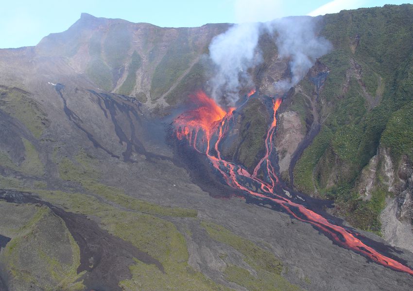
Panorama
            du champ magnétique terrestre
                                         Gauthier Hulot

               Equipe de Géomagnétisme
        Institut de Physique du Globe de Paris
     Université Paris Diderot, Sorbonne Paris Cité
                         CNRS

Panorama du champ magnétique terrestre      Institut d’Astrophysique Spatial, Orsay   18/01/2018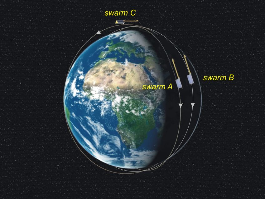
Le champ magnétique terrestre
n   Définition historique: ce qui oriente ma boussole, à relativement basse
    fréquence (pour que je puisse voir la boussole réagir)
n   Il s’agit donc du champ magnétique produit par toutes les sources
    terrestres dans la gamme de fréquence 0-1Hz (et un peu au-delà)

                                    Modifié de
                                    http://tubeaessai.blogs.nouvelobs.com/images/medium_Boussole.jpg

                                Matière aimantée

                                                                    Courants électriques                     www.britannica.com

        Panorama du champ magnétique terrestre                     Institut d’Astrophysique Spatial, Orsay   18/01/2018           2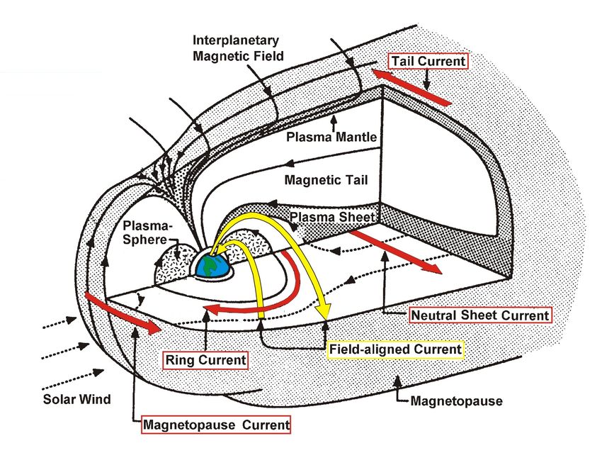
Une grande variété de sources
 n     La source principale est la géodynamo qui se trouve dans le noyau
 n     Son champ est responsable de l’aimantation des roches, source secondaire
 n     Mais il existe aussi des courants électriques dans l’ionosphère, la
       magnétosphère, et même dans les océans…

                                                           Les roches de la croûte
                                                           terrestre sont aimantées
                                                           par le champ du noyau

                                                   Dans l’ionosphère
                                                   ionisée par le Soleil
                                                   et animée de marées
                                                   thermiques, des
                                                   courants électriques
                                                   circulent

                                                                                Dans la magnétosphère, le mouvement
J. Aubert, IPGP
                                                                                des particules chargées forment des
                                                                                courants électriques de grande échelle
Dans le noyau liquide et conducteur,
siège une dynamo autoentretenue
                  Panorama du champ magnétique terrestre     Institut d’Astrophysique Spatial, Orsay   18/01/2018   3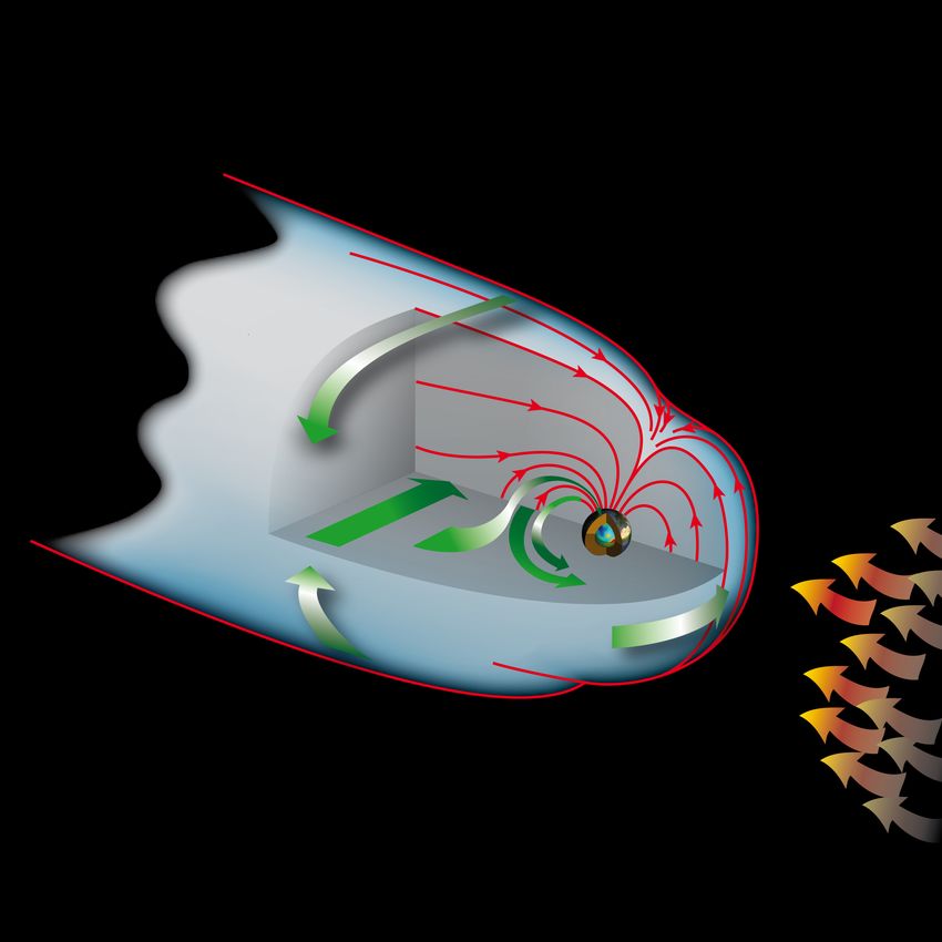
Comment observe-t-on le champ magnétique ?

                           Observatoires ayant fourni des données entre 1997 et 2012 (points rouges) et trace d’une
                           journée d’orbite du satellite Oersted (Hulot et al., TOG, 2015)

n   Dans des observatoires : ils voient très bien les variations temporelles, mais la couverture
    géographique est mauvaise
n   Grâce à des levés, qui permettent de cartographier le signal des sources proches sur
    des petites surfaces, avec des résolutions inégales, et qui forment un « patchwork » sans
    cohérence aux échelles intermédiaires
n   Grace à des satellites en orbite basse, qui offrent une couverture géographique globale
    dense, mais qui bougent très vite (une orbite en 90 minutes !)

          Panorama du champ magnétique terrestre          Institut d’Astrophysique Spatial, Orsay           18/01/2018   4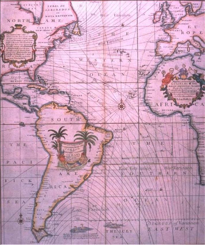
Qu’observe-t-on
                1 Observations dans un observatoire ?

iation diurne géomagnétique

                                                                                       Electrojet        Courants alignés
                                                                                       auroral

                                                               Electrojet          courants
                                                               equatorial          diurnes

                               Midi
                                         (A. Chulliat, IPGP)
r 2014              M1/M2 Magnétisme Terrestre 1                            3                                  (ESA)

              CLF, 23 Septembre 2009

         Variations diurnes liées à l’heure locale par temps magnétiquement calme,
                        signal ionosphérique et courants induits (~ 20 nT)
                Panorama du champ magnétique terrestre         Institut d’Astrophysique Spatial, Orsay        18/01/2018    5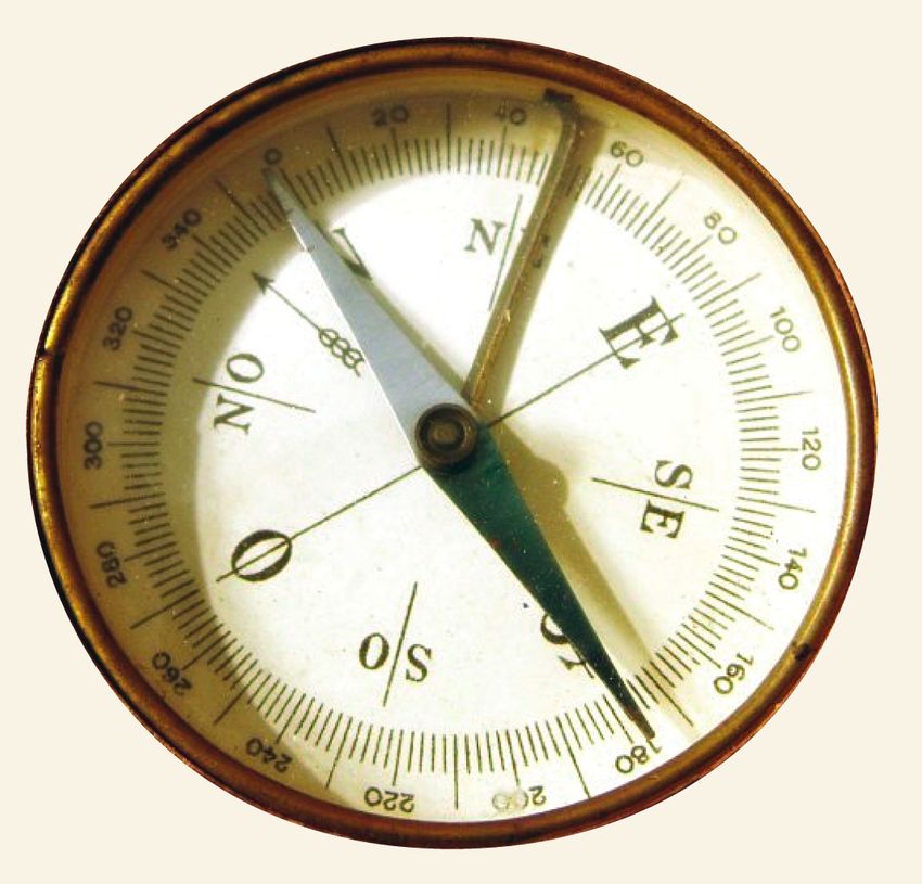
Qu’observe-t-on dans un observatoire ?

                                              (A. Chulliat, IPGP)

                                                                                         (G. Hulot, J. Dyon, IPGP)

        CLF, 20 et 21 Novembre 2003

Variations rapides liées au temps universel lors d’un orage magnétique
      Signal magnétosphérique et courants induits (qqes 100 nT)
     Panorama du champ magnétique terrestre    Institut d’Astrophysique Spatial, Orsay        18/01/2018             6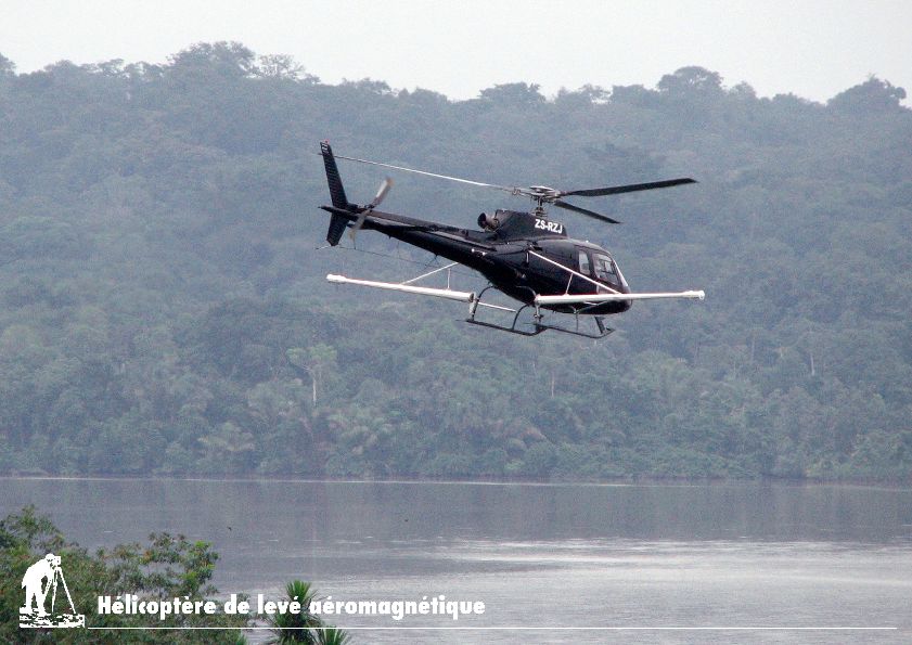
Qu’observe-t-on dans un observatoire ?

                                                                 J. Aubert, IPGP

Variations dues à l’évolution du champ de la
     géodynamo (~ 40 000 nT, ~ 20 nT/an)
                                                                                   Alexandrescu et al., PEPI, 1996

     Panorama du champ magnétique terrestre   Institut d’Astrophysique Spatial, Orsay               18/01/2018       7
Qu’observe-t-on à bord des satellites ?

                                                                                              N. Olsen,
                                                                                              DTU Space,
                                                                                              Copenhagen, DK

Vision spatio-temporelle du champ magnétique à l’altitude des satellites en orbite basse

         Panorama du champ magnétique terrestre   Institut d’Astrophysique Spatial, Orsay   18/01/2018    8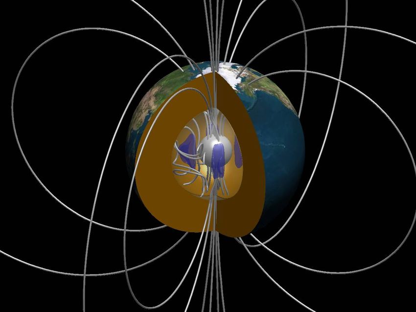
Les défis du magnétisme spatial
n   Observer des signaux qui se superposent, dont le plus intense (le champ
    du noyau, 20.000 à 60.000 nT) varie lentement (qqes 10nT/an) et masque des
    signaux bien moins intenses (par exemple le champ des roches aimantées,
    de l’ordre de 10nT, avec des détails de petite échelle nécessitant de mettre en
    évidence des signaux < 0.1 nT).
n   Ceci nécessite une mesure absolue très précise (typiquement < 0.2 nT en
    justesse et résolution)
n   Par ailleurs, il faut être en mesure d’exploiter les propriétés spatio-
    temporelles et physiques des différents signaux pour les identifier
    séparément, par exemple:
          signaux héliosynchrones (ionosphériques) versus
          signaux fixes en coordonnées géographiques (roches aimantées)
          signaux externes (liées à des sources au-dessus des satellites) versus
          signaux internes (liés aux sources sous le satellite)
n   Ceci nécessite une mesure vectorielle orientée dans l’espace
    (typiquement < 5 arcsec en justesse et résolution)

        Panorama du champ magnétique terrestre   Institut d’Astrophysique Spatial, Orsay   18/01/2018   9
Des défis qui n’ont pu être relevés qu’à partir des années 1980
                                 n       MAGSAT, 1980 (USA) Altitude de 325-550 km, avec une
                                         inclinaison de 97°, en héliosynchrone (6h00-18h00),
                                         mais n’est resté en orbite que six mois.

   MAGSAT

  n   Oersted, 1999 (Danemark, avec un magnétomètre
      français) Altitude de 650-850 km, avec une
      inclinaison de 97°, mais n’est plus héliosynchrone, a
      fourni plus de 10 ans de données.                                      Oersted

   CHAMP                             n    CHAMP, 2000-2010 (Allemagne, avec un magnétomètre français)
                                          Altitude de 450 km (250 km en fin de mission), inclinaison de
                                          87°, non- héliosynchrone, a fourni 10 ans de données.

  n   SWARM, lancée en Novembre 2013 (ESA/CNES), deux
      satellites côte-à-côte (inclinaison 87.4°, 460 km), un
      troisième satellite sur une orbite plus haute se séparant en
      heure locale (inclinaison 88°, 520 km)

            Panorama du champ magnétique terrestre    Institut d’Astrophysique Spatial, Orsay   18/01/2018   10
La puissance des mathématiques au service de
l’identification des sources du champ et de
l’exploitation des observations
n Le champ magnétique obéit aux équations de Maxwell :
$ ∂E '
∇. B = 0 ∇ × B = µ0 & j + ε0 )
% ∂t (
n Dans un volume sans source (notamment, l’atmosphère terrestre), et en négligeant la
propagation des ondes électromagnétiques (nous observons les variations du champ à
des fréquences très basses), ces équations se simplifient en:
∇. B = 0 ∇×B = 0
n Ce qui permet d’affirmer que le champ magnétique dérive d’un potentiel harmonique :
B = −∇V ΔV = 0
n Un théorème dû à C.F. Gauss permet alors d’affirmer que si on peut mesurer le vecteur
champ magnétique partout sur une surface sphérique séparant les sources internes
des sources externes (par exemple la surface de la Terre), alors on peut déterminer à
la fois le potentiel dû aux sources internes, et celui dû aux sources externes.
n En outre, on peut alors en déduire la valeur du champ magnétique en tout point dans
le volume libre de toute source.
Panorama du champ magnétique terrestre Institut d’Astrophysique Spatial, Orsay 18/01/2018 11La puissance des mathématiques au service de
l’identification des sources du champ et de
l’exploitation des observations
J. Aubert, IPGP
n C’est ainsi que l’on constate que le champ variant lentement (qui domine) est en très
grande majorité d’origine interne, alors que le champ variant vite est en très grande
majorité d’origine externe.
n En outre, il est alors possible d’étudier chacun des champs séparément, et de
« remonter » les lignes de champs jusqu’aux sources
Panorama du champ magnétique terrestre Institut d’Astrophysique Spatial, Orsay 18/01/2018 12Reconstruction des courants électriques diurnes circulant dans
l’ionosphère
30
à partir des données de Swarm et des observatoires
A. Chulliat et al.
01 Janvier (Hiver Nordique)
Chulliat et al., EPS, 2016
Fig. 7 (Normalized) equivalent current function , DIFI-2015b model, for January 1,
Ces courants
n UT=12 and F10.7 = sont essentiellement
100 SFU. is normalized by fixes face au
the maximum Soleil,
value for all mais
seasons.sontsensibles
Aà13.1
la kA
structure locale
current flows duthechamp
between contours. principal, aux saisons et à l’activité du Soleil.
Panorama du champ magnétique terrestre Institut d’Astrophysique Spatial, Orsay 18/01/2018 13Reconstruction des courants
Fig. 7 (Normalized) equivalent current function électriques
, DIFI-2015b model,diurnes
for January 1,circulant dans
l’ionosphère
UT=12 and F
à= partir
10.7 100 SFU.
des données de Swarm et des observatoires
is normalized by the maximum value for all seasons.
A 13.1 kA current flows between the contours.
01 Avril (Printemps Nordique)
Chulliat et al., EPS, 2016
Fig. 8 (Normalized) equivalent current function , DIFI-2015b model, for April 1, UT=12
Ces
n and courants
F10.7 = 100 SFU.sont essentiellement
is normalized fixesvalue
by the maximum facefor au Soleil,A mais
all seasons. 13.1 kAsont
sensibles
à la structure
current flows between locale du champ principal, aux saisons et à l’activité du Soleil.
the contours.
Panorama du champ magnétique terrestre Institut d’Astrophysique Spatial, Orsay 18/01/2018 14Reconstruction des courants électriques diurnes circulant dans
l’ionosphère à partir des données de Swarm et des
Swarm Dedicated Ionospheric Field Inversion 31
observatoires
01 Juillet (Été Nordique)
Chulliat et al., EPS, 2016
Fig. 9 (Normalized) equivalent current function , DIFI-2015b model, for July 1, UT=12
Ces
n and F10.7courants
= 100 SFU.sont essentiellement
is normalized fixesvalue
by the maximum facefor au Soleil,A mais
all seasons. 13.1 kAsont
sensibles
à la flows
current structure
between locale du champ principal, aux saisons et à l’activité du Soleil.
the contours.
Panorama du champ magnétique terrestre Institut d’Astrophysique Spatial, Orsay 18/01/2018 15Reconstruction des current
Fig. 9 (Normalized) equivalent courants
function ,électriques
DIFI-2015b model, fordiurnes
July 1, UT=12circulant dans
l’ionosphère
and F10.7
à partir
= 100 SFU.
des données de Swarm et des observatoires
is normalized by the maximum value for all seasons. A 13.1 kA
current flows between the contours.
01 Octobre (Automne Nordique)
Chulliat et al., EPS, 2016
Fig. 10 (Normalized) equivalent current function , DIFI-2015b model, for October 1,
Ces and
n UT=12 courants sont
F10.7 = 100 essentiellement
SFU. fixes
is normalized by the facevalue
maximum au Soleil, maisAsont
for all seasons. sensibles
à la
13.1 kA structure
current flows locale ducontours.
between the champ principal, aux saisons et à l’activité du Soleil.
Panorama du champ magnétique terrestre Institut d’Astrophysique Spatial, Orsay 18/01/2018 16Le théorème de Gauss ne permet pas de séparer le
signal de l’aimantation des roches de celui dû à la
géodynamo, peut-on contourner cette difficulté ?
J. Aubert, IPGP
n Ces champs magnétiques sont en effet tous deux d’origine interne...
n Mais on peut tirer parti des informations géophysiques et physiques dont on
dispose par ailleurs.
n On sait en particulier qu’une roche ne peut pas conserver d’aimantation si sa
température dépasse la « température de Curie » (typiquement 600°C). Cette
température est rapidement atteinte lorsque l’on s’enfonce dans la Terre (en moins
de 100km, parfois beaucoup plus vite, par exemple près des dorsales océaniques).
Panorama du champ magnétique terrestre Institut d’Astrophysique Spatial, Orsay 18/01/2018 17Figure 1 implieslimitationson termsof highdegree/order,
yet lessthan fourteen. For exampleone shouldnot expect
Analyse du spectre spatial du champ d’origine interne
to determine terms of degree/ordertwelve and thirteen to
within 1% since more than 1% of the contribution at these
wavelengthsis crustalin origin.
1o1ø • i i i i i [ i i i [ i i i • • i I i I i i i i i i i lOlS L’analyse de Gauss permet aussi de
n
n •
décomposer le potentiel du champ en
Rn= (n+ 1)m•=O[(gnm) a+ (hnm) a]
10s- • 10•"
fonctions élémentaires, les Harmoniques
2 REPRESENTING THE FIELD
Sphériques, caractérisées par un degré n,
l lo TM
définissant l’échelle spatiale considérée: plus n
10" (• t est grand, plus l’échelle est petite.
n Le « spectre spatial » permet de représenter (ici
3:
lO'URFACE
OF
EARTH
•) 10•-
ttß - en échelle logarithmique) la contribution de
chaque échelle spatiale (chaque degré n) à
l’intensité moyenne observée.
n
10'ø ,(
A la surface de la Terre, on observe que le
dipôle (n=1) est dominant, puis que le spectre
ß CORE-MANTLE •
ß
décroit rapidement jusque vers le degré 13,
& •U•A•
••
10' •
10 • -
où il devient plat…
9+
.
pg (cos €3) cos
Un spectre plat est la signature attendue de
9
n
Figure 2. Map of zero lines and tesserae in which the sign of the spherical
harmonic is constant for a zonal harmonic ( P z ) a sectorial harmonic (P: cos 9@)
sources proches.
and a tesseral harmonic (P;, cos 9@). (Courtesy of D. Barraclough.)
3)
7)
)
10
•- C•Rn
10 • -=1'34'
x10'
(0'270)n
(nT)z where
normal
we have
3 are arbitrary scalar functions and S is a closed surface with
@,
bounding Q, and setting
ds
Then, since V2v 0,
(VV2V+ W . W ) d Q =
n A la surface de la Terre, il s’agit des roches
V, the magnetic potential,
=@ =
aimantées.
(40)
En « prolongeant » le champ jusqu’à la
=
7) n
2) 10 - Langel and Estes, ST: Rn = 37.1 (0.g74) n (nT) z
surface du noyau, c’est la première partie du
9) GRL, 1982
9) spectre qui devient quasi-plate, confirmant
9) 0 • :• :• • • • '• •1• 110
1•11•
113
114
115
n
116
1•7116 1192•0 ;1;2213 ;42•5 216 ;7 qu’il s’agit d’un signal venant du noyau.
3)
5) :Fig.]. Geomagnetic
fieldspectum.
Rn is thetotalmean
0) squarecontributionto the vectorfield by all harmonicsof
degreen. ThePanorama dutochamp
curvesare fit magnétique
the surface terrestre
resultand extra- Institut d’Astrophysique Spatial, Orsay 18/01/2018 18
polated to the core-mantleboundary.De nombreuses données historiques sont aussi disponibles
n La boussole est connue des chinois depuis
deux millénaires, et arrive en Europe vers le
XIIième siècle.
n La déclinaison est connue à partir du VIIIième
siècle en Chine, milieu du XVième en Europe.
n L’inclinaison est découverte au milieu du
XVIième siècle
n La variabilité spatiale de la déclinaison, et
l’importance de la boussole pour la
navigation, suscite les premières campagnes
de mesure (à droite la carte de E. Halley,
1701)
n On ne prend conscience de la variation
séculaire en Europe qu’au cours du XVIIième,
ce qui motive la mise en place d’observatoires
royaux pour mesurer le champ régulièrement.
n On ne comprend comment mesurer l’intensité
du champ qu’au début du XIX.
n Les observatoires magnétiques se
généralisent alors dans le monde.
Courtillot et Le Mouël, 2007
Panorama du champ magnétique terrestre Institut d’Astrophysique Spatial, Orsay 18/01/2018 19Ces données historiques peuvent aussi nous renseigner sur
le comportement passé du champ
n Leur distribution est assez dispersée à la 964 1800-1849
A. Jackson, A. R. T. Jonkers and M. R. Walker
surface de la Terre -> il n’est possible de (g)
reconstruire que les grandes échelles du
champ interne (celles du champ du noyau,
pas celles du champ de l’aimantation).
n Les sources cumulées d’erreur ne permettent
pas de modéliser le champ externe.
n Ces données permettent donc surtout de
reconstruire le comportement passé du (h)
champ du noyau (les champs dus aux
sources aimantées et aux sources externes
étant traités comme du bruit).
n Pour les époques antérieures à 1840,
cependant, seules des données de
direction du champ sont disponibles
(Déclinaison et Inclinaison). Aucune Figure 1. (Cont.) (g) All data 1800{1849. (h) All data 1850{1899.
observation de l’intensité du champ n’existe. 1850-1899
shortcoming of the compilation is the fact that data were omitted by Sabine when
Mais on peut quand même exploiter ces forming his compilation from the original sources. Since the world compilations are
Jackson
by region rather than by voyage and areet al.for(2000)
only the zones 40{85 N, 0{40 N and
informations ! 0{40 S, data from greater than 40 S have been omitted (notwithstanding the data
originating in the Magnetic Survey of the South Polar Regions undertaken between
1840 and 1845, reported in Sabine (1868)). We used Sabine’s dataset as the basis
for creating a new dataset in which individual voyages are represented, and we used
the original sources to reinstate missing data from the voyages. A more complete
account will be forthcoming.
Panorama du champ magnétique terrestre Institut d’Astrophysique
A major sourceSpatial,
of data for Orsay 18/01/2018
the early 19th century 20
originates as two manuscript
compilations held in the Archives Nationales and the Bibliotheque Nationale in Paris.Un autre résultat mathématique fort utile
J. Aubert, IPGP
n A condition de faire l’hypothèse que toutes les sources sont internes à la Terre (de toute
façon, on est contraint de traiter les sources externes comme source de bruit), il est
possible de reconstruire la « forme » des lignes de champ, et donc le champ à un facteur
global près, car le champ à la surface de la Terre ne possède que deux pôles (Hulot et al.,
GJI, 1997).
Panorama du champ magnétique terrestre Institut d’Astrophysique Spatial, Orsay 18/01/2018 21On peut ainsi cartographier le champ principal…
-70000 0 70000
Modèle CHAOS-4α,
[nT]
Cf. Hulot et al., TOG, 2015
Composante radiale du champ magnétique principal en 2010,
à la surface de la Terre
Panorama du champ magnétique terrestre Institut d’Astrophysique Spatial, Orsay 18/01/2018 22…« remonter » les lignes de champ jusqu’au noyau,
-1000 0 1000
[µT]
Modèle CHAOS-4α,
Cf. Hulot et al., TOG, 2015
Composante radiale du champ magnétique principal en 2010,
à la surface du noyau
Panorama du champ magnétique terrestre Institut d’Astrophysique Spatial, Orsay 18/01/2018 23et étudier la dynamique de la géodynamo
à la surface du noyau.
Jackson et al,
Phil Trans R. Soc, 2000
Reconstruit grâce aux données historiques depuis 1590, et aux missions POGO (1965-1970) et
MAGSAT (1979-1980), unités en nT. L’intensité globale avant 1840 est basée sur une simple
extrapolation vers le passé de la composante dipolaire.
Panorama du champ magnétique terrestre Institut d’Astrophysique Spatial, Orsay 18/01/2018 24et étudier la dynamique de la géodynamo
à la surface du noyau.
Gillet et al, GGG, 2013
Reconstruit grâce aux données historiques depuis 1840, et aux missions POGO (1965-1970),
MAGSAT (1979-1980), DE-2, Oersted (depuis 1999) et Champ (2000-2010), unités en mT
Panorama du champ magnétique terrestre Institut d’Astrophysique Spatial, Orsay 18/01/2018 25C’est la dynamique de la géodynamo qui est à l’origine de la 1226 C. C. Finlay et al.
croissance de l’anomalie d’intensité de l’Atlantique Sud
IGRF 1945 IGRF 1980 IGRF 2005
1226 C. C. Finlay et al.
Finlay et al,
GJI, 2010
Cette anomalie s’intensifie et s’étend.
Figure 3. Evolution of the South Atlantic Anomaly during the 20th century: Top plot (a) shows how the minimum F at the Earth’s surface (in the South
Atlantic Anomaly where the magnitude of the field is smallest) has decreased from 1900 towards the present day, units are nT. The bottom plot (b) tracks
the location of the point of lowest field magnitude with time; the colour scale indicates the magnitude of F, with blue representing smallest magnitude, units
are nT.
Fortran software for synthesizing the field from the coefficients: C software for synthesizing the field from the coefficients
Panorama du champ magnétique terrestre Institut d’Astrophysique Spatial,
http://www.ngdc.noaa.gov/IAGA/vmod/igrf11.f Orsay
(Windows): 18/01/2018 26
http://www.ngdc.noaa.gov/IAGA/vmod/geomag70_windows.zip
C software for synthesizing the field from the coefficientsOn peut également remonter à la cause du
B07101 CHULLIAT ET AL.: NORTH MAGNETIC POLE ACCELERATED DRIFT B07101
B07101 déplacement rapide récent du pôle magnétique Nord
CHULLIAT ET AL.: NORTH MAGNETIC POLE ACCELERATED DRIFT B07101
Figure 2. Average drift speeds (in km/yr) from the observed NMP positions (in blue), represented as
stairs delimited by the observation dates, and with estimated error bars. Drift speed (in km/yr) of the
NMP positions calculated from the gufm1 (in green), CM4 (in red) and CHAOS‐2 (in light blue) geomag-
netic models.
1989 2002
small (less than 200 km) and one should keep in mind that Mandea [2007a]) actually found 1969 and 1978 extrema
19th century data used in gufm1 are probably not as good as in their gufm1 curve, a result we were not able to reproduce.
20th century data, due to the very limited number of reliable Average drift speeds obtained from surveys seem to be in
magnetic observatories before 1900 [Jackson et al., 2000]. better agreement with the CM4 model than with gufm1
[11] 2. From 1904 to 1984, the observed NMP positions between 1983 and 1994, but do not discriminate between
show an almost linear increase in distance with time, at a these models for earlier time intervals (1962–1973 and
speed of around 10 km/yr. There are small oscillations in the 1973–1984). The most prominent feature in Figure 2 is the
model curves that cannot be confirmed by direct observa- dramatic increase in drift speed that took place in the 1990s,
tions since the time intervals between successive observa- from 15 km/yr to a little more than 50 km/yr according to
tions are too large. surveyed positions, and even 60 km/yr according to the
[12] 3. From 1984 to 2001, both direct observation and the CM4 and CHAOS‐2 models. This acceleration is well above
CM4 model show a large increase in drift rate, from about the error bars on average drift speeds obtained from the
10 km/yr to 50 km/yr. observed positions. The CM4 and CHAOS‐2 models make
[13] 4. From 2001 to the present, the drift velocity has it possible to determine that the period of acceleration began
remained high (about 50 km/yr) but the acceleration has in 1989 and ended in 2002. It is worth noting that CM4 is
been close to zero. based on satellite data providing a good spatial coverage
Chulliat et al, JGR, 2010
[14] The same four phases are visible in Figure 2, which before (MAGSAT) and after (Ørsted and CHAMP) the
shows the NMP drift speed versus time. In Figure 2, the 1990s. Furthermore, the fact that the pole acceleration is
average drift speeds from the observed NMP positions are reproduced by the internal spherical harmonic
of thecoefficients
Accélération due à la dynamique d’une tâche de flux inverse dans le cylindre tangent
Figure
surface
7. Polar
from the
views (from
CM4 model
colatitude
in (a) 1989
0° to 55°)
and (b) 2002.
order not to confuse them with instantaneous drift speeds acceleration is followed by a leveling off of the drift
radial secular variation (in mT/yr) at the core
represented as stairs delimited by the observation dates in clearly points at a core origin of this phenomenon. The steep
(c and
speedd) Same for the radial magnetic field
(in mT) at the core surface;
obtained from time varying spherical harmonics models. of the observed NMP the B = 0 level curves are represented
r positions, and even a slight decrease as dashed black curves. The NMP
(at the Earth’s
Assuming that the positional error for all observed positions surface) is represented
in the drift speed of NMP by positions
a red dot. The location
determined of the maximum change in total secular
from the
is 40 km (see above), we calculated errorvariation
bars on average CHAOS‐2 model
(radial component) aftercore
at the 2002.5.
surface over the time interval 1989 to 2002 is represented by a
drift speeds
pffiffiby
ffi dividing the error in the black
distance between
star. The black solid circle represents the trace at the core surface of the cylinder tangent to the inner
points (40 2 = 56 km) by Panorama
the number of du yearschamp
core.
between magnétique terrestre
3. NMP Drift Speed and Secular Variation Institut d’Astrophysique Spatial, Orsay 18/01/2018 27
observations. The increase of these error bars in recent years
in the North Polar RegionC’est cette dynamique qui est à l’origine de l’accélération soudaine du déplacement du pôle magnétique Nord. Expeditions • 1831 James Clark Ross • 1904 Roald Amundsen • 1948-2007 Précédents satellites • Ørsted • CHAMP Swarm
riding on top, the processed data of the resid-cies f (where f ! 1/T and T is the period in magnetic field, high-
pass filtered with a cut-
ual field reveal a dynamic field morphologyyears) of the zonal motion of the residual off period of 400 years
field at each latitude. At the equator, the
On peut également mettre en évidence la présence d’ondes
that evolves rapidly over the 400 years stud-
ied (Fig. 1) (movie S3). In the equatorialdominant wavenumber was m ! 5 (i.e., " !
region we observe a series of high-amplitude72°) and f ! 3.75 # 10 year (i.e., T !
$3 $1
(referred to in the text
as the residual field),
shown at the core sur-
se propageant à la surface du noyau
flux foci moving westward. Field changes are270 years), whereas at 40°S, the field change
most obvious under the Atlantic hemispherewas less monochromatic with more power at
face in 1850.
while less activity occurs under the Pacificlower wavenumbers. At 20°N, we found a
hemisphere, suggesting some longitudinalstrong m ! 8 signal consistent with high-
modulation of the field or of the mechanismresolution maps of the radial magnetic field at
causing its motion (12, 13). the core surface, recently obtained from sat-
We constructed time-longitude diagramsellite measurements (17).
REPORTS Fig. 2. Time-longitude diagrams of the residual field at specific latitudes (A)
The gradient of a diagonal line produced by (B) 40°S. Frequency-wavenumber spectra of these time-longitude diagrams
ut cap- (14 –16)
Observations of zonal of theof residual
motion mag- field
both every 2° could
of which of conceivably be occur- (D), respectively; peaks pinpoint the dominant zonal wavenumbers (m) and
he core latitude
netic field at low latitudes caninbeorder to viewring
accounted zonal motions,
at the a moving
surface feature core.
of Earth’s in a time-longitude
One diagram where T is the period) of the zonal field motions.
ble to which are mechanisms,
for by two rather different important in rapidly rotating is
possibility fluidsmeasures the apparent
that a westward equatorial jet zonal speed of that fea-
on that such as Earth’s liquid outer core because ofture. We determined the power traveling at all
F
a stat- the influence of strong Coriolis forces. West-possible Fig. gradients
1. Snapshot in our time-longitude dia-
of the w
eatures ward motion of a succession of flux foci was grams by means of
nonaxisymmetric radial a technique based on the
s
resid- observed at the equator (Fig. 2A) and lessRadon transformfield,
magnetic (18, 19). A prominent peak at
high- a
hology clearly at mid-latitudes (e.g., Fig. 2B atthe equator (Fig. 3) identifies the highest am-
pass filtered with a cut- t
40°S). Two-dimensional frequency-wave-plitude, off most
period of 400
robust years
zonal motion of the resid- o
s stud- (referred
atorial number power spectra were calculated fromual field in thetorecord,
in the attexta speed of 17 km e
as the residual $1 field), 7
the time-longitude diagrams. Peaks in theseyear shown (0.27° yearcore ) westward. Less pro-
$1
plitude at the sur- m
ges are spectra pinpoint the preferred zonal wave- nounced peaks
face in 1850. were found at latitudes 55°N (18
e
numbers m (where m ! 360°/" and " is thekm year or 0.49° year ) and at 40°S (26 km
$1 $1
sphere b
angular wavelength in degrees) and frequen-year or 0.56° year ). To assess the longev-
$1 $1
Pacific w
udinal cies f (where f ! 1/T and T is the period inity of the peaks, we applied the Radon speed –
years) of the zonal motion of the residualdetermination method to time subwindows of r
hanism a
field at each latitude. At the equator, the the time-longitude diagrams. We found that the
i
agrams dominant wavenumber was m ! 5 (i.e., " !striking equatorial peak was present through- 4
2° of 72°) and f ! 3.75 # 10 year (i.e., T !
$3 $1 out, whereas the smaller peak at 55°N was a
otions, 270 years), whereas at 40°S, the field changeobvious only from 1750 to 1880 and the peak y
fluids was less monochromatic with more power atat 40°S was strongest from 1800 to the present.
use of lower wavenumbers. At 20°N, we found a
West- strong m ! 8 signal consistent with high- www.sciencemag.org SCIENCE VOL 300 27 JUNE 2003
ci was resolution maps of the radial magnetic field at
d less the core surface, recently obtained from sat-
2B at ellite measurements (17). Fig. 2. Time-longitude diagrams of the residual field at specific latitudes (A) 0° (the equator) and
The gradient of a diagonal line produced by (B) 40°S. Frequency-wavenumber spectra of these time-longitude diagrams are shown in (C) and
-wave- (D), respectively; peaks pinpoint the dominant zonal wavenumbers (m) and frequencies ( f ! 1/T,
d from a moving feature in a time-longitude diagram
these Ondes d’ordre 5, de période 300 ans, se propageant le long de l’équateur à environ 20km/an
measures the apparent zonal speed of that fea-
where T is the period) of the zonal field motions.
wave-
is the
dans l’hémisphère atlantique
ture. We determined the power traveling at all
possible gradients in our time-longitude dia- Fig. 3. Power moving
with eastward zonal
equen-
riod in
(Finlay and Jackson, Science, 2003)
grams by means of a technique based on the
Radon transform (18, 19). A prominent peak at
speeds between –60
and 60 km year$1 in
esidual the equator (Fig. 3) identifies the highest am- time-longitude diagrams
or, the plitude, most robust zonal motion of the resid- of the residual field, ev-
., " ! ual field in the record, at a speed of 17 km ery 2° latitude from
., T ! year$1 (0.27° year$1) westward. Less pro- 70°N to 70°S. A maxi-
nounced peaks were found at latitudes 55°N (18 mum is found at the
change Panorama du champ magnétique terrestre Institut d’Astrophysique Spatial, Orsay equator, indicating 18/01/2018
a ro- 29
wer at km year$1 or 0.49° year$1) and at 40°S (26 km bust measurement of
$1 $1On peut également mettre en évidence la présence d’ondes
se propageant à la surface du noyau
NATURE | Vol 465 | 6 May 2010 LETTERS
a 1 a
0.2 LUNAR97
0.8 data
Ensemble
Filtered LOD change (ms)
0.1
Coherence
0.6
0.4
0
0.2
–0.1
0
b 180 –0.2
Assimilation
120
b 1
Phase (degree)
60
0
0.8
Cylindrical radius
−60
−120 0.6
−180
30 20 15 10 8 7 6 5 4 3 0.4
Period (years)
Figure 1 | High coherence is found not only on long timescales, but also on 0.2
an approximately six-year period. Coherence (a) and phase (b) spectra are
calculated over the time span 1925–1990 for the DLOD time series
LUNAR97 (ref. 13) and the predictions from the average of an ensemble of 0
1955 1960 1965 1970 1975 1980 1985
quasi-geostrophic core flow models (see Supplementary Information).
Figure 4: Schematic diagram of the structure of torsional oscillations.
Time (years) The vertical axis
Green segments correspond to frequency ranges over which the phase shift is
smaller than 30u. Figure 2 | The six-year DLOD signal is carried by geostrophic wave-like
Ondes de type oscillations
coincides with the deEarth’s
torsion,rotationde période axis, 6and ans environ,
core
patterns
flow moves mettant
travelling from
on l’ensemble
the inner core
uniform du noyau
cylinders.
to the outer core Equator.
Theen
a, Comparison of DLOD time series, bandpass-filtered between five and
mouvement, et from
responsables de variations infimes danseight
the tangent cylinder to the Equator. Such fast propagation is
made possible by a large magnetic field inside the core, of amplitude
layears,
rotation de data
of the LUNAR97 la Terre (amplitude
(green), the predictions from thede 0.2 ms)
13
expression in the surface flow in the northern and
ensemble southern
average hemispheres
of the quasi-geostrophic should
core flow models (black), andbe
the the
(Gillet et al., Nature,
several millitesla. At large cylindrical radii, in the Equatorial region,
the propagation slows down. In a torsional wave scenario, that obser-
$ 2010)
result (red)
~t ðt Þ
% of the torsional wave assimilation of the flow coefficients
obs
for 1960–1982 (see Supplementary Information). b, Time
n0
same.
vation Figure
is consistentcourtesy
with a weakerof field
Dr.closeStephen Zatman.
to the Equator.
n~1,3,...,9
versus cylindrical radius map of the band-pass filtered angular velocity
Furthermore, the absence of a reflected wave suggests the presence ũg(s, t) for the ensemble average of the quasi-geostrophic core flow model.
of significant Ohmic dissipation. This is due either to large gradients Distance is in outer core radius units. The colour scale ranges between
of the induced magnetic field, resulting from inhomogeneities in the 20.4 km yr21 (blue) and 10.4 km yr21 (yellow) with contours every
0.02 km yr21. The horizontal dashed line at s 5 0.35 corresponds to the
Panorama du champ
Alfvén wave velocity, ormagnétique terrestre
to the presence of a conducting layerInstitut
at the d’Astrophysique Spatial,
position of the tangent cylinder. Orsay
The black box corresponds18/01/2018
to the space- 30
base of the lower mantle19. We have explored this second hypothesis. time domain used for the assimilation of torsional waves (Fig. 3).On peut enfin tenter de comprendre l’origine des « secousses
magnétiques » découvertes à la fin des années 1970
Composante Est de la variation séculaire à Niemegk, Allemagne
Mandea et al., SSR, 2010
Ces secousses ne peuvent être expliquées par de simples ondes de torsion
(Silva and Hulot, PEPI, 2012)
Panorama du champ magnétique terrestre Institut d’Astrophysique Spatial, Orsay 18/01/2018 31On peut enfin tenter de comprendre l’origine des « secousses
10.1002/2015GL064067
magnétiques » découvertes à la fin des années 1970
Composante radiale de la dérivée seconde du champ
à la surface du noyau (Chulliat et al., GRL, 2015)
Les secousses les plus récentes (documentées par les données satellitaires) suggèrent qu’il s’agit de
pulsations (ondes stationnaires) du champ magnétique (Chulliat et al., GRL, 2010, 2015)
Figure 1. Maps of the radial secular acceleration at the core-mantle boundary, (left column) CHAMP + DMSP
(right column) CHAOS-5 model. The maps are shown at three different epochs (2003, 2009, and 2012.5), wh
Panorama du champ magnétique terrestre Institut d’Astrophysique Spatial, Orsay 18/01/2018 32
SA patches in the Atlantic sector are of maximum amplitude. The color scale does not take into account DML’étude des roches (et objets anciens) aimantés permet aussi
l’étude du champ magnétique ancien et très ancien
n L’aimantation des roches magmatiques donne des
informations sur l’intensité et l’orientation du champ
magnétique qui régnait localement lors du dernier passage
de ces roches sous la température de Curie, que l’on peut
dater grâce aux méthodes isotopiques (basées sur la
désintégration des éléments radioactifs à vie longue, comme
l’Uranium 238U)
n L’aimantation d’objets cuits (briques, poterie, tuiles…) donne
le même type d’information pour les époques historiques
anciennes (datées de manière diverses: archives historiques,
datation isotopique, etc…)
n L’aimantation (beaucoup plus faible, mais mesurable en
laboratoire) des roches sédimentaires donne aussi des
informations sur l’intensité (relative) et l’orientation du
champ magnétique lors de la formation de ces sédiments par
déposition, laquelle peut aussi être datée par des méthodes
isotopiques.
Panorama du champ magnétique terrestre Institut d’Astrophysique Spatial, Orsay 18/01/2018 33Evolution du champ magnétique à la surface du noyau sur
plusieurs millénaires
Genevey et al., 2008
Licht et al., PEPI, 2013
Ceci permet de constater que la dynamique qui a mené à la croissance de
l’anomalie de l’atlantique sud a vraisemblablement débuté vers 1500, et que d’autres
épisodes semblables se sont produits par le passé
Panorama du champ magnétique terrestre Institut d’Astrophysique Spatial, Orsay 18/01/2018 34the fluid core below.
Evolution du moment dipolaire du champ magnétique aux The popular story
The general impression is that nice, even bands of alternating polarized rock form as new
seafloor is made by the slow, steady movement of plates over millions of years and regular
échelles géologiques
reversals of the geomagnetic field about every 200,000 years. It is often illustrated with this
kind of diagram, which I call 'piano keys':
are quite ubiquitous over the deep afflictties cept for the cent
ocean basins; that they are interrupted (12) maintained,
only by anomalies associated with iso- At the time this concept was pro- are no linear ano
lated seamounts or volcanic ridges, posed there was very little concrete central anomaly
20 and by fracture zones which offset the evidence to support it, and in some ridges.
anomaly pattern-,-as was shown by ways it posed more problems than it 3) The idea di
Vacquier in the northeast Pacific (12). solved. There were, for example, at explain the fact t
Moment dipolaire virtuel (1022A.m2)
15 Of the three basic assumptions of least three rather awkward points that short-wavelength
the Vine and Matthews hypothesis, it did not explain: on either side o
field reversals (7) and the importance 1.) Many workers felt and feel that give way to h
10 of remanence (13) have recently be- the northeast Pacific anomalies do not wavelength anom
come more firmly established and wide- parallel any existing or preexisting distant flanks-an
ly held; thus in demonstrating the ef- oceanic ridge (14). ly made by Vin
5 ficacy of the idea one might provide 2) Whereas one can visually corre- and emphasized
virtual proof of the third assumption: late anomalies on widely spaced pro- Pichon (15). With
0 ocean-floor spreading, and its various files in the northeastern Pacific, one of the magnetic
implications. cannot do this over ridge crests, ex- from the ridge c
would expect dis
-5 135? 130' 125'
wavelengths but
amplitude.
CHARLOrrC
-10
Corollaries
-15 The second dif
fundamental, but
-20 J.P. Valet, IPGP #1~~~~~~~~~~~~~~~~~~~~~~~~~~~~~~~~~~~~~51
until recently no
of the crest of
thought to be a
0 0.5 1 1.5 2 2.5 3 3.5 4 1963 the U.S.
Age en millions d'années
500' Office (16) made
netic survey of R
west of Iceland (
was chosen beca
part of the north
2
Mid-Atlantic Rid
and because earl
cated a typical
its crest (18). A
the anomalies re
appears in Fig.
rized, approxima
square, shows a p
450 1______45
4 Ft alies paralleling
and symmetricall
This finding, tog
metry and linea
anomalies about
Gorda ridges (F
d’après Cande and Kent, 1995 scribed by Wilso
vincing confirma
obvious corollari
pretation of the
pothesis: (i) linea
should parallel
crests, and (ii) f
Tarling, 1971 L350 1300 125
orientations the
symmetric about
If one pursue
of the idea, a
Vine, Science, 1966
Fig. 1. Summary diagram of total magnetic-field anomalies southwest of Vancouver simulation of an
Island. Areas of positive anomaly are shown in black. Straight lines indicate faults
offsetting the anomaly pattern; arrows, the axes of the three short ridge lengths by assuming the
within this area-from north to south, Explorer, Juan de Fuca, and Gorda ridges. the last 4 millio
Cox, Doell, and
Ceci permet de constater que le champ magnétique est resté principalement dipolaire axial, mais qu’il
See also Fig. 15. [Based on fig. 1 of Raff and Mason (27); courtesy Geol. Soc. Amer.]
1406
s’est souvent inversé par le passé, à un rythme très variable, et que lors de ces inversions, le champ
a perdu temporairement son caractère dipolaire.
This content downloaded from 81.194.22.198 on Sun, 7 Dec 2014 12:56:46 PM
All use subject to JSTOR Terms and Conditions
Panorama du champ magnétique terrestre Institut d’Astrophysique Spatial, Orsay 18/01/2018 35Simulation numérique de la géodynamo dossier_67_aubert.xp 16/03/10 12:09 Page 29
LE NOYAU
n Le noyau possède encore une chaleur originelle (datant L’INTERFACE ENTRE LE NOYAU ET LE MANTEAU
TERRESTRE est thermiquement hétérogène,
de la formation de la Terre)
avec des parties chaudes (en rouge) et
froides (en bleu), visibles sur
cette simulation.
Ces hétérogénéités créent
des écoulements dans
le noyau (traits
n Son refroidissement est contrôlé par le manteau blancs) qui
influent sur la
géodynamo.
terrestre, lui-même en convection lente.
n Le taux de refroidissement est cependant suffisant pour
que le noyau soit en convection depuis la formation de
la Terre.
n Ce refroidissement a permis au noyau de cristalliser en
partie pour former la graine, qui continue de croître en
libérant de la chaleur et des éléments légers.
n La convection du noyau est donc thermo-solutale, et est assauts du vent solaire et des rayons cosmiques, Aubert et al., livres
violents courants électriques dans la magnétosphère
de sorte que la faune et la flore resteraient proté- (la zone dominée par le champ magnétique de la
contrôlée par des conditions aux limites complexes à sa Pour la science, 2010
• Collectif, Treatise
gées. La surface de la Terre serait tout de même planète) et l’ionosphère (une couche de la haute on Geophysics, vol. 5,
Geomagnetism, Elsevier, 2007.
plus exposée aux rayonnements, mais jusqu’à atmosphère, située entre 80 et 500 kilomètres d'al-
présent, aucun lien direct n’a été établi entre titude), en particulier lors des tempêtes solaires. articles
les inversions géomagnétiques et les disparitions Outre la multiplication des aurores boréales,
base (interactions avec la graine) et à son sommet
• J. ODENWALD et J. GREEN,
d’espèces. Nos lointains ancêtres ont d’ailleurs nous subirions, en l’absence de protections adap- En attendant la tempête solaire
connu plusieurs inversions ! tées, d’immenses pannes du réseau électrique. De du millénaire, in Pour la Science,
n° 374, décembre 2008.
Les principales précautions à prendre concer- telles pannes se sont d’ailleurs déjà produites à
• J. AUBERT et al.,
(interactions avec le manteau).
neraient le transport aérien et les satellites, qui ne quelques rares occasions, plongeant par exemple
Thermochemical flows couple
bénéficient pas ou peu de la protection de l’at- six millions de personnes dans le noir au Québec the Earth’s inner core growth to
mosphère, et qui subiraient alors directement l’agres- lors de la tempête solaire de 1989. Si le champ mantle heterogeneity, in Nature,
sion du vent solaire. Au sol, diverses protections magnétique protecteur avait en plus été affaibli par vol. 454, pp. 758-761, 2008.
seraient aussi à envisager. En effet, l’interaction du une inversion en cours, les conséquences auraient • J. AUBERT et al., The magnetic
Elle est par ailleurs influencée par la rotation de la Terre
structure of convection driven
vent solaire avec un champ magnétique terrestre probablement été bien pires ! Heureusement, ce
n
numerical dynamos, in Geophys. J.
réduit et multipolaire risquerait de déclencher de n’est pas à craindre à court terme… ■ Int., vol. 172, pp. 945-956, 2008.
(forces de Coriolis)
DOSSIER N° 67 / AVRIL-JUIN 2010 / © POUR LA SCIENCE
29
n Mais elle est suffisamment vigoureuse pour entretenir
une dynamo auto-entretenue: la géodynamo
Panorama du champ magnétique terrestre Institut d’Astrophysique Spatial, Orsay 18/01/2018 36Simulation numérique de la géodynamo dossier_67_aubert.xp 16/03/10 12:09 Page 29
La modélisation numérique de la géodynamo implique LE NOYAU
donc de résoudre numériquement: L’INTERFACE ENTRE LE NOYAU ET LE MANTEAU
TERRESTRE est thermiquement hétérogène,
avec des parties chaudes (en rouge) et
froides (en bleu), visibles sur
n Les équations d’une convection thermo-solutale en
cette simulation.
Ces hétérogénéités créent
des écoulements dans
le noyau (traits
blancs) qui
rotation rapide (température et composition, densité,
influent sur la
géodynamo.
mouvements)
n Couplées aux équations de l’électromagnétisme
(courants électriques, champ magnétique)
n En tenant compte de conditions aux limites thermiques,
ainsi que de conditions de flux de matière et
électromagnétiques.
Outre la distribution géographique des conditions aux
limites imposées par le manteau et la graine, et assauts du vent solaire et des rayons cosmiques,
de sorte que la faune et la flore resteraient proté-
Aubert et al., livres
violents courants électriques dans la magnétosphère
(la zone dominée par le champ magnétique de la
Pour la science, 2010
• Collectif, Treatise
gées. La surface de la Terre serait tout de même planète) et l’ionosphère (une couche de la haute on Geophysics, vol. 5,
l’existence de couplages gravitationnels entre la graine et
Geomagnetism, Elsevier, 2007.
plus exposée aux rayonnements, mais jusqu’à atmosphère, située entre 80 et 500 kilomètres d'al-
présent, aucun lien direct n’a été établi entre titude), en particulier lors des tempêtes solaires. articles
les inversions géomagnétiques et les disparitions Outre la multiplication des aurores boréales, • J. ODENWALD et J. GREEN,
d’espèces. Nos lointains ancêtres ont d’ailleurs nous subirions, en l’absence de protections adap-
le manteau, de nombreux nombres sans dimension
En attendant la tempête solaire
connu plusieurs inversions ! tées, d’immenses pannes du réseau électrique. De du millénaire, in Pour la Science,
n° 374, décembre 2008.
Les principales précautions à prendre concer- telles pannes se sont d’ailleurs déjà produites à
neraient le transport aérien et les satellites, qui ne quelques rares occasions, plongeant par exemple • J. AUBERT et al.,
Thermochemical flows couple
interviennent donc pour définir le bon « régime » de
bénéficient pas ou peu de la protection de l’at- six millions de personnes dans le noir au Québec the Earth’s inner core growth to
mosphère, et qui subiraient alors directement l’agres- lors de la tempête solaire de 1989. Si le champ mantle heterogeneity, in Nature,
sion du vent solaire. Au sol, diverses protections magnétique protecteur avait en plus été affaibli par vol. 454, pp. 758-761, 2008.
seraient aussi à envisager. En effet, l’interaction du une inversion en cours, les conséquences auraient • J. AUBERT et al., The magnetic
structure of convection driven
fonctionnement de la géodynamo.
vent solaire avec un champ magnétique terrestre probablement été bien pires ! Heureusement, ce numerical dynamos, in Geophys. J.
réduit et multipolaire risquerait de déclencher de n’est pas à craindre à court terme… ■ Int., vol. 172, pp. 945-956, 2008.
DOSSIER N° 67 / AVRIL-JUIN 2010 / © POUR LA SCIENCE
29
n A ce jour (malgré des avancée rapides en puissance de
calcul), il n’est pas encore possible de simuler la
géodynamo dans son « vrai » régime.
Panorama du champ magnétique terrestre Institut d’Astrophysique Spatial, Orsay 18/01/2018 37dynamo is that these parameters represent the ratios between the condition the degree of compliance of the field morphology with
potentially most important time scales in rotationally to degree eight, with
controlled that the geomagnetic
of the geomagnetic field at White
field. the core surface
symbols contains
(no fill) are fortoocasesmuch zona
dynamos: the advection time, the magnetic diffusionexpanded time, andtothethe same thatdegree
do not(Fig.
agree2a). Thethe
with case in Fig. 2b agrees
geomagnetic at all (χ of
field well 2 theEarth-like
N 8). compliant wedg
Author's
Mais il est possible de personal
tirer parti de copy
propriétés universelles mises
time scale of rotation. The two parameters are independent in all criteria
of theand ismodels
rated excellent.
are shown Thebymodel
dark in Fig. and
grey 2c has a very
black very
fill (χ2 ≤ low χ
4 and Rm.
2 Cases with
b 2,
viscosity and the thermal diffusivity, which are bothsmall very axial
small dipole
in contribution and
respectively). Theyisfallclearly
into anon-compliant.
wedge-shapedInregion thebounded
top left in by Fig. 3 sh
en évidence par l’étude de nombreuses dynamos simplifiées
the geodynamo and which have been found to have little contrast,
non-dipole
scaling of the magnetic field strength and flow velocity (Christensen
in the
effect on Fig. 2d the
field is too
axiallines
broken dipole
antisymmetric
is too
in Fig. 3. dominant.
with
In addition, cases
A few non-compliant
respect to the equator,
the also
its
NAD fallratio
dipolar
wedge, but they lie close to the boundaries. For a model to be Earth-
into isthis
too small,
dynamos.
and Aubert, 2006). like, the
U.R. Christensen et al. / Earth and Planetary Science Letters magnetic
296 (2010) Ekman number must be less than approximately
487–496 493
10− 4. The magnetic Reynolds number must neitherChristensen be too small nor et al.,
4. Results too large. The range of suitable values of Rm depends on the
EPSL, 2010
magnetic Ekman number. Lower values of Eη require larger values of
In Fig. 2 we compare for illustrative purposes snapshots of the Rm. Cases with too low Rm are typically too dipolar, too (anti)
radial field at the outer boundary of several dynamo models, filtered symmetric with respect to the equator and the non-dipole field
to degree eight, with the geomagnetic field at the core surface contains too much zonal energy. Dynamos with a high Eη to the right
expanded to the same degree (Fig. 2a). The case in Fig. 2b agrees well of the compliant wedge region in Fig. 3 are non-dipolar, except at
in all criteria and is rated excellent. The model in Fig. 2c has a very very low Rm. Cases with a very large magnetic Reynolds number on
small axial dipole contribution and is clearly non-compliant. In the top left in Fig. 3 show too much flux concentration. Their AD/
contrast, in Fig. 2d the axial dipole is too dominant. In addition, the NAD ratio is too small, but not extremely low as in the case of non-
non-dipole field is too antisymmetric with respect to the equator, its dipolar dynamos.
Composante radiale du champ à la surface du noyau en 2005
Composante radiale du champ d’une simulation appartenant à la famille
des dynamos « réalistes »
Fig. 3. Compliance of field morphology with that of the geomagnetic field for dynamo
models with fixed temperature boundary conditions plotted as function of magnetic
n Les simulations accessibles aujourd’hui permettent d’identifier des régimes de
Reynolds number and magnetic Ekman number. Symbols with black fill show excellent
agreement, dark grey good agreement, light grey marginal and white cases are non-
dynamos dont le comportement est réaliste (entre les pointillés ci-dessus à
compliant. The symbol shape is keyed to the Ekman number, a value of Pr N 1 is
indicated by a cross inside the main symbol and Pr b 1 by a circle, all others have Pr = 1.
gauche, où R =UD/η est le nombre de Reynolds magnétique et E =η/(ΩD ) est
The region of Earth-like dynamos in the Rm − Eη parameter space is bounded
approximately by the broken lines. Them cross indicates the approximate location of η
2
le nombre d’Ekman magnétique).
Earth's core.
Fig. 2. Radial field at the outer boundary of the dynamo expanded up to degree eight. (a) Geomagnetic POMME model fo
parameters (E, RaT, Pm, Pr) and instantaneous morphology properties [AD/NAD, O/E, Z/NZ, FCF] and time-average χ2 in (b):
(c): (10− 5, 1.7 × 10⁹, 0.5, 1), [0.01, 0.81, 0.20, 2.18], χ2 = 9.2; (d): (3 × 10− 6, 4 × 10⁸, 1, 1), [5.02, 4.54, 1.20, 0.51], χ2 = 20; (e
Panorama du champ magnétique terrestre Institut d’Astrophysique Spatial, Orsay 18/01/2018 38
An Earth-like value of the magnetic Ekman number ofCases aboutc and d are with fixed temperature conditions, cases b and e use fixed zero flux on the outer boundary.Vous pouvez aussi lire


