PRECIJET+ NOTICE D'INSTALLATION FR INSTALLATION MANUAL EN INSTALLATIONSANLEITUNG DE MANUAL DE INSTALACION ES - ELRO-Werke
←
→
Transcription du contenu de la page
Si votre navigateur ne rend pas la page correctement, lisez s'il vous plaît le contenu de la page ci-dessous
PRECIJET+
                              NOTICE D’INSTALLATION
                                         Fours Mixtes   FR

                               INSTALLATION MANUAL
                                        Combi Ovens     EN

                            INSTALLATIONSANLEITUNG
                                       Kombidämpfer     DE

                             MANUAL DE INSTALACION
                                       Hornos Mixtos    ES

3E-490044NI   Ed: 03/2020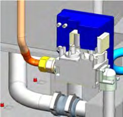
3E-490044NI – 03/20                               Page 1

1 - MANUTENTION / MANUTENTION / MANTENIMIENTO

FOURS 6 ET 10 NIVEAUX / 6 AND 10 LEVEL OVENS / KOMBIDÄMPFER 6 UND 10 EINSCHÜBE / HORNOS DE 6 Y 10 NIVELES

 A    Fig 1.1A

FOURS A 2 ENCEINTES / TWIN CAVITY OVENS / KOMBIDÄMPFER MIT ZWEI GARRÄUMEN / HORNOS DE DOS CÁMARAS

 A    Fig 1.2A

 B Fig 1.2B
      1                                           2

                                                       x4                      3

                                                                                   ELRO-Werke AG
                                                                                   Wohlerstrasse 47
                                                                                   5620 Bremgarten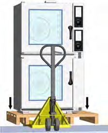
3E-490044NI – 03/20                             Page 2

 C Fig 1.2C
     1                                           2

      X5

FOURS 20 NIVEAUX / 20 LEVEL OVENS / KOMBIDÄMPFER 20 EINSCHÜBE / HORNOS DE 20 NIVELES

 A    Fig 1.3A

 B    Fig 1.3B

         1                                       2

                                                                              +

                                                                                  ELRO-Werke AG
                                                                                  Wohlerstrasse 47
                                                                                  5620 Bremgarten
3E-490044NI – 03/20   Page 3

 C Fig 1.3C
      1               2

                           x4   3

 D Fig 1.3D
     1                2

      X6

                                    ELRO-Werke AG
                                    Wohlerstrasse 47
                                    5620 Bremgarten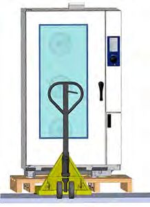
3E-490044NI – 03/20                              Page 4

2 - MISE EN PLACE / HANDLING / AUFSTELLUNG / COLOCACIÓN

FOURS 6 ET 10 NIVEAUX SUR SON PIETEMENT / 6 AND 10 LEVELS ON A STAND / KOMBIDÄMPFER 6 UND 10 EINSCHÜBE
AUF SEINEM UNTERGESTELL / HORNOS DE 6 Y 10 NIVELES EN SU BASE

 A    Fig 2.1A                                            B   Fig 2.1B

 C    Fig 2.1C

       1

                                                   2x
                                                                                         2
                                                   4x

                                                                                             ∅ 8 x 65

                                                                                 ELRO-Werke AG
                                                                                 Wohlerstrasse 47
                                                                                 5620 Bremgarten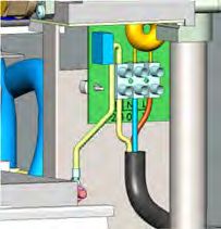
3E-490044NI – 03/20                              Page 5

FOURS 6 ET 10 NIVEAUX SUR TABLE / 6 AND 10 LEVELS ON A TABLE / KOMBIDÄMPFER 6 UND 10 EINSCHÜBE AUF DEM
TISH / HORNOS DE 6 Y 10 NIVELES EN TABLA

 A    Fig 2.2A

       1                                                     2

            4x

                                                                                 ELRO-Werke AG
                                                                                 Wohlerstrasse 47
                                                                                 5620 Bremgarten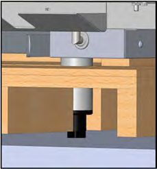
3E-490044NI – 03/20                            Page 6

FOURS A DEUX ENCEINTES / TWIN CAVITY OVENS / KOMBIDÄMPFER MIT ZWEI GARRÄUMEN / HORNOS DE DOS
CÁMARAS

 A    Fig 2.3A

 B    Fig 2.3B

        1

                                                                                     2x
                                                           2                         4x

                 1
                                                                                 ∅ 8 x 65

                                                                              ELRO-Werke AG
                                                                              Wohlerstrasse 47
                                                                              5620 Bremgarten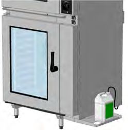
3E-490044NI – 03/20                             Page 7

FOURS 20 NIVEAUX / 20 LEVEL OVENS / KOMBIDÄMPFER 20 EINSCHÜBE / HORNOS DE 20 NIVELES

 A    Fig 2.3A

 B    Fig 2.3B

        1

                                                                                       1x
                                                         2
                                                                                       4x

                            1

                                                                      ∅ 8 x 65

                                                                                 ELRO-Werke AG
                                                                                 Wohlerstrasse 47
                                                                                 5620 Bremgarten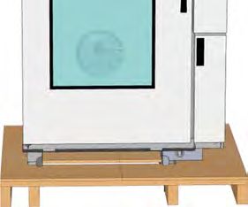
3E-490044NI – 03/20                              Page 8

3 - RACCORDEMENT EAU / WATER CONNECTION / WASSERANSCHLUSS / CONEXIÓN DE AGUA

 A    Fig 3A
   23°C / 75°F

                       Ø20/27
                       G3/4"

                                              AC061KI - AC101KI - AC20KI

                                                                           ByPass
                                                                                           §

     EA
     EN 13959
     CAa
     EN 14357

          Ø20/27      Ø20/27
          G3/4"       G3/4"

4 - RACCORDEMENT VIDANGE / DRAIN CONNECTION / ABLAUFANSCHLUSS / CONEXIÓN VACIADO

 A    Fig 4A

                                    AC061KI - AC101KI - AC20KI
                                                                                          OK

                                                                                               > 2.5°

                                ∅ 50mm

 > 2.5°                                         > 98°C

                                                                                    ELRO-Werke AG
                                                                                    Wohlerstrasse 47
                                                                                    5620 Bremgarten
3E-490044NI – 03/20 Page 9
5 - RACCORDEMENT ELECTRIQUE / ELECTRICAL CONNECTION / ELEKTRISCHER ANSCHLUSS / CONEXIÓN
ELÉCTRICA
A Fig 5A B Fig 5B
AC601KI*
AC101KI*
V Imax (A) mm² V Imax (A) mm²
EPJ061E 400V 3Na.c. 14,3 5G2.5 HO7RNF (3P+T+N) EPJ201E 400V 3Na.c. 42,4 5G10 HO7RNF (3P+T+N)
EPJ061E 230 3a.c. 27,3 4G6 HO7RNF (3P+T) EPJ201E 230 3a.c. 70,4 4G16 HO7RNF (3P+T)
EPJ061G 230 a.c. 1,3 3G2.5 HO7RNF (1P+T+N) EPJ201G 230 a.c. 3 3G2.5 HO7RNF (1P+T+N)
EPJ101E 400V 3Na.c. 23 5G4 HO7RNF (3P+T+N) EPJ202E 400V 3Na.c. 81,3 5G16 HO7RNF (3P+T+N)
EPJ101E 230 3a.c. 38,8 4G6 HO7RNF (3P+T) EPJ202E 230 3a.c. 138,2 4G35 HO7RNF (3P+T)
EPJ101G 230 a.c. 1,3 3G2.5 HO7RNF (1P+T+N) EPJ202G 230 a.c. 3 3G2.5 HO7RNF (1P+T+N)
EPJ102E 400V 3Na.c. 36,1 5G6 HO7RNF (3P+T+N) EPJ611E 400V 3Na.c. 37,4 5G6 HO7RNF (3P+T+N)
EPJ102E 230 3a.c. 61,4 4G10 HO7RNF (3P+T) EPJ611E 230 3a.c. 62,5 4G10 HO7RNF (3P+T)
EPJ102G 230 a.c. 1,3 3G2.5 HO7RNF (1P+T+N) EPJ661E 400V 3Na.c. 28,7 5G6 HO7RNF (3P+T+N)
EPJ661E 230 3a.c. 47,5 4G10 HO7RNF (3P+T)
C Fig 5C D Fig 5D
230V a.c 230V 3a.c 400V 3Na.c
ELRO-Werke AG
Wohlerstrasse 47
5620 Bremgarten3E-490044NI – 03/20 Page 10
6 - RACCORDEMENT GAZ / GAS CONNECTION / GASANSCHLUSS / CONEXIÓN GAS
A Fig 6A B Fig 6B
Ø15/21
G 1/2"
C Fig 6C
1 P in = Pmbar ± 1 mbar
2
6/10 20
Precijet+ Precijet+
P in
P in
D Fig 6D
1
2 8 mbar ≤ P out ≤ 11 mbar
6/10 20
Precijet+ Precijet+
P out
P out
ELRO-Werke AG
Wohlerstrasse 47
5620 Bremgarten3E-490044NI – 03/20 Page 11
7 - RACCORDEMENT PRODUIT DE NETTOYAGE / CLEANING PRODUCT CONNECTION / ANSCHLUSS
REINIGUNGSMITTEL / CONEXIÓN PRODUCTO DE LIMPIEZA
A Fig 7A
B Fig 6B
8 - CONSIGNES MANIPULATION PLATS CHAUDS / GUIDELINES FOR HOT CONTAINERS /
SICHERHEITSHINWEISE ZUM HANDLING HEIßER BEHÄLTER / INSTRUCCIONES MANIPULACIÓN PLATOS
CALIENTES
A Fig 8A
1x
ELRO-Werke AG
Wohlerstrasse 47
5620 Bremgarten3E-490044NI – 03/20 Page 12
9 - SUPPORT POIGNEE DE CHARIOT 20 NIVEAUX / THE 20 LEVELS TROLLEY HANDLE SUPPORT / DER RACK-
GRIFFHALTERUNG 20 EINSCHÜBE / SOPORTE DE MANIJA DE CARRETILLA DE 20 NIVELES
A
3
1
2
1x
3x
B
ELRO-Werke AG
Wohlerstrasse 47
5620 Bremgarten3E-490044NI – 03/20 Page 13
CARACTÉRISTIQUES TECHNIQUES / TECHNICAL CHARACTERISTICS / TECHNISCHE DATEN /
CARACTERÍSTICAS TÉCNICAS
CODE Designation Designation Bezeichnung Designation Energie Energy Energie Energia
EPJ061E ELRO:Precijet 6 Niveaux GN1/1 (Elec) ELRO:Precijet 6 Levels GN1/1 (Elec) ELRO:Precijet 6 Ebenen GN1/1 (Elek) ELRO:Precijet 6 Niveles GN1/1 (Eléc) Electrique Electric Elektrisch Eléctrica
EPJ061E ELRO:Precijet 6 Niveaux GN1/1 (Elec) ELRO:Precijet 6 Levels GN1/1 (Elec) ELRO:Precijet 6 Ebenen GN1/1 (Elek) ELRO:Precijet 6 Niveles GN1/1 (Eléc) Electrique Electric Elektrisch Eléctrica
EPJ061G ELRO:Precijet 6 Niveaux GN1/1 (Gaz) ELRO:Precijet 6 Levels GN1/1 (Gas) ELRO:Precijet 6 Ebenen GN1/1 (Gas) ELRO:Precijet 6 Niveles GN1/1 (Gas) Gaz Gas Gas Gas
EPJ101E ELRO:Precijet 10 Niveaux GN1/1 (Elec) ELRO:Precijet 10 Levels GN1/1 (Elec) ELRO:Precijet 10 Ebenen GN1/1 (Elek) ELRO:Precijet 10 Niveles GN1/1 (Eléc) Electrique Electric Elektrisch Eléctrica
EPJ101E ELRO:Precijet 10 Niveaux GN1/1 (Elec) ELRO:Precijet 10 Levels GN1/1 (Elec) ELRO:Precijet 10 Ebenen GN1/1 (Elek) ELRO:Precijet 10 Niveles GN1/1 (Eléc) Electrique Electric Elektrisch Eléctrica
EPJ101G ELRO:Precijet 10 Niveaux GN1/1 (Gaz) ELRO:Precijet 10 Levels GN1/1 (Gas) ELRO:Precijet 10 Ebenen GN1/1 (Gas) ELRO:Precijet 10 Niveles GN1/1 (Gas) Gaz Gas Gas Gas
EPJ102E ELRO:Precijet 10 Niveaux GN2/1 (Elec) ELRO:Precijet 10 Levels GN2/1 (Elec) ELRO:Precijet 10 Ebenen GN2/1 (Elek) ELRO:Precijet 10 Niveles GN2/1 (Eléc) Electrique Electric Elektrisch Eléctrica
EPJ102E ELRO:Precijet 10 Niveaux GN2/1 (Elec) ELRO:Precijet 10 Levels GN2/1 (Elec) ELRO:Precijet 10 Ebenen GN2/1 (Elek) ELRO:Precijet 10 Niveles GN2/1 (Eléc) Electrique Electric Elektrisch Eléctrica
EPJ102G ELRO:Precijet 10 Niveaux GN2/1 (Gaz) ELRO:Precijet 10 Levels GN2/1 (Gas) ELRO:Precijet 10 Ebenen GN2/1 (Gas) ELRO:Precijet 10 Niveles GN2/1 (Gas) Gaz Gas Gas Gas
EPJ201E ELRO:Precijet 20 Niveaux GN1/1 (Elec) ELRO:Precijet 20 Levels GN1/1 (Elec) ELRO:Precijet 20 Ebenen GN1/1 (Elek) ELRO:Precijet 20 Niveles GN1/1 (Eléc) Electrique Electric Elektrisch Eléctrica
EPJ201E ELRO:Precijet 20 Niveaux GN1/1 (Elec) ELRO:Precijet 20 Levels GN1/1 (Elec) ELRO:Precijet 20 Ebenen GN1/1 (Elek) ELRO:Precijet 20 Niveles GN1/1 (Eléc) Electrique Electric Elektrisch Eléctrica
EPJ201G ELRO:Precijet 20 Niveaux GN1/1 (Gaz) ELRO:Precijet 20 Levels GN1/1 (Gas) ELRO:Precijet 20 Ebenen GN1/1 (Gas) ELRO:Precijet 20 Niveles GN1/1 (Gas) Gaz Gas Gas Gas
EPJ202E ELRO:Precijet 20 Niveaux GN2/1 (Elec) ELRO:Precijet 20 Levels GN2/1 (Elec) ELRO:Precijet 20 Ebenen GN2/1 (Elek) ELRO:Precijet 20 Niveles GN2/1 (Eléc) Electrique Electric Elektrisch Eléctrica
EPJ202E ELRO:Precijet 20 Niveaux GN2/1 (Elec) ELRO:Precijet 20 Levels GN2/1 (Elec) ELRO:Precijet 20 Ebenen GN2/1 (Elek) ELRO:Precijet 20 Niveles GN2/1 (Eléc) Electrique Electric Elektrisch Eléctrica
EPJ202G ELRO:Precijet 20 Niveaux GN2/1 (Gaz) ELRO:Precijet 20 Levels GN2/1 (Gas) ELRO:Precijet 20 Ebenen GN2/1 (Gas) ELRO:Precijet 20 Niveles GN2/1 (Gas) Gaz Gas Gas Gas
EPJ611E ELRO:Precijet 6 sur 10 Niveaux GN1/1 (Elec) ELRO:Precijet 6 on 10 Levels GN1/1 (Elec) ELRO:Precijet 6 von 10 Ebenen GN1/1 (Elek) ELRO:Precijet 6 de 10 Niveles GN1/1 (Eléc) Electrique Electric Elektrisch Eléctrica
EPJ611E ELRO:Precijet 6 sur 10 Niveaux GN1/1 (Elec) ELRO:Precijet 6 on 10 Levels GN1/1 (Elec) ELRO:Precijet 6 von 10 Ebenen GN1/1 (Elek) ELRO:Precijet 6 de 10 Niveles GN1/1 (Eléc) Electrique Electric Elektrisch Eléctrica
EPJ661E ELRO:Precijet 6 sur 6 Niveaux GN1/1 (Elec) ELRO:Precijet 6 on 6 Levels GN1/1 (Elec) ELRO:Precijet 6 von 6 Ebenen GN1/1 (Elek) ELRO:Precijet 6 de 6 Niveles GN1/1 (Eléc) Electrique Electric Elektrisch Eléctrica
EPJ661E ELRO:Precijet 6 sur 6 Niveaux GN1/1 (Elec) ELRO:Precijet 6 on 6 Levels GN1/1 (Elec) ELRO:Precijet 6 von 6 Ebenen GN1/1 (Elek) ELRO:Precijet 6 de 6 Niveles GN1/1 (Eléc) Electrique Electric Elektrisch Eléctrica
Débit gaz / Gas flow / Gasdurchsatz / Flujo Poids / Weight / Dimensions / Maße / Dimensiones (mm)
KwG G31 37/50 G30 28/50 G20 20 G25 20 G25 25 Gewicht / Peso Avancée / Depth / Largeur / Width / Hauteur / High /
CODE U Lib KwE Imax (A)
kW Kg/h Kg/h m3/h m3/h m3/h (Kg) Tiefe / Profundidad Breite / Anchura Höhe / Altura
EPJ061E 400 3Na.c. 9,3 14,3 - - - - - - 108 846 920 899
EPJ061E 230 3a.c. 9,3 27,3 - - - - - - 108 846 920 899
EPJ061G 230 a.c. 0,3 1,3 23,00 1,79 1,81 2,43 2,76 2,76 123 846 920 899
EPJ101E 400 3Na.c. 15,3 23,0 - - - - - - 121 846 920 1069
EPJ101E 230 3a.c. 15,3 38,8 - - - - - - 121 846 920 1069
EPJ101G 230 a.c. 0,3 1,3 23,00 1,79 1,81 2,43 2,76 2,76 136 846 920 1069
EPJ102E 400 3Na.c. 24,3 36,1 - - - - - - 144 1171 920 1069
EPJ102E 230 3a.c. 24,3 61,4 - - - - - - 144 1171 920 1069
EPJ102G 230 a.c. 0,3 1,3 23,00 1,79 1,81 2,43 2,76 2,76 159 1171 920 1069
EPJ201E 400 3Na.c. 27,7 42,4 - - - - - - 274 862 990 1947
EPJ201E 230 3a.c. 27,7 70,4 - - - - - - 274 862 990 1947
EPJ201G 230 a.c. 0,7 3 45,50 3,54 3,59 4,81 5,47 5,47 291 862 990 1947
EPJ202E 400 3Na.c. 54,7 81,3 - - - - - - 326 1187 990 1947
EPJ202E 230 3a.c. 54,7 138,2 - - - - - - 326 1187 990 1947
EPJ202G 230 a.c. 0,7 3 45,50 3,54 3,59 4,81 5,47 5,47 342 1187 990 1947
EPJ611E 400 3Na.c. 24,6 37,4 - - - - - - 226 887 920 1930
EPJ611E 230 3a.c. 24,6 62,5 - - - - - - 226 887 920 1930
EPJ661E 400 3Na.c. 18,6 28,7 - - - - - - 207 887 920 1970
EPJ661E 230 3a.c. 18,6 47,5 - - - - - - 207 887 920 1970
Le niveau de pression acoustique pondéré A est inférieur à 70 dB(A). / The balanced acoustic pressure level A is less than 70 dB(A). / Der A-
bewertete Schalldruckpegel liegt unter 70 dB(A). / El nivel de presión acústica ponderado es inferior a 70 dB (A).
ELRO-Werke AG
Wohlerstrasse 47
5620 Bremgarten3E-490044NI – 03/20 Page 14
PLAQUE SIGNALETIQUE / DATA PLATE / TYPENSCHILD / PLACA DE IDENTIFICACIÓN
Pour toute correspondance relative à votre matériel, rappeler toujours / In any correspondence about your equipment, please indicate / Bei
jeder Kontaktaufnahme mit dem Kundendienst in Zusammenhang mit Ihrem Gerät, bitten wir Sie folgende Angaben bereit zu halten / Para cualquier
correspondencia relativa a su material recuerde:
- Le numéro de modèle (Model.) / The model number / Modellnummer / El número de modelo
- Le numéro de série (Fabr. Nr) / The serial number / Seriennummer / El número de serie
- La date (date) / The date / Datum / La fecha
La plaque signalétique, quel que soit le four, se trouve apposée sur le coté droit du four, dans le coin inférieur gauche. / The data plate, on all
ovens, is fixed onto the right side of the oven in the lower left corner. / Unabhängig vom Kombidämpfermodell befindet sich das Typenschild auf der
rechten Seite des Kombidämpfer in der unteren linken Ecke. / La placa de identificación de todos los hornos se encuentra en el lado derecho del
horno, en la esquina inferior izquierda.
FOURS ELECTRIQUES / ELECTRIC OVENS / ELEKTROGERÄTE /
HORNOS ELÉCTRICOS
ZI route de Dole
39800 POLIGNY
Emplacement de la plaque signalétique / Location of the data plate /
Position des Typenschilds / Ubicación de la placa de identificación
FOURS GAZ / GAS OVENS / GASGERÄTE / HORNOS DE GAS
ZI route de Dole
39800 POLIGNY
Emplacement des plaques / Location of the data plates
Position der Typenschilder / Ubicación de las placas
Plaque changement de gaz / Gas changing plate / Schild Gasart La case marquée d'une croix, indique le gaz pour lequel est réglé l'appareil / The box
/ Placa de cambio de gas marked with a cross Indicates the gas for which the appliance has been adjusted /
Das angekreuzte Feld gibt die Gasart an, auf die das Gerät eingestellt ist / La casilla
marcada con una cruz indica el gas para el que está ajustado el aparato.
Une seconde plaque est apposée à proximité de la plaque
signalétique, et indique / A second plate is fixed next to the data
plate which indicates / Ein zweites Schild neben dem Typenschild
enthält folgende Angaben / Cerca de la placa de identificación hay
una segunda placa que indica:
- Le gaz pour lequel l'appareil est réglé / The gas for which the
appliance has been adjusted / Die Gasart, auf die der
Kombidämpfer eingestellt ist / El gas para el que está ajustado
el aparato
- Le pays de destination / The country(ies) of destination / Das
Bestimmungsland / El país de destino Pays de destination de l'appareil / Country of destination of the appliance /
Bestimmungsland des Kombidämpfers / País de destino del aparato
EN CAS DE CHANGEMENT DE GAZ ( Voir Paragraphe: Adaptation de l'appareil d'un gaz à un autre), Remplacer cette plaque, et cocher
le nouveau gaz utilisé. / IN CASE OF A CHANGE OF GAS (See Section: Changing the appliance from one gas to another) Modify this
plate, and mark the new gas used. / BEI WECHSEL DER GASART (Siehe Abschnitt: Anpassung des Geräts an eine andere Gasart) muss
dieses Schild ausgetauscht und die neue, verwendete Gasart angekreuzt werden / EN CASO DE CAMBIO DE GAS (Véase párrafo:
Adaptación del aparato de un gas a otro), Cambie esta placa y marque con una cruz el nuevo gas utilizado.
RENSEIGNER la zone "Pays" par le nom du pays où est installé le produit. / Fill in the "Pays" zone with the name of the country where the
appliance is installed. / FÜLLEN Sie das Feld „Pays" mit dem Namen des Landes aus, wo das Gerät aufgestellt wird. / INTRODUCIR en la
zona "País" el nombre del país donde está instalado el producto.
NOTA: Le couple Gaz/Pression pour lequel l'appareil est réglé, doit être autorisé dans le pays concerné. Vérifier ce point dans le
paragraphe: Adaptation de l'appareil d'un gaz à un autre. / NOTE: Both the Gas and Pressure for which the appliance is set must be
authorised in the country in question. Check this point in the section: Changing the appliance from one gas to another. / HINWEIS: Die
Gas- und Druckwerte, auf die das Gerät eingestellt ist, müssen im betreffenden Land zugelassen sein. Bitte prüfen Sie diesen Punkt im
Abschnitt: Anpassung des Geräts an eine andere Gasart. / NOTA: El par gas/presión para el que está ajustado el aparato debe
autorizarse en el país concernido. Verifique este punto en el párrafo. Adaptación de un aparato de gas a otro.
ELRO-Werke AG
Wohlerstrasse 47
5620 Bremgarten3E-490044NI – 03/20 Page 15
ADAPTATION DE L'APPAREIL D'UN GAZ A UN AUTRE / CHANGING THE APPLIANCE FROM ONE GAS TO
ANOTHER / ANPASSUNG DES GERÄTS AN EINE ANDERE GASART / ADAPTACIÓN DEL APARATO DE UN
GAS A OTRO
Généralités / General / Allgemeines / Generalidades::
Dans les chapitres qui suivent, les différents gaz sont référencés par leur codification internationale / In the following chapters, the different
gases are designated by their international codification / In den folgenden Kapiteln sind die verschiedenen Gasarten gemäß ihrer internationalen
Kodifizierung verzeichnet / En los siguientes capítulos se hace referencia a los diferentes gases por su codificación nacional:
GAZ NATUREL Groupe H, (Méthane, Gaz de Lacq) / NATURAL GAS Group H, (Methane, Lacq gas) / ERDGAS Gruppe H,
G 20
(Methan, Gas aus Lacq) / GAS NATURAL Grupo H, (metano, gas de Lacq)
GAZ NATUREL Groupe L, (Gaz type Groningue) / NATURAL Group L, (Groningue type gas) / ERDGAS Gruppe L, (Gas der Art
G 25
Groningen) / GAS NATURAL Grupo L (gas tipo Groningue)
GAZ NATUREL Groupe K, (Pays Bas) / NATURAL Group K, (The Netherlands) / ERDGAS Gruppe K, (Niederlande) / GAS
G 25.3
NATURAL Grupo K (Países Bajos)
G 30 BUTANE / BUTAN / BUTANO
G 31 PROPANE / PROPAN / PROPANO
LISTE DES GAZ / PRESSIONS AUTORISEES SELON LES CATEGORIES ET PAYS / LIST OF AUTHORISED GASES/PRESSURES
ACCORDING TO CATEGORIES AND COUNTRIES / LISTE DER GASARTEN / ZUGELASSENER DRUCK NACH KATEGORIE UND
LAND / LISTA DE GASES /PRESIONES AUTORIZADAS DE ACUERDO CON LAS CATEGORÍAS Y EL PAÍS
Pays / Country / Land / País Catégorie / Categories / Gaz / Gas / Gas Pression / Pressure /
Kategorie / Categoría Druck / Presión (mbar)
Autriche / Austria / Österreich / Austria I2H G20 20
I3B/P G30 / G31 50
I3P G31 50
Finlande / Finland / Finnland / Finlandia I2H
G20 20
Danemark / Denmark / Dänemark / Dinamarca
Suède / Sweden / Schweden / Suède I3B/P
G30 et G31 30
Norvège / Norway / Norwegen / Noruega
République Tchèque / Czech republic / I2H G20 20
Tschechische Republik / República checa I3B/P G30 / G31 30
I3+ G30 / G31 28-30 / 37
I3P G31 37 / 50
Espagne / Spain / Spanien / España I2H G20 20
Royaume Uni / United Kingdom / Vereinigtes I3+ G30 / G31 28-30 / 37
Königreich / Reino Unido I3P G31 37 / 50
Allemagne / Germany / Deutschland / Alemania G20 20
Luxembourg / Luxembourg / Luxemburg / I2ELL G25 20
Luxemburgo I3B/P G30 / G31 30
I3P G31 50
Suisse / Switzerland / Schweiz / Suiza I2H G20 20
I3B/P G30 et G31 50
I3+ G30 / G31 28-30 / 37
I3P G31 37 / 50
Grèce / Greece / Griechenland / Grecia I2H G20 20
Italie / Italy / Italien / Italia I3B/P G30 / G31 30
I3+ G30 / G31 28-30 / 37
I3P G31 37
Irlande / Ireland / Irland / Irlanda I2H G20 20
Portugal / Portugal I3+ G30 / G31 28-30 / 37
I3P G31 37
Pays Bas / The Netherlands / Niederlande / Países Bajos I2EK G20 20
G25.3 25
I3B/P G30 / G31 30
I3P G31 50
France / Frankreich / Francia G20 20
I2Esi
G25 25
I3+ G30 / G31 28-30 / 37
I3P G31 37 / 50
Belgique / Belgium / Belgien / Bélgica I2E(s)B G20 / G25 20 / 25
I3+ G30 / G31 28-30 / 37
I3P G31 37
PASSAGE D'UN GAZ A UN AUTRE / CHANGING FROM ONE GAS TO ANOTHER / WECHSEL DER GASART / PASO DE UN
GAS A OTRO
Le changement de gaz passant par le changement de catégorie est à réaliser uniquement sous la responsabilité de notre
représentant local. Voir notice de maintenance. / A change of gas that entails a change of category can only be made under the
ELRO-Werke AG
Wohlerstrasse 47
5620 Bremgarten3E-490044NI – 03/20 Page 16
responsibility of our company or local agent. See maintenance manual. / Der Wechsel der Gasart und der Kategorie darf nur unter der
Verantwortung unserer örtlichen Vertreters erfolgen. Siehe Wartungsanleitung. / El cambio de gas pasando por el cambio de categoría solo
se puede realizar bajo la responsabilidad de nuestro representante local. Véase manual de mantenimiento.
DEBITS GAZ ET PUISSANCES / GAS FLOW RATES AND POWERS / GASMENGEN UND LEISTUNGEN / CAUDALES DE GAS
Y POTENCIAS
Voir paragraphe : Caractéristiques techniques / See section : Technical characteristics / Siehe Abschnitt : Technische Daten / Ver
párrafo: Características técnicas
TABLEAU DES INJECTEURS / CHART OF GAS JETS / ÜBERSICHT DER DÜSEN / TABLA DE LOS INYECTORES
Fours 6 et 10 niveaux / 6 and 10 level ovens / Kombidämpfer 6 & 10 Einschübe / Hornos de 6 y 10 niveles
Repérage des injecteurs /
Identification of jets /
GAZ / GAS / GAS INJECTEURS / JETS / DÜSEN / Kennzeichnung der Düsen /
INYECTORES Identificación de inyectores
Dénomination / Designation / Pression / Pressure / Nbre / Qty / Code / Código
Bezeichnung / Denominación Druck / Presión Anzahl / Número ∅
e/th
Famille / Family / Type / Typ (mbar) (1/100 )
Familie / Familia / Tipo
Brûleur / Gaz naturel / Natural G20 20 1 500 148 560
Burner / gas / Erdgas / Gas G25 20 1 625 148 568
Brenner / natural G25.3 25 1 625 148 568
Quemador G.P.L. / L.P.G. / G31 30 1 360 148 563
G.P.L. G31 37 1 360 148 563
G31 50 1 360 148 563
G30 30 1 335 148 562
G30 50 1 335 148 562
∅
Fours 20 niveaux / 20 level ovens / Kombidämpfer 20 Einschübe / Hornos de 20 niveles
GAZ / GAS / GAS INJECTEURS / JETS / DÜSEN / INYECTORES
Dénomination / Designation / Pression / Pressure Nbre / Qty / Nbre / Qty / Code /
Bezeichnung / Denominación / Druck / Presión Anzahl / Número Anzahl / Número ∅ Código
Famille / Family / Type / Typ (mbar) Sèche / dry / Vapeur / steam / (1/100e/th)
Familie / Familia / Tipo Heißluft / Seco Dampf / Vapor
Brûleur / Gaz naturel / Natural G20 20 2 1 500 148 560
Burner / gas / Erdgas / Gas G25 20 2 1 625 148 568
Brenner / natural G25.3 25 2 1 625 148 568
Quemador G.P.L. / L.P.G. / G31 30 2 1 360 148 563
G.P.L. G31 37 2 1 360 148 563
G31 50 2 1 360 148 563
G30 30 2 1 335 148 562
G30 50 2 1 335 148 562
Position injecteur et entretoise bague d’air / Positioning of the jets and the air distancing ring /
Position Düse und Abstandsstück Luftring / Posición inyector y anillo espaciador de aire
Entretoise bague d’air / Air
distance ring / Abstandsstück
Luftring / Aire anillo espaciador
Injecteur / Nozzle /
Düse / Inyector
Vanne de régulation /
Regulating valve /
Regelventil / válvula de
control
ELRO-Werke AG
Wohlerstrasse 47
5620 Bremgarten3E-490044NI – 03/20 Page 1 FR
REGLAGE DES PARAMETRES
FREQUENCE INTERVENTION MAINTEANCE ET TAUX D’UTILISATION PAR JOUR
- Rentrer dans l’onglet service
- Sélectionner la touche “Paramètres d’installation”
- Rentrer le code PIN d’installateur “INSB”
- Valider “V”: A la fin de la saisie, si le code est correct, accès au menu sinon retour à la saisie du code PIN.
- Rentrer le nombre d'heure avant la prochaine maintenance (1500h par défaut) : « HSr ». Réglable de 100 à 5000 heures. Prévoir impérativement
au minimum une révision par an.
* Sélectionner la zone de valeur à modifier
* Régler la valeur à l’aide du codeur.
- Rentrer le taux d'utilisation moyen de l'appareil en nombre d'heure par jour : « H-J ». Réglable de 1 à 24 heures.
* Sélectionner la zone de valeur à modifier
* Régler la valeur à l’aide du codeur
Frequence de maintenance
Taux d’utilisation par jour en heure
CAPACITE TRAITEMENT D’EAU
Ce compteur est valable uniquement si le four est alimenté par 2 réseaux d’eau séparés.
- Rentrer dans l’onglet service
- Sélectionner la touche “Paramètres client”
- Rentrer le code PIN “CHEF” Mot de passe « permanent » (minuscule ou majuscule)
- Valider “V”: A la fin de la saisie, si le code est correct, accès au menu sinon retour à la saisie du code PIN.
- Modifier ou renseigner la valeur de la capacité du système de traitement d’eau (capacité en litre). Réglé à zéro par défaut (si pas de traitement
de l'eau dédié au four).
* Sélectionner la zone de valeur à modifier
* Régler la valeur à l’aide du codeur.
- Réinitialiser le compteur si nécessaire.
* Appuyer sur la zone « RESET »
* Confirmer en appuyant sur la touche « OUI »
La capacité en litres du système de traitement de l'eau.
Réinitialiser. Réglé à zéro par défaut (si pas de traitement
de l'eau dédié au four)
ELRO-Werke AG
Wohlerstrasse 47
5620 Bremgarten3E-490044NI – 03/20 Page 2 FR
EXIGENCES GENERALES
GARANTIE.
Pour nous permettre de vous assurer la garantie de ces équipements, nous vous engageons à respecter les SPECIFICATIONS
CONSTRUCTEUR, consignées dans le présent manuel.
Si toutefois, vous n'étiez pas en mesure d'assurer l'entretien et la maintenance demandés, notre réseau d'installation et de service de proximité
se tient à votre entière disposition pour vous étudier un contrat personnalisé.
AVERTISSEMENT
- Le produit qui vous est livré est en conformité avec les normes en vigueur. En cas de transformation, l'intervenant endosse la
responsabilité de constructeur. Le constructeur ne saurait être responsable en cas d'utilisation à des fins autres que celles pour lesquelles
la machine est conçue.
- Il est impératif de laisser l'appareil sur son socle lors des manipulations jusqu'à l'implantation définitive.
- Appareils à usage seulement professionnel, doivent être utilisés par du personnel qualifié.
- Lire attentivement ce document avant l'installation.
- Conserver vos documents.
- Notice originale.
L'installation, la modification ou la réparation de l'appareil doit être effectuée selon les règles de l'art par un installateur et réparateur qualifié.
Ces appareils doivent être installés avec une ventilation suffisante pour empêcher la formation de concentrations inadmissibles de substances
nocives pour la santé dans le local dans lequel ils sont installés.
L'appareil est de TYPE A (-non raccordé à un conduit d'évacuation des produits de combustion).
Le débit d'air neuf requis pour l'alimentation en air de combustion est de 2 m3/h par kW de débit calorifique.
Les cheminées d’évacuation des vapeurs, ne peuvent être raccordés étanche à une hotte ou à un conduit d’évacuation.
Si ces appareils sont installés en position adossée contre une cloison ou un mur, ceux-ci devront être réalisés en matériaux non combustibles
ou, si ce n'est pas le cas, devront être recouverts d'un matériau approprié, bon isolant, non combustible.
Respecter les distances minimums imposées entre l’appareil et une paroi (mur ou autres appareils de cuisson) (4 cm à gauche, 50 cm à droite).
Ne pas placer de source de chaleur contre le côté droit des fours 6 et 10 niveaux.
Sauf indications contraires spécifiées, les parties protégées par le fabricant ou son mandataire ne doivent pas être manipulées par l'installateur.
Le constructeur déclare que l'emballage est conforme à la directive 94/62/CE (directive emballages et déchets d’emballages du 20.12.94) et
invite l'installateur (et l'utilisateur) à respecter les règles relatives à l'enlèvement des emballages (recyclage ou revalorisation).
Respecter les règlementations et normes en vigueur du lieu de montage concernant les connexions d'eau, d'électricité, de vidange, ... de
l'appareil.
ATTENTION - Débranchez l’appareil du réseau électrique avant toute intervention de maintenance.
Ne jamais placer de bidon de produit détartrant pour l'introduction automatique de produit. Cela endommagerait le circuit hydraulique de votre
four de manière irréversible.
Afin de garantir un résultat de nettoyage optimum sans risque d’attaque chimique, nous recommandons l’utilisation de notre produit de
nettoyage BK101. L’utilisation d’un autre produit est possible. D’une manière générale, les produits de nettoyage compatibles avec nos fours
doivent :
- Avoir une composition basée sur l’hydroxyde de potassium avec une concentration < 25%, SANS hydroxyde de sodium
- Etre compatible avec une température d’utilisation de 60°C.
- Comporter des agents anticorrosion
Rappel des phases de risques conformément à la fiche sécurité de chaque produit nettoyant et détartrant
- Nocif en cas d’ingestion.
- Provoque de graves brûlures.
- Irritant pour les yeux / Irritant pour les voies respiratoires.
- Risques de lésions oculaires graves.
Danger d’irritation de la peau et des yeux ou de brûlures par acide.
Les nettoyants et détartrants irritent la peau et les yeux en cas de contact direct et peuvent provoquer des brûlures en cas de contact direct.
- Ne pas inhaler le brouillard pulvérisé
- Ne pas mettre les nettoyants et détartrants en contact avec les yeux et la peau
- N’ouvrez en aucun cas la porte de l’appareil pendant le nettoyage automatique
- Porter des vêtements de protection, des gants de protection et des lunettes de protection hermétique conformément à la fiche sécurité.
Rappel des phases de sécurité conformément à la fiche sécurité de chaque produit nettoyant et détartrant
- Ne pas manger et ne pas boire pendant l’utilisation.
- Ne pas respirer les vapeurs.
- Si contact avec les yeux, laver immédiatement et abondamment avec de l’eau et consulter un spécialiste.
- Porter un vêtement de protection approprié, des gants et un appareil de protection des yeux/du visage.
- En cas d’accident ou de malaise, consulter immédiatement un médecin
- Eliminer le produit et son récipient comme un déchet dangereux.
Le constructeur dégage toute responsabilité dans le cas où les instructions ci-dessus ne seraient pas respectées
La manutention ne doit être effectuée qu'avec des engins de levage adaptés. Si l'appareil doit être transporté, il doit l'être sur sa palette d'origine
et ne doit en aucun cas être superposé à d'autres appareils. Lors d'un déplacement et en l'absence de sa palette, l'appareil doit être porté et
non tiré. Fig. 1.1A, 1.2A-B-C, 1.3A-B-C-D.
ELRO-Werke AG
Wohlerstrasse 47
5620 Bremgarten3E-490044NI – 03/20 Page 3 FR
MISE EN PLACE
FOURS 6 ET 10 NIVEAUX SUR SON PIETEMENT
La hauteur du seuil de chargement impératif est de 900mm. Fig. 2.1B
Si le four est équipé d’une hotte : il est obligatoire de fixer le four au sol. Le piétement doit être fixé au sol à l’aide des 2 embases inox de
fixation fournies avec le piètement. Positionner les deux embases sur les pieds arrières du piètement. Fig. 2.1C
FOURS A DEUX ENCEINTES
La hauteur du seuil de chargement impératif est de 290mm sur fours 6+6 et 6+10. Fig. 2.2A
Si le four est équipé d’une hotte : il est obligatoire de fixer le four au sol. Le four doit être fixé au sol à l’aide des 2 embases inox de fixation
fournies avec le four. Positionner les deux embases sur les pieds arrière du four. Fig. 2.2B
FOURS 20 NIVEAUX
La hauteur du seuil de chargement impératif est de 355mm. Fig. 2.3A
Four 20 niveaux GN1/1 : il est obligatoire de fixer le four au sol. Le four doit être fixé au sol à l’aide d’une embase inox de fixation fournie avec
le four. Positionner l’embase sur le pied arrière gauche du four. Fig. 2.3B
CONSIGNES MANIPULATION PLATS CHAUDS
La hauteur de travail maximale au niveau supérieure est de 1600mm, de ce faite, une étiquette de danger plaque chaude est livrée avec les
notices. Coller cette étiquette sur le four à 1600 mm du sol. Fig. 8A
Attention: Lorsque les récipients sont remplis de liquide ou d’aliments qui se liquéfient pendant la cuisson, l’opérateur doit absolument
encore voir le contenu du récipient inséré le plus élevé.
RACCORDEMENTS
RACCORDEMENT ELECTRIQUE
Un moyen de déconnexion doit être prévu dans les canalisations fixes conformément aux règles d’installation, équipé d'un système à
verrouillage en position de sectionnement (permettant de réaliser une consignation).
L'installation doit être conforme aux textes réglementaires nationaux en vigueur. L'appareil doit être raccordé à la terre.
Les instructions doivent fournir les recommandations concernant les caractéristiques et le type des dispositifs de protection
supplémentaires à installer, tels qu'un ou des dispositifs à courant différentiel résiduel.
Le raccordement électrique se fait à l'arrière droit de l’appareil quel que soit le modèle. Fig. 5A-B
- Démonter le côté droit de l’appareil.
- Passer le câble par le presse étoupe.
- Brancher les fils (respecter Neutre et Terre).
- Serrer le presse étoupe.
- Remettre en place le côté droit de l’appareil.
- Brancher la liaison équipotentielle sur la borne prévue à cet effet. Fig. 5D
• N'utiliser que les câbles d'alimentation de type H07 RN-F d’une section en fonction de l’intensité du matériel (voir chapitre « caractéristiques
techniques » qui donne cette indication).
Prévoir un dispositif de séparation omnipolaire homologué pour la sécurité des personnes, (ayant une distance d'ouverture des contacts d'au
moins 3 mm).
RACCORDEMENT ECONOMISEUR D'ENERGIE
Fours 6 et 10 niveaux (option)
N'utiliser que des câbles d'alimentation de type HO 7 RNF de section 5 x 1.5 mm2. Prévoir à proximité de l'appareil, un dispositif de séparation
de tous les conducteurs de l'économiseur d'énergie homologué par la sécurité des personnes (ayant une distance d'ouverture des contacts d'au moins
3 mm). Des tensions dangereuses peuvent être présentes dans l'appareil en cas de défauts d'isolement.
Raccordement de l’économiseur d’énergie sur four 20 niveaux:
L’installation doit être conforme aux textes réglementaire nationaux en vigueur (France : NFC 15-100). Utiliser des câbles de type H07 RN-F
de section 1.5mm² avec le nombre de conducteur requis par l’économiseur d’énergie. Faire passer le ou les câbles dans le ou les presse-étoupe du
bornier et dans les passe-tôles de la platine électrique :
Retirer les ponts entre B1-C1 et B2-C2 et connecter l’économiseur sur les entrées sorties correspondantes.
ELRO-Werke AG
Wohlerstrasse 47
5620 Bremgarten3E-490044NI – 03/20 Page 4 FR
A: Information de sortie du four = Marche/Arrêt
B1 : Information de sortie du four : demande de puissance chauffe sèche
C1 : Information d’entrée : attribution de puissance ou non par l’économiseur pour la chauffe sèche
B2 : Information de sortie du four : demande de puissance chauffe vapeur
C2 : Information d’entrée : attribution de puissance ou non par l’économiseur pour la chauffe vapeur
D: Neutre
PE : Borne de masse
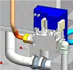
RACCORDEMENT GAZ
Vérifier que les réglages de l'appareil correspondent à la nature et à la pression du gaz distribué dans l'installation. (Voir paragraphe: Plaque
signalétique).
Raccorder l'appareil à la canalisation d'amenée de gaz en interposant une vanne de barrage permettant d'isoler l'appareil du reste de
l'installation. Fig. 6B
VERIFICATION DE LA PRESSION DE RACCORDEMENT Fig. 6C
Pour vérifier la pression d'alimentation en gaz de l'appareil, il suffit de brancher un manomètre à colonne d'eau sur la prise de pression,
lorsque le brûleur est en fonctionnement.
La pression de gaz ainsi mesurée doit être égale à celle indiquée sur la plaque signalétique pour le gaz utilisé (Voir paragraphe: Plaque
signalétique).
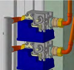
Pression de sortie gaz aux injecteurs en fonctionnement (P out) Fig. 6D
Celle-ci doit se situer entre 8 et 11 mbar. Utiliser un moyen de contrôle étalonné et suffisamment précis.
En cas de valeurs incohérentes, ne pas modifier le réglage de la vanne mais procéder à son remplacement.
Raccordement flexible:
Solution conseillée: Fours 6 / 10 niveaux: Flexible gaz agréé NF (type "TUBOGAZ" longueur 0.75 m, ∅ 15/21 (1/2") sans raccord flexible
qui doit être périodiquement examiné et remplacé si nécessaire.
RACCORDEMENT EAU
- Afin d’assurer la protection du réseau d’eau et de se conformer à la réglementation en vigueur, il est impératif de connecter l’appareil au
réseau d’eau via un dispositif de protection antipollution de type CAa (Fours équipés de la fonction lavage automatique avec prise en charge
du produit par pompe intégrée) selon la norme EN14367 ou EA (tous les autres appareils) selon la norme EN13959 et conforme à la
réglementation local (WRAS, SVGW, DVGW).
Le tuyau et le dispositif de protection antipollution ne sont pas assemblés, car la distance entre le raccordement au réseau d'eau et l'appareil
est variable. La mise en place, la connexion et la première mise en service de l’appareil ne peuvent être effectués que par des
concessionnaires spécialistes et du personnel autorisé.
- Nature : filtre intégré au four de 168 µm
- Prévoir une vanne d'arrêt à proximité. Fig. 3A
- Pour contrôler la qualité d'eau d'alimentation de votre appareil, 3 grandeurs principales sont à contrôler (voir « Contrôle qualité d’eau »)
Paramètres Exigences
Dureté TH 6 à 10°fH (60 à 100 ppm)
Chlorures (Cl-) ≤ 150 mg/l
PH 6,5 à 9
Conductivité ≥ 50 µS / cm
Chlore libre (Cl2) ≤ 0,2 mg / l
RACCORDEMENT VIDANGE
Les eaux évacuées peuvent être des condensas à hautes températures (98°C). Utiliser de ce fait, des matériaux adaptés à ces températures.
Le four est équipé d’un évent ce qui permet de raccorder (de façon étanche) l’appareil directement sur la vidange externe en respectant les
normes de protection contre la pollution des réseaux d’eau.
Il est impératif d’avoir un siphon entre l’appareil et le réseau de vidange pour prévenir les remontées d’odeurs. Fig. 4A
RACCORDEMENT PRODUIT DE NETTOYAGE
Le four est équipé d'un système de nettoyage automatique pour le lavage de l'enceinte de cuisson.
Attention: Il est interdit de modifier la nature et la longueur du tuyau d’alimentation du produit de nettoyage
Le tuyau d’aspiration du produit de lavage est repéré par une étiquette afin de positionner le tuyau dans le bidon correspondant: Fig. 7A
Ne jamais utiliser de produit détartrant dans le système de nettoyage automatique. Cela endommagerait
le circuit hydraulique de votre four de manière irréversible.
Attention: Se reporter au chapitre "Exigences générales" lors de la manipulation et l’utilisation des produits et en
cas de doute, se référer à la fiche sécurité des produits.
ELRO-Werke AG
Wohlerstrasse 47
5620 Bremgarten3E-490044NI – 03/20 Page 5 FR
CONTRÔLE QUALITE D’EAU
Suivre les recommandations ci-dessous afin d’adapter la qualité d’eau à votre four :
CONTROLER L'EAU BRUTE (Naturelle ou non)
Contrôler le Chlore libre (Cl2)
Contrôler la dureté d'eau Contrôler les Chlorures (Cl-)
(OPTIONEL = si odeurs)
Oui
≤ 0,2 mg/l
Non
Filtre à charbon actif (1)
Oui Non
< 100 mg/l
CaCO3
(TH < 10) ?
OU
Non Chlorures (Cl-) Chlorures (Cl-) Oui
Chlorures (Cl-)
< 150 mg/l < 60 mg/l < 150 mg/l
Oui Non
CHOISIR LE SYSTEME DE TRAITEMENT D'EAU
Appareil à osmose inverse ou filtres pour Filtre de détartrage Appareil à osmose inverse ou filtres pour
déminéralisation totale Adoucisseur d'eau classique
déminéralisation totale (BRITA PURITY Steam ou
(BRITA PURITY 1200 Clean ou équivalent) (à résine échangeuse d'ions)
(BRITA PURITY 1200 Clean ou équivalent) équivalent)
EQUILIBRER LA QUALITE D'EAU : L'objectif est d'obtenir une dureté TH comprise entre 6 and 8 (60 to 80 mg / l)
Régler le by-pass intégré dans le
filtre ou utiliser un by-pass
externe
Non
60 < CaCO3 < 80 mg/l
6 < TH < 8
Oui
CONTROLER L'ACIDITE DE L'EAU (Le PH doit être > 6,5)
Contrôler le PH
Si ce n'est pas possible
d'équilibrer le PH de
Ne pas raccorder le four
l'eau avec le By-pass
à cette arrivée d'eau ou
PH > 6,5
demander un appareil de
correction type PH+ Non
Oui
OK
ELRO-Werke AG
Wohlerstrasse 47
5620 Bremgarten3E-490044NI – 03/20 Page 6 FR
ELRO-Werke AG
Wohlerstrasse 47
5620 Bremgarten3E-490044NI – 03/20 Page 1 EN
PARAMETER ADJUSTMENT
FREQUENCY OF MAINTENANCE AND LEVEL OF USE PER DAY
- Go into the service screen
- Press the “installation parameter” button
- Enter the PIN code for the installer “INSB”
- Validate “V”: when all the code has been entered and it is correct access the menu or start on the PIN number again.
- Enter the number of hours before the next service visit (1500 hours by default): « HSr ». Adjustable from 100 to 5000 hours. Allow at least one
service per year.
* Select the value to be modified
* Adjust the value using the coder
- Enter the average hours per day that the unit is likely to operate: « H-d ». Adjustable from 1 to 24 hours.
* Select the value to be modified
* Adjust the value using the coder
Frequency of maintenance
Level of use per day
WATER TREATMENT CAPACITY
This only functions if there are 2 separate supplies to the oven.
- Go into the service screen
- Select “Client parameters”
- Enter the PIN code “CHEF” Permanent password (upper or lowercase)
- Validate “V”: when all the code has been entered and it is correct access the menu or start on the PIN number again.
- Modify or check the water treatment capacity (in litres). Set to zero by default (if there is not a dedicated water treatment system for the oven).
* Select the value to be modified
* Adjust the setting using the coder
- Reset the counter if required.
* Press « RESET »
* Confirm by pressing « YES »
The water treatment system capacity in litres. Reset. Set
to zero by default (if there is no dedicated water treatment
system for the oven)
ELRO-Werke AG
Wohlerstrasse 47
5620 Bremgarten3E-490044NI – 03/20 Page 2 EN
GENERAL REQUIREMENTS
WARRANTY
To ensure the guarantee on this equipment, you should comply with the MANUFACTURER’S INSTRUCTIONS in this manual.
However if you cannot undertake the required maintenance operations, our installation and service network is available to provide you with a
personalized contract.
WARNING
- The product delivered to you complies with current standards. If any modifications are made the manufacturer cannot accept any
responsibility whatsoever. The manufacturer cannot be held responsible in the event of inappropriate use of the equipment.
- This equipment is intended for use by suitably trained professionals.
- When handling it, it is imperative to leave the appliance on its base till final installation.
- Read all the documentation before installation.
- Keep your documents for future reference.
- Translation of the original manual
A qualified engineer must carry out the installation, modification or repair of the appliance in a workmanlike manner.
These appliances must be installed with sufficient ventilation to prevent the formation of excessive concentrations of noxious substances
hazardous to health in the area in which they are installed.
The appliance is of Type A (not connected to an exhaust duct for combustion products).
The required flowrate of new air for combustion is 2 m3/h per kW of heat release rate.
If these units are installed against a wall or a partition, this must be of non-combustible materials or, if not, it must be covered with an
appropriate, good insulating and non-combustible material.
Observe the necessary minimum distances between the appliance and a partition (wall or other cooking appliances) (4cm on left, 50cm on
right).
Do not place a source of heat against the right hand side of 6 and 10 level ovens.
Unless specified otherwise, the parts protected by the manufacturer or his authorized representative must not be handled by the installer.
The manufacturer certifies that the packaging meets the provision 94/62/CE (relating to packaging and packaging waste of 20.12.94) and
requests that the final installer (or user) observes the rules relating to the removal of the packaging (recycling or reuse).
Always comply with current local regulations regarding connecting the unit to water, electricity and drainage.
ATTENTION – Disconnect electrically before any form of maintenance.
Never use descaling product in the automatic cleaning system. This could seriously damage the ovens hydraulic circuits.
In order to ensure optimum cleaning results without the risk of chemical attack we recommend using our cleaning chemical BK101. Other
products can be used. Generally cleaning products that are compatible with our ovens should:
- have a composition based on potassium hydroxide with a concentration < 25%, WITHOUT sodium hydroxide
- be suitable for use at a temperature of 60°C.
- include anticorrosion agents
Danger of irritation to the skin and eyes or acid burns.
Detergents and descalers will cause irritation and possible burns if in direct contact with the skin or eyes.
- Do not inhale the mist or spray
- Avoid direct contact with these products
- Never open the oven door during the automatic cleaning cycle
- Wear protective clothing, gloves and hermetic protective goggles in accordance with the safety data sheet.
Remember the dangers identified on the safety data sheet for each detergent or descaler
- Harmful if swallowed.
- Can result in serious burns.
- Irritates the eyes.
- Irritates the respiratory tracts.
- Risk of serious eye lesions.
Remember the safety advice provided by the safety data sheet for each detergent or descaler
- Do not each or drink when using these products.
- Do not inhale their vapours.
- If case of contact with eyes rinse immediately with plenty of water and seek medical advice.
- Wear appropriate protective clothing, gloves and face and eye protective gear.
- In the event of an accident or sickness seek immediate medical attention
- Dispose of the product and its container as hazardous waste.
The manufacturer disclaims any liability in the event that the above instructions are not followed.
The appliance should only be handled with suitable lifting equipment. Should the appliance need to be transported, this must be on its original
pallet and it must not be stacked on other appliances under any circumstances. If the appliance is to be moved without its pallet, it should be
carried and not pulled. Fig. 1.1A, 1.2A-B-C, 1.3A-B-C-D.
ELRO-Werke AG
Wohlerstrasse 47
5620 Bremgarten3E-490044NI – 03/20 Page 3 EN
LOCATION
6 AND 10 LEVEL OVENS ON A STAND
The required height of the loading threshold is 900mm. Fig. 2.1B
If the oven is fitted with a hood it must be fixed to the floor. The rear legs must be fixed using the two stainless brackets provided with the
stand they should be fitted to the rear legs. Fig. 2.1C
TWIN CAVITY OVENS
The required height of the loading threshold is 290mm on 6+6 and 6+10 ovens. Fig. 2.2A
If the oven is fitted with a hood it must be fixed to the floor. The rear legs must be fixed using the two stainless brackets provided with the
stand they should be fitted to the rear legs Fig. 2.2B
20 LEVEL OVENS AND TWIN CAVITY OVENS
The required height of the loading threshold is 355mm. Fig. 2.3A
20 level GN1/1 ovens must always be fixed to the floor. The oven must be fixed to the floor using the bracket supplied with the oven. Fit a
bracket to the left rear legs. Fig. 2.3B
INSTRUCTION FOR HOT CONTAINERS
Maximal height for loading is 1600mm from the ground. A sticker is delivered with the instructions manual. Place the sticker on the Combi
oven at 1600mm from the ground. Fig. 8A
Danger: For containers that are filled with liquid or food that liquefies during the cooking process, operators must be able to see the
contents of the container if it is inserted any higher.
CONNECTIONS
ELECTRICAL CONNECTION
The fixed electrical supply to the unit must incorporate an appropriate isolator that can be locked in the off position.
All aspects of the installation should be in compliance with current local regulations.
The appliance must be connected to earth.
These instructions include recommendations concerning the characteristics and the type of additional protective devices that may
need to be installed, potentially one or several residual current devices.
Electric connection is carried out at the rear of the appliance on the right, whatever the model: Fig. 5A-B
- Remove the right hand panel.
- Pull the cable through the gland.
- Connect the wires (check the neutral and the earth).
- Tighten the gland.
- Refit the side panel.
- Connect the equipotential link to the terminal provided for this purpose. Fig. 5D
• Only use H07 RN-F type supply cable sized to suit the load of the unit. (see chapter « technical characteristics » which give the electrical
rating).
Provide an approved omnipolar isolation device, (with at least 3 mm clearance between the contacts).
ENERGY ECONOMIZER CONNECTION
6 and 10 level ovens (optional)
Only use HO 7 RNF type supply cables with a section of 5 x 1.5 mm2.
A local and approved isolation devise is required for the energy saver (with at least 3mm clearance between all contacts when open).
Dangerous voltages may be present in the appliance in case of inappropriate installation.
Connection of the energy saver on 20 level units:
The installation must meet current national statutory provisions (France: NFC 15.100)
Use H07 RN-F type 1.5mm² cables with the number of cores required by the energy saver.
Pass the cable(s) through the cable glands on the connector support and through the outer grommets on the electrical support:
Remove the cable bridges B1-C1 and B2-C2 when connecting the energy saver to these terminals.
ELRO-Werke AG
Wohlerstrasse 47
5620 Bremgarten3E-490044NI – 03/20 Page 4 EN
A: Oven output information = switch on/ switch off
B1 : Oven output information: dry heat power request
C1 : Oven input information: power allocation or not by the energy saver for dry heat
B2 : Oven output information: steam heat power request
C2 : Oven input information: power allocation or not by the energy saver for steam heat
D: Neutral
PE : Earth terminal
GAS CONNECTION
Check that the adjustments of the appliance correspond to the nature and pressure of the gas supply. (See section : Data plate).
Connect the appliance to the gas supply via a local isolation valve. Fig. 6B
CHECKING THE CONNECTION PRESSURE Fig. 6C
To check the gas supply pressure to the appliance, just connect a water column pressure gauge to the pressure tap (see the sketch below),
when the burners are working.
The gas pressure thus measured must be equal to that indicated on the data plate for the gas used (See section 1: Data plate).
Gas operating pressure on the jets (P out) Fig. 6D
The pressure should be from 8 to 11 mbar. Use a calibrated and accurate measuring device.
If the value is inconsistent do not change the setting of the gas valve, replace it.
Connection of a flexible hose:
Recommended solution: 6/10 level ovens: NF approved gas flexible hose (of "TUBOGAZ" type, 0.75 m in length, 15/21 (1/2") ∅ with
coupling) that must be periodically examined and replaced if necessary.
WATER CONNECTION
- To ensure that the mains water supply is protected and to comply with current regulations a backflow prevention devise conforming to CAa
standard (Ovens fitted with automatic wash function including an integral detergent pump) as per norms : EN14367 or EA (all other units) to
norms EN13959 and in compliance with local regulations (WRAS, SVGW, DVGW).
Pipework and anti-pollution protection is not fitted because the distance between the water supply and the unit are variable. Installation,
connection and commissioning should be undertaken by specialist concessionaires or authorised personnel.
- Nature: 168 µm filter integral with the oven
- Provide a local stop cock. Fig. 3A
- To check the quality of the water supply to your equipment, 3 major factors need to be addressed (see section « Controlling water quality »)
Parameter Level required
Hardness TH 4 to 7 °e (60 to 100 ppm)
Chlorides (Cl-) ≤ 150 mg/l
PH 6.5 to 9
Conductivity ≥ 50 µS / cm
Free chlorine (Cl2) ≤ 0.2 mg / l
Attention (UK specification): Fit an approved double check valve to comply with local water regulations.
DRAIN CONNECTION
The water discharged could be condensate and at very high temperature (98°C). Only use materials suitable for these temperatures.
The oven is equipped with a vent which connects the appliance directly to the external drainage system to comply with pollution control
standards.
It is vital that there is a trap between the unit and the drainage system to prevent back odours. Fig. 4A
CONNECTION OF CLEANING PRODUCTS
The oven has an automatic cleaning system to wash the cooking cavity.
Except for the UK market: No detergent product is recommended or supplied. Any detergent used with this appliance must have been verified to
represent no greater risk than Fluid Category 3. If the detergent used represents a Fluid Category risk greater than Fluid Category 3 alternative
backflow protection to the double check valve supplied with the appliance will be required immediately upstream of the appliance. The backflow
protection used must be appropriate to the risk posed by the detergent.
Attention: The nature and length of the detergent hose should not be altered in any way
The detergent inlet hose is identified by a label and a coloured plug to ensure it is placed in the correct container. Fig. 7A
Note: Refer to the “General requirements” chapter when handling or using these chemicals, if in any doubt refer to
the products safety sheet
Never use descaling product in the automatic cleaning system. This could seriously damage the ovens
hydraulic circuits.
ELRO-Werke AG
Wohlerstrasse 47
5620 BremgartenVous pouvez aussi lire