VERTIGO Brevettato - Patent VR2012U000024 - Automazione Cancelli Rib
←
→
Transcription du contenu de la page
Si votre navigateur ne rend pas la page correctement, lisez s'il vous plaît le contenu de la page ci-dessous

VERTIGO
   Brevettato - Patent VR2012U000024
                                                                                              VERTIGO 8
                                                                                              VERTIGO 10
                                                                                                                                     code ACG8044
                                                                                                                                     code ACG8045

                                                                                                                           È possibile ruotare di 90° in 90° il raggio infrarosso.
                                                                                                                           Le rayon infrarouge peut être tourné de 90 ° à 90 °.
                                                                                                                           The infrared ray can be rotated by 90° in 90°.
                                                                                                                           Der Infrarotstrahl kann um 90 ° in 90 ° gedreht werden.
                                                                                                                           Se puede girar de 90°en 90° el rayo de luz infrarroja.

EN12978 - EN ISO 13849-2:2013 PL»c» CAT.2 - EN12453:2017 Type "E" (ESPE)
(a condizione che il sistema di controllo effettui il monitoraggio del rilevatore almeno una volta per ogni ciclo porta - EN12453:2017 5.1.2)
(à condition que l’opérateur surveille le détecteur au moins une fois par cycle de porte - EN12453:2017 5.1.2)
(under the condition that the door control system monitors the sensor at least once per door cycle - EN12453:2017 5.1.2)
(unter der Bedingung dass der Türantrieb den Sensor mindestens einmal pro Türzyklus testet - EN12453:2017 5.1.2)
(con la condición de que el sistema de control de puertas supervise el sensor una vez como mínimo por ciclo de puerta - EN12453:2017 5.1.2)

                        Scarica questo manuale sul tuo cellulare
                        Téléchargez ce manuel sur votre mobile
                        Download this manual on your mobile
                        Laden Sie dieses Handbuch auf Ihr Handy herunter
                        Descarga este manual en tu móvil

                             ITALIANO pag. 05 / FRANÇAIS pag. 09 / ENGLISH page 13 / DEUTSCH pag. 17 / ESPAÑOL pag. 21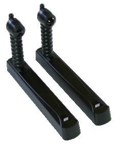
I      ISTRUZIONI DI SICUREZZA IMPORTANTI PER L’INSTALLAZIONE
                                                                                      F      INSTRUCTIONS DE SECURITE IMPORTANTES POUR
                                                                                             L’INSTALLATION

                           - ATTENZIONE -                                                                       - ATTENTION -
PER LA SICUREZZA DELLE PERSONE É IMPORTANTE CHE VENGANO SEGUITE                       POUR LA SECURITE DES PERSONNES IL EST IMPORTANT QUE TOUTES LES
TUTTE LE ISTRUZIONI                                                                   INSTRUCTIONS SOIENT SUIVIES

1° - Questo libretto d’istruzioni è rivolto esclusivamente a personale               1° - Ce livret d’instructions est adressé exclusivement à un personnel
      specializzato che sia a conoscenza dei criteri costruttivi e dei                      spécialisé qui connaît les critères de construction et les dispositifs
      dispositivi di protezione contro gli infortuni per i cancelli, le porte               de protection contre les accidents concernant les portails, les
      e i portoni motorizzati (attenersi alle norme e alle leggi vigenti).                  portes et les grandes portes motorisés (s’en tenir aux normes et
2° - L’installatore prima di procedere con l’installazione deve prevedere                  aux lois en vigueur).
      l’analisi dei rischi della chiusura automatizzata finale e la messa in          2° - L’installateur avant de procéder à l’installation, doit prévoir
      sicurezza dei punti pericolosi identificati (seguendo le norme EN                     l’analyse des risques de la fermeture automatisée finale et la mise
      12453).                                                                               en sécurité des points identifiés dangereux (en suivant les normes
3° - Prima di eseguire qualsiasi operazione di installazione, regolazione,                 EN 12453).
      manutenzione dell’impianto, togliere la tensione agendo                         3° - Avant l’exécution de toute opération d’installation, de réglage,
      sull’apposito interruttore magnetotermico collegato a monte dello                     d’entretien de l’installation, couper le courant en agissant sur
      stesso.                                                                               l’interrupteur magnétothermique à cet effet, branché en amont
                                                                                            de l’installation.
LA DITTA RIB NON ACCETTA NESSUNA RESPONSABILITÀ per eventuali
danni provocati dalla mancata osservanza nell’installazione delle                     LA SOCIETE RIB N’ACCEPTE AUCUNE RESPONSABILITE pour d’éventuels
norme di sicurezza e delle leggi attualmente in vigore.                               dommages provoqués par la non-observation dans l’installation, des
                                                                                      normes de sécurité et des lois actuellement en vigueur.

CONSERVARE CON CURA QUESTE ISTRUZIONI                                                 CONSERVER SOIGNEUSEMENT CES INSTRUCTIONS

I dati descritti nel presente manuale sono puramente indicativi.                      Les données figurant dans le présent manuel sont fournies à titre
RIB si riserva di modificarli in qualsiasi momento.                                   purement indicatif.
Realizzare l’impianto in ottemperanza alle norme ed alle leggi vigenti.               RIB se réserve le droit de les modifier à tout moment, sans aucun
                                                                                      préavis.
                                                                                      Effectuer l’installation en conformité avec les normes et les lois en
                                                                                      vigueur.

CURA E MANUTENZIONE                                                                   CONTROLES ET ENTRETIEN

Deve essere effettuata solo da personale autorizzato in accordo con                   Il doit être effectué seulement de personnel autorisé en accord avec
le regole di sicurezza e con le istruzioni del fabbricante, con frequenza             les règles de sûreté et avec les instructions du fabricant, avec la
semestrale.                                                                           fréquence semestrielle.
- I dispositivi di sicurezza devono essere mantenuti in condizioni di               - La dispositifs de sécurité doivent être maintenus en condition de
    lavoro efficienti e in accordo con le istruzioni del fabbricante.                    travail efficace en respectant les instructions du fabricant.
 - Verificare la presenza e la leggibilità della marcatura iniziale del              - Vérifier la présence et la lisibilité du marquageinitial du produit.
    prodotto.                                                                         - Substituer les batteries lorsque demandé du système (voir tableau
 - Sostituire le batterie quando richiesto dal sistema (vedere tabella “IN              EN CAS DE DIFFICULTÉ).
    CASO DI DIFFICOLTÀ”).                                                             - Nettoyer à l’aide d’un chiffon humide les lentilles sur l’émetteur et le
 - Pulire le lenti presenti sul trasmettitore e ricevitore, usando un panno             récepteur.
    umido.                                                                            - Vérifier l’intégrité des boîtiers et des soufflets. En cas de dommages,
 - Verificare l’integrità dei contenitori e dei soffietti. Se sono danneggiati          ces derniers devront être remplacés.
    devono essere sostituiti.                                                         - Vérifier l’élasticité des soufflets en les pliant et en constatant le
 - Verificare l’elasticità dei soffietti piegandoli e constatando che                   retour dans leur position initiale.
    ritornino nella posizione iniziale.

                                                                                  2
G
B
IMPORTANT SAFETY INSTRUCTIONS FOR THE INSTALLATION
D WICHTIGE SICHERHEITS
INSTALLATIONEN
ANLEITUNGEN FÜR DIE
- ATTENTION - - ACHTUNG -
FOR THE SAFETY OF THE PEOPLE IT IS IMPORTANT TO FOLLOW ALL THE FÜR DIE SICHERHEIT DER PERSONEN IST ES WICHTIG, DASS ALLE
INSTRUCTIONS. ANWEISUNGEN GENAU AUSGEFÜHRT WERDEN
1° - This handbook is exclusively addressed to the specialized 1° - Diese Betriebsanleitung dient ausschließlich dem Fachpersonal,
personnel who knows the constructive criteria and the protection welche die Konstruktionskriterien und die Sicherheits-Vorschriften
devices against the accidents for motorized gates, doors and main gegen Unfälle für Tore, Türen und automatische Tore kennt
doors (follow the standards and the laws in force). (geltende Normen und Gesetze beachten und befolgen).
2° - Before proceeding with the installation, the installer must forecast 2° - Vor der Installierung muss für die automatische Schließung und
the risks analysis of the final automatized closing and the safety zur Sicherheitsgewährung der identifizierten kritischen Punkte,
of the identified dangerous points (following the standards EN eine Risiko Analyse vorgenommen werden mit der entsprechenden
12453). Behebung der identifizierten, gefährlichen Punkte (die Normen EN
3° - Before carrying out any installation, regulation or maintenance 12453 befolgend).
operation of the system, take off the voltage by operating on the 3° - Vor jeglichem Eingriff, sei es Installation, Regulation oder Wartung
special magnetothermic switch connected upstream it. der Anlage, muss vorher die Stromzufuhr unterbrochen werden,
den dafür bestimmten Magnetthermo-Schalter drücken, der am
THE RIB COMPANY DOES NOT ACCEPT ANY RESPONSIBILITY for possible Eingang der Anlage installiert ist.
damages caused by the non observance during the installation of the
safety standards and of the laws in force at present. DIE FIRMA RIB ÜBERNIMMT KEINE VERANTWORTUNG für eventuelle
Schäden, die entstehen können, wenn die Installierungsvorschriften
die den gültigen Sicherheitsnormen entsprechen, nicht eingehalten
werden.
INSTALLATIONSVORSCHRIFTEN BEACHTET WERDEN
KEEP THESE INSTRUCTIONS WITH CARE
Die in diesem Handbuch aufgeführten Daten sind ausschließlich
Data described by this manual are only Indicative. empfohlene Werte. RIB behält sich das Recht vor, das Produkt zu jedem
RIB reserves to modify them at any time. Zeitpunkt zu modifizieren.
Install the system complying with current standards and regulations. Die Anlage muss in Übereinstimmung mit den gültigen Normen und
Gesetzen montiert werden.
PFLEGE UND WARTUNG
MAINTANANCE
Das darf nur von autorisiertem Personal, in Übereinstimmung mit
Must be carried out every six months, only by authorized personnel Sicherheits-Vorschriften und Anweisungen des Herstellers, alle sechs
in agreement with the safety rules and with the manufacturer’s Monate gemacht.
instructions. - Die Sicherheitsvorrichtungen müssen in einwandfreiem Zustand
- The safety accessories must be maintained in good and efficient gehalten und gemäß den Anweisungen des Herstellers verwaltet
conditions in accordance with the manufacturer’s instructions. werden.
- Verify the presence and readability of the original markings on the - Überprüfen Sie das Vorhandensein und die Lesbarkeit der ersten
product. Markierung des Produktes.
- Replace the batteries when requested by the system (see the chart - Wechseln Sie die Batterien, wenn das System fragt (siehe Tabelle “IM
“IN CASE OF DIFFICULTIES”). FALLE VON SCHWIERIGKEITEN”).
- Clean the lenses on the transmitter and the receiver using a wet cloth. - Reinigen Sie die Linsen auf Sender und Empfänger mit einem feuchten
- Check that the packaging containers and the bellows are intact. If Tuch.
they are damaged, they must be replaced. - Überprüfen Sie die Unversehrtheit der Gehäuse und Bälge. Falls sie
- Check the elasticity of the bellows by folding them and observing beschädigt sind, müssen sie ausgewechselt werden.
whether they return to their original position. - Prüfen Sie die Bälge auf ihre Biegsamkeit und stellen Sie sicher, dass
sie in ihre ursprüngliche Position zurückkehren.
3E IMPORTANTES INSTRUCCIONES DE SEGURIDAD PARA LA
S INSTALACIÓN
VERTIGO 8
- CUIDADO - 80
22
UNA INCORRECTA INSTALACIÓN PUEDE CAUSAR GRAVES DAÑOS
25,1
1° - Este manual de instrucciones está exclusivamente dirigido a
18
80
personal especializado que conozca los criterios de construcción y
de los dispositivos de protección contra accidentes con cancelas, 22
puertas y portales motorizados (atenerse a las normas y a las leyes
25,1
vigentes). 58
18
208,5
192,5
2° - El instalador antes de proceder con la instalación tiene que hacer
una analisis de los riesgos del cierre automatizado final y la
puesta en seguridad de los puntos identificados como peligrosos
(siguiendo las normas EN 12453). 58
208,5
192,5
16,5
3° - Antes de ejecutar cualquier operación de instalación, ajuste
o mantenimiento del sistema, quitar la corriente accionando
el respectivo interruptor magnetotérmico conectado antes del
mismo.
30 101 3
16,5
LA EMPRESA RIB NO ES RESPONSABLE por eventuales daños provocados
por la falta de respeto de las normas de seguridad, durante la 1
instalación y de las leyes actualmente vigentes. Misure in mm
30 Mesures en101
mm 3
24,5
Measurements in mm
Abmessungen in mm
Mesures en mm
1
CONSERVAR CUIDADOSAMENTE ESTAS INSTRUCCIONES
24,5
Los datos descritos en el presente manual son sólamente indicativos.
RIB se reserva de modificarlos en cualquier momento.
Realizar el sistema respetando las normas y las leyes vigentes. 100
VERTIGO
22 10
25,1
CUIDADO Y MANTENIMIENTO
18
100
Las operaciones de montaje sólo pueden ser efectuadas por personal 22
autorizado de conformidad con las normas de seguridad y con las
25,1
instrucciones del fabricante. Dichas operaciones deben realizarse cada 78
18
208,5
seis meses. 192,5
- Los dispositivos de seguridad deben mantenerse en buenas
condiciones de trabajo eficiente de acuerdo con las instrucciones del
fabricante. 78
- V erificar la presencia y la legibilidad del marcado inicial del producto.
16,5
208,5
192,5
- Sustituya las baterías cuando el sistema lo solicite (véase tabla “EN
CASO DE DIFICULTAD”).
- Limpiar las lentes situadas en el transmisor y el receptor utilizando
un paño húmedo. 30 121 3
16,5
- Verificar la integridad de los contenedores y los fuelles. En caso de
que estén dañados, deben ser reemplazados. 1
- Verificar la elasticidad de los fuelles doblándolos y comprobando que
estos vuelvan a su posición inicial. 30 121 3
24,5
1
Misure in mm
24,5
Mesures en mm
Measurements in mm
Abmessungen in mm
Mesures en mm
4I
VERTIGO è conforme alle norme EN12978 e EN13849-2 (2013) e congiuntamente ad un quadro
elettronico RIB è un dispositivo di protezione PL “c” Categoria 2 atto a garantire la protezione
di persone/cose da urti provocati da organi meccanici in movimento quali cancelli o porte a
chiusura automatica.
L’ostacolo viene rilevato su tutta la distanza presente tra i dispositivi trasmettitore e ricevitore
del raggio infrarosso che costituiscono il prodotto VERTIGO.
VERTIGO può essere posizionato in zone raggiungibili da cavi elettrici.
Utilizzando i quadri elettronici RIB è possibile eseguire l’autotest del sistema.
Utilizzare attuatori RIB, quadri elettronici RIB dotati di autotest e sicurezze RIB permette di
realizzare un’installazione conforme alle Norme e Direttive Europee in vigore.
Una volta ultimato l’impianto ci si deve sincerare che sia conforme alla norma EN13241-2016.
RIB non puó considerarsi responsabile per eventuali danni causati da un uso improprio, erroneo
RX
o irragionevole del prodotto.
RIFERIMENTI NORMATIVI PER PORTE E CANCELLI AUTOMATICI INSTALLAZIONE
RIB NON PUÓ CONSIDERARSI RESPONSABILE PER EVENTUALI DANNI CAUSATI DA UN USO IMPROPRIO, IMPORTANTE!
ERRONEO O IRRAGIONEVOLE. Se utilizzate un quadro elettronico NON RIB,
Restrizioni d’uso: Le fotocellule VERTIGO non possono essere utilizzate su apparecchiature questo deve essere conforme ai tempi di
escluse dall’applicazione della EN12978, quali: reazione (inversione) previsti dalla norma
- apparati di protezione per installazione su porte destinate ad un uso differente rispetto a EN 12453 (requisiti della sicurezza in uso di
quello sulle porte di accessi pedonali e veicolari coperti dalla norma e il cui principale uso è porte motorizzate).
quello di dare accesso sicuro in luoghi industriali, commerciali, pubblici o residenziali. Alcuni
esempi di esclusioni possono essere: chiuse e paratie; porte di ascensori; porte di veicoli; POSIZIONARE IL RICEVITORE DELLA
porte principalmente usate per la custodia di animali; tende in tessuto per teatro; barriere FOTOCELLULA ALL’ESTREMITÀ SUPERIORE
ferroviarie; barriere utilizzate solo per veicoli. DELLE COLONNE DEL CANCELLO.
- dispositivi usati solo per il controllo normale e per l’arresto, incluso l’arresto di emergenza, di
porte motorizzate. IL TRASMETTITORE VERTIGO DEVE ESSERE
- apparati di sicurezza o dispositivi di sicurezza per l’uso su macchine diverse dalle porte. APPLICATO ALL’ESTREMITÀ INFERIORE DELLE
ATTENZIONE: Eventuali modifiche del prodotto o della configurazione dell’apparato non COLONNE DEL CANCELLO.
possono essere eseguite senza consultare il fabbricante o il suo rappresentante
autorizzato.
L’installatore del dispositivo di sicurezza deve fornire all’utilizzatore finale quanto segue:
- i dispositivi di sicurezza devono essere fatti conoscere a tutte le persone coinvolte.
- le aree che danno accesso ai dispositivi devono essere tenute libere da ostacoli;
- le indicazioni per la pulizia per evitare accumuli di sporcizia;
- possibili dettagli per una procedura di riavvio da eseguire dopo una fermata di emergenza o
accidentale causata dal sistema di controllo.
La modifica del progetto o della configurazione dell’apparato senza la consultazione del
fabbricante o del suo rappresentante autorizzato può creare situazioni pericolose.
Le VERTIGO sono prodotte nelle versioni da parete:
- VERTIGO 8 cod. ACG8044
- VERTIGO 10 cod. ACG8045
da fissare su colonne (o pareti) in ferro o in altro materiale liscio.
È possibile se necessario, ruotare di 90° in 90° l’uscita del raggio infrarosso.
TX
CAMPO DI APPLICAZIONE
PESO MAX CANCELLO VELOCITÁ MAX SPOSTAMENTO
150 kg 13 m/min.
8
300 kg 10 m/min.
500 kg 13 m/min.
10
1000 kg 10 m/min.
5I TRASMETTITORE SEGNALE INFRAROSSO - TX
MONTAGGIO TRASMETTITORE SEGNALE INFRAROSSO SETTAGGI E
- Separare il coperchio con il supporto in gomma (1) dalla base (2) e sfilare la scheda COLLEGAMENTI TRASMETTITORE
elettronica (3) (Fig. 2).
- Rimuovere la palpebra tramite pressione con cacciavite e montare il passacavo in dotazione.
- Appoggiare la base (2) sul bordo inferiore dell’anta del cancello e fissarla tramite 2 viti
autofilettanti TCCR3,5X16 in dotazione (4). J2 Morsettiera per collegamento filare
- Verificare la presenza e l’integrità della guarnizione presente all’interno del coperchio (1). AD+TEST Alimentazione 12-24V ac/dc J2
- Se necessario ruotare di 90° il gruppo soffietto in modo da orientare il raggio d’uscita AD- Alimentazione 12-24V ac/dc
infrarosso come desiderato (VERTIGO viene fornita con raggio d’uscita come da Fig. 2).
E’ possibile orientare diversamente il raggio:
12
10
- Inserire la scheda elettronica (3) già identificata, collegata al suo coperchio con soffietto,
8
nelle apposite guide presenti sulla base (2).
TX
- Dando alimentazione, sul trasmettitore 9 il led verde DLTX (Fig. 1) si accende segnalando il
corretto funzionamento.
- Montare il coperchio (1) facendolo agganciare alla base (2) nella parte superiore tramite
apposito dente, e quindi chiudere il coperchio. 11
- Verificare, una volta chiuso il coperchio, che resti parallelo alla base. In caso contrario,
riaprirlo e verificare che il circuito e i fili di collegamento siano stati correttamente alloggiati.
- Fissare il coperchio (1) alla base (2) con le 4 viti autofilettanti TCCR2,9X9,5 in dotazione (5).
QUADRI ELETTRONICI RIB ABILITATI AL CONTROLLO ABILITARE LA FUNZIONE DI
AUTOTEST AUTOTEST TRAMITE
K-CRX
7 DIP 10 - ON DLTX
DLTX Led verde per verifica funzionamento
COLLEGARE IL MORSETTO
L1-CRX A/D+ TEST DIP 7 - ON
AL MORSETTO J1 Connettore per diodo trasmettitore J1
B2-CRX DIP 7 - ON
A+ TEST
B2 24V-CRX DIP 7 - ON 1
1
2
5
3
TX
4
6
2 3
6RICEVITORE SEGNALE INFRAROSSO - RX
I
- Separare il coperchio con il supporto in gomma dalla base e sfilare la scheda elettronica SETTAGGI E COLLEGAMENTI
(Fig. 5). RICEVITORE J3
- Rimuovere la palpebra tramite pressione con cacciavite e montare il passacavo in dotazione.
- Appoggiare la base sul bordo superiore della colonna del cancello (ad una distanza massima J3 Connettore per diodo ricevitore
di 3 metri dal trasmettitore). DLRX
- Fissarla tramite 2 viti autofilettanti TCCR3,5X16 in dotazione . DLRX Led rosso per segnalare la corretta
- Verificare la presenza e l’integrità della guarnizione presente all’interno del coperchio .
alimentazione e l’allineamento del
- Se necessario ruotare di 90° il gruppo soffietto in modo da orientare il raggio d’uscita
segnale infrarosso
infrarosso come desiderato (VERTIGO viene fornita con raggio d’uscita come da Fig. 5).
È possibile orientare diversamente il raggio:
- Inserire la scheda elettronica già identificata, collegata al suo coperchio con soffietto, nelle
apposite guide presenti sulla base.
RX
- Dando alimentazione, sul ricevitore il led rosso DLRX (Fig. 4) si accende segnalando il corretto
funzionamento.
ATTENZIONE: Se il led del ricevitore rimane acceso, o lampeggia durante il funzionamento, è
possibile che siano presenti dei disturbi sulla rete di alimentazione.
Vi consigliamo di collegare elettricamente a terra il morsetto AD- per proteggere le fotocellule
da fonti di disturbo.
Fate attenzione a non creare corto circuiti quando le fasi di alimentazione sono invertite!
J4 Morsettiera per collegamento filare
AD+ alimentazione 12-24V ac/dc
AD- alimentazione 12-24V ac/dc
COM Comune dei contatti
J4
EDGE Contatto normalmente chiuso NC
4
12
10
8
9
RX
11
7
1
5 6
7I RICEVITORE SEGNALE INFRAROSSO - RX
VERIFICA DEL CORRETTO FUNZIONAMENTO CARATTERISTICHE TECNICHE
Terminata la procedura di montaggio, verificare il corretto funzionamento nel seguente modo:
- Verificare che sul ricevitore infrarosso RX VERTIGO il led rosso sia acceso, in caso contrario RICEVITORE VERTIGO
orientare ricevitore e trasmettitore in modo che siano allineati tra loro. - ALIMENTAZIONE 1 2÷24 V ac/dc
- Verificare che interponendo un ostacolo il led rosso si spenga e che - ASSORBIMENTO MASSIMO 30 mA
contemporaneamente sulla cenralina il corrispondente led EDGE si spenga per la durata - TEMPERATURA DI LAVORO -20°C ÷ +60°C
dell’interposizione. - COPERCHIO in policarbonato
- Ripetere la verifica sulle altre fotocellule VERTIGO installate. - BASE in ABS
- Eseguire poi una verifica funzionale di tutte le VERTIGO installate attivando il cancello e - SOFFIETTO in silicone
controllando che interponendo un ostacolo l’automazione si fermi/inverta se in chiusura, - GRADO DI PROTEZIONE IP55
oppure si fermi/continui ad aprire se in apertura. - PESO 0,135 kg
TRASMETTITORE VERTIGO
- ALIMENTAZIONE 12÷24 V ac/dc
CHIUSURA CONTENITORI VERTIGO - ASSORBIMENTO 20mA
Applicare infine sia sul TX che sull’RX della VERTIGO i coperchi copriviti (6) (12) (Fig. 2-5) - TEMPERATURA DI LAVORO -20°C ÷ +60°C
inserendoli sui 4 fori di incastro in modo che aderiscano perfettamente. - COPERCHIO in policarbonato
- BASE in ABS
- SOFFIETTO in silicone
- GRADO DI PROTEZIONE IP55
- PESO 0,130 kg
DATI TECNICI SEGNALE INFRAROSSO TX
- PORTATA 3m
- LUNGHEZZA D’ONDA 850 nm
- DIMENSIONI DELLA ZONA DI RILEVAMENTO diametro 20 mm
IN CASO DI DIFFICOLTÁ
SINTOMO VERIFICA
Il led verde DLTX del trasmettitore non si accende fornendo alimentazione. Verificare presenza 12÷24 V ac/dc ai morsetti del trasmettitore.
Il led rosso DLRX del ricevitore non si accende fornendo alimentazione. Verificare presenza 12÷24 V ac/dc ai morsetti del ricevitore e allineamento raggio infrarosso tra
trasmettitore e ricevitore.
Il cancello non si apre. VERTIGO non allineata, o impegnata (led rosso su RX spento). Eseguire una verifica di
allineamento fino ad accendere il led rosso.
Il cancello non si chiude Autotest fallito (se abilitato).
VERTIGO non allineata o impegnata (led rosso su RX spento). Eseguire una verifica di allineamento
fino ad accendere il led rosso
8F
VERTIGO est conforme à la norme EN12978 et EN13849-2 (2013) s’il est conjointement utilisé
avec un tableau électrique de la marque RIB, constitue un dispositif de protection PL “c”
de Catégorie 2. Son but est de protéger les personnes/objets d’un quelconque choc qui
proviendrait d’appareils mécaniques en mouvement comme des portails ou des portes à
fermeture automatique.
Le système repère l’obstacle au niveau de la distance existante entre les dispositifs d’émission
et de réception du rayon infrarouge, lesquels constituent le produit VERTIGO.
VERTIGO peuvent être positionnées avec l’utilisation de fils électriques.
L’utilisation d’actionneurs RIB, de tableaux électriques RIB dotés de test automatique et
de sécurités RIB permet de réaliser une installation conforme aux normes et directives
européennes en vigueur.
Une fois l’installation terminée, il faut s’assurer qu’elle soit conforme à la norme EN13241-2016.
RX
RIB ne peut être tenu responsable d’éventuels dommages résultant d’une utilisation impropre,
inadéquate ou irresponsable du produit.
INSTALLATION
RÉFÉRENCES NORMATIVES POUR PORTES ET PORTAILS AUTOMATISÉS
IMPORTANT!
RIB SE DÉCHARGE DE TOUTE RESPONSABILITÉ DES DOMMAGES CAUSÉS PAR UNE UTILISATION NON Assurez-vous que si vous utilisez un
CONFORME, ERRONÉE OU DÉRAISONNÉE panneau de commande PAS RIB, ce doit être
Restrictions de mode d’emploie: Les photocellules VERTIGO ne peuvent pas être utilisées sur en conformité avec les temps de réaction
des appareillages exclus de l’application de l’EN12978, quels: (inverse) fournies par la norme 12453
- appareils de protection pour installation sur des portes destinées à emploie différent par (exigences de sécurité dans l’utilisation de
rapport à cela sur les portes d’accès pour piétons et de véhicules couverts de la règle et portes motorisées).
le principal emploie est cela de donner accès sûr en lieux industriels, commerciaux, publics
ou résidentiels. Quelques exemples d’exclusions peuvent être: écluses et cloisons; portes POSITIONNER LA RECEPTEUR VERTIGO A
d’ascenseurs; portes de véhicules; des portes principalement employées pour la garde L’EXTREMITE SUPERIEURE DES COLONNES DU
d’animaux; draperies en tissu pour théatre; barrières ferroviaires; des barrières utilisées PORTAIL
seulement pour véhicules.
- dispositifs employés seulement pour contrôle normal et pour arrête, inclus arrête LE TRANSMETTEUR VERTIGO DOIT ETRE
d’émergence, de portes motorisées. PLACE A L’EXTREMITE INFERIEURE DES
- appareils de sûreté ou dispositifs de sûreté pour emploie sur des machines différentes des COLONNES DU PORTAIL.
portes.
ATTENTION: Des eventuelles modifications de produit ou de la configuration de l’appareil ne
peuvent pas être exécutées sans consulter le fabricant ou son représentant
autorisé.
L’installateur du dispositif de sûreté doit fournir à l’utilisateur final tout ce qui suit:
- les dispositifs de sûreté doivent être connus de toutes les personnes appropriées;
- les aires qui donnent accès aux dispositifs doivent être tenues libres d’obstacles;
- les qualités pour le nottoyage à éviter eventuelles accumulations dangereuses de matériel;
- possibles spécifications pour une procédure de renvoi à exécuter après une arrêtée
d’émergence ou accidentelle causée du système de contrôle.
La modification du projet ou de la configuration de l’appareil sans la consultation du fabricant
ou de son représentant autorisé peut créer des situations dangereuses.
VERTIGO sont disponibles dans les versions murales:
- VERTIGO 8
- VERTIGO 10
code ACG8044
code ACG8045
TX
Elles peuvent être fixées sur les bords primaires et/ou secondaires (mobiles ou fixes) en fer ou
avec un autre matériau lisse.
Vous pouvez, si nécessaire, tourner de 90° à 90° de la sortie du faisceau infrarouge :
CHAMP D’APPLICATION
POIDS MAX. PORTAIL VITESSE MAX. DEPLACEMENT
150 kg 13 m/min.
8
300 kg 10 m/min.
500 kg 13 m/min.
10
1000 kg 10 m/min.
9F EMETTEUR SIGNAL INFRAROUGE - TX
MONTAGE EMETTEUR SIGNAL INFRAROUGE RÉGLAGES ET CONNEXIONS DE
- Ôter le couvert avec le support en caoutchouc (1) de la base (2) et enlever la carte L’ÉMETTEUR
électronique (3) (Fig. 2).
- Enlever le morceau en plastique qui couvre le trou où les câbles passent par tournevis et
monter le passe câble J2 Bornes pour raccordement filaire
- Positionner la base (2) sur le bord inférieur du vantail du portail et la fixer au moyen de 2 vis AD+TEST Bornes d’alimentation 12-24V ac/dc J2
autotaraudeuses TCCR3,5X16, fournies (4). AD- Bornes d’alimentation 12-24V ac/dc
- Vérifier la présence et l’intégrité de la garniture interne du couvert (1).
- Si nécessaire, tourner de 90° l’ensemble soufflet afin de diriger le faisceau de sortie
infrarouge comme vous le souhaitez (VERTIGO est fourni avec le faisceau de sortie comme
le montre la Fig. 2).
Vous pouvez changer l’orientation du faisceau:
12
8
10
- Insérer la carte électronique (3) au couvert avec soufflet, sur les guidages prévus à cet effet
TX
sur la base (2).
9
- En donnant l’alimentation, sur le transmetteur la led verte DLTX (Fig. 1) s’allume et signale le
fonctionnement correct.
- Installer le couvert (1) en l’accrochant à la base (2) dans la partie supérieure, grâce aux dents
prévues à cet effet, puis fermer le couvert. 11
- Une fois le couvert fermé, assurez-vous qu’il soit parallèle à la base. Si tel n’est pas le cas, le
réouvrir et vérifier que le circuit et les câbles de connexion ont été correctement positionnés.
- Fixer le couvert (1) sur la base (2) au moyen des 4 vis autotaraudeuses TCCR2,9X9,5 fournies
(5).
TABLEAUX ELECTRONIQUES RIB HABILITES AU CONTROLE HABILITER LA FONCTION
AUTOTEST D’AUTOTEST PAR
K-CRX 7 DIP 10 - ON DLTX LED verte pour vérifier le DLTX
RELIER LA BORNE fonctionnement
L1-CRX A/D+ TEST DIP 7 - ON
A LA BORNE J1
B2-CRX DIP 7 - ON J1 Connecteur pour diode émetteur
A+ TEST
B2 24V-CRX DIP 7 - ON 1
1
2
5
3
TX
4
6
2 3
10RECEPTEUR SIGNAL INFRAROUGE - RX
F
MONTAGE RÉCEPTEUR SIGNAL INFRAROUGE RÉGLAGES ET CONNEXIONS DU
J3
- Ôter le couvert avec le support en caoutchouc (7) de la base (8) et enlever la carte RÉCEPTEUR
électronique (9) (Fig. 5).
- Enlever le morceau en plastique qui couvre le trou où les câbles passent par tournevis et J3
Connecteur pour diode récepteur DLRX
monter le passe câble
- Poser la base (8) sur le bord supérieur du vantail du portail (à une distance maximale de 3 DLRX LED rouge pour signaler l’alimentation
mètres de l’émetteur). correcte et l’alignement du signal
- La fixer au moyen de 2 vis autotaraudeuses TCCR3,5X16, fournies (10). infrarouge
- Vérifier la présence et l’intégrité de la garniture interne du couvert (7).
- Si nécessaire, tourner de 90° l’ensemble soufflet afin de diriger le faisceau de sortie
infrarouge comme vous le souhaitez (VERTIGO est fourni avec le faisceau de sortie comme
le montre la Fig. 5).
Vous pouvez changer l’orientation du faisceau:
RX
- Insérer la carte électronique déjà identifiée et reliée au couvert avec soufflet, sur les
guidages prévus à cet effet sur la base.
- En donnant l’alimentation, sur le récepteur une led rouge DLRX (Fig. 4) reste allumée
indiquant le bon fonctionnement du dispositif.
ATTENTION: Si la led du récepteur reste allumée ou clignote pendant le fonctionnement, il est
possible qu’ il y ait des perturbations sur la ligne d’alimentation.
Nous conseillons de relier électriquement à terre la borne AD- pour protéger les photocellules
de sources de dérangement.
Faire attention de ne pas provoquer de court-circuit quand les phases d’alimentation sont J4 Bornes pour raccordement filaire
inversées ! AD+TEST B ornes d’alimentation 12-24V ac/dc
AD- Bornes d’alimentation 12-24V ac/dc J4
COM Commun des contacts
EDGE Contact normalement fermé NC
4
12
10
8
9
RX
11
7
1
5 6
11F
CONTRÔLE DU FONCTIONNEMENT CARACTÉRISTIQUES TECHNIQUES
Une fois la procédure de montage terminée, contrôler le fonctionnement entre les photocellules
VERTIGO et le coffret electronique de la manière suivante: RÉCEPTEUR VERTIGO
- Vérifier que la led rouge du récepteur infrarouge RX VERTIGO est allumée. Si tel n’est pas le - ALIMENTATION 12÷24 V ac/dc
cas, aligner l’émetteur et le récepteur pour activer la led rouge. - CONSOMMATION MAX 30 mA
- Contrôler qu’en interposant un obstacle la LED rouge s’éteigne et qu’en même temps la LED - TEMPÉRATURE DE TRAVAIL -20°C ÷ +60°C
rouge correspondante EDGE présente sur le coffret electronique s’éteigne pendant la durée - EXTÉRIEUR en polycarbonate
de l’interposition. - BASE en ABS
- Répéter le contrôle sur les autres photocellules VERTIGO installées. - SOUFFLET en silicone
- Effectuer ensuite un contrôle de fonctionnement de toutes les VERTIGO installées en activant - DEGRÉ DE PROTECTION IP55
le mouvement de l’automatisme et en contrôlant que l’interposition d’un obstacle arrête/ - POIDS 0,135 kg
inverse (si automatisme en fermeture) le mouvement, ou qu’elle arrête/continue à ouvrir (si
automatisme en ouverture). ÉMETTEUR VERTIGO
- ALIMENTATION 12÷24 V ac/dc
- ABSORPTION 20 mA
- TEMPÉRATURE DE TRAVAIL -20°C ÷ +60°C
FERMETURE DES BOITIERS VERTIGO - EXTÉRIEUR en polycarbonate
- BASE en ABS
Installer, enfin, sur l’émetteur et le récepteur de la photocellule VERTIGO les capuchons cache-
- SOUFFLET en silicone
vis (6) (12) (Fig. 2-5) en les insérant dans les 4 trous prévus à cet effet, pour qu’ils adhèrent
- DEGRÉ DE PROTECTION IP55
parfaitement.
- POIDS 0,130 kg
DONNÉES TECHNIQUES FAISCEAU INFRAROUGE
- PORTÉE 3m
- LONGUEUR D’ONDE 850 nm
- DIMENSIONS DE LA ZONE DE RELEVÉ diamètre 20 mm
EN CAS DE DIFFICULTÉ
SYMPTOME CONTRÔLE
La LED verte DLTX de l’émetteur ne s’allume pas après avoir fourni l’alimentation. - Vérifier l’alimentation 12÷24 V ac/dc au terminal de l’émetteur.
La LED rouge DLRX du récepteur ne s’allume pas après avoir fourni l’alimentation. - Vérifier l’alimentation 12÷24 V ac/dc au terminal du récepteur et l’allignment de l’émetteur
avec le récepteur
Le portail ne s’ouvre pas. - VERTIGO non alignée, occupée (led rouge su le recepteur éteint). Verifier l’allignment de
l’émetteur avec le récepteur
Le portail ne se ferme pas - AUTOTEST manqué.
- VERTIGO non alignée, occupée (led rouge su le recepteur éteint). Verifier l’allignment de
l’émetteur avec le récepteur
12G
B
VERTIGO conforms to standards EN12978 and EN13849-2 (2013) when used with a RIB electronic
control panel it is a PL “c” Category 2 protection device for protecting persons/things from
collisions caused by mechanical moving parts such as automatic gates or doors.
The obstacle is detected for the whole distance between the infrared transmitter and receiver
which constitute the VERTIGO product.
When using RIB electronic control panels you can run auto-tests on the system.
With RIB actuators, RIB electronic control panels having the auto-test function and RIB safety
devices you can create an installation that conforms to the European Directives and Norms in
RX
force.
After completing the system, you must make sure it conforms to standard EN13241-2016.
RIB shall not be liable for any damages caused by improper, incorrect or unreasonable use of
the product.
VERTIGO photocells cannot be used on devices excluded by the application of the EN12978,
such as: MOUNTING
- Protection devices for the installation on doors used for a different purpose to those ones
used for pedestrian or veheicle access, covered by the norm which principal intent is that of VERY IMPORTANT!
allowing a safe access to industrial, commercial, public and commercial sites. Some examples Verify that when using a NOT RIB control
of excluded accesses can be: sluice gates, dams, lift doors, vehicles’ doors, doors used mainly panel, this one must be complying with
to restrain animals, theatre curtains, railways barriers, barriers used only for vehicles. the reaction time (inversion) requested by
- Devices used only fo the standard control and for the stopping, including the emergency the Norm EN 12453 (requirements of safety
stopping, of motorized doors. devices used on motorized gates/doors).
- Safety systems and safety devices used on machineries different from doors.
Any possible modification of the device, or of the configuration of the same cannot be carried PLACE THE RECEIVER OF THE PHOTOCELL ON
out without the clear authorization by the manufacturer or, by the local authorized dealer. THE TOP OF THE COLUMNS OF THE GATE.
The installer of the safety device must make sure that the end user know the following:
- That the safety devices must be made known to all appropriate people. THE VERTIGO TRANSMITTER MUST BE
- That the passages to reach the devices must be kept clear from any obtsacle. APPLIED TO THE BOTTOM OF THE COLUMNS
- About the procedures for cleaning so to avoid the dangerous building up of material. OF THE GATE.
- The possible details for a restart of the system after an emergency or accidental stop caused
by the control system.
Any modification of the project or, of the configuration of the device, without discussing it
first with the manufacturer or with the local autorized dealer can cause dangerous situations.
VERTIGO are produced in wall-type versions:
code ACG8044
code ACG8045
to be fasten to the primary and/or secondary borders (mobile or fixed) made of iron or other
smooth material.
- VERTIGO comes with the infrared ray set as per Fig. 6.
It is possible to direct the infrared ray according to the needs:
TX
APPLICATION
MAX GATE WEIGHT MAX DISPLACEMENT SPEED
150 kg 13 m/min.
VERTIGO 8
300 kg 10 m/min.
500 kg 13 m/min.
VERTIGO 10
1000 kg 10 m/min.
13G
B INFRARED SIGNAL TRANSMITTER - TX
ASSEMBLY OF THE INFRARED TRANSMITTER TRANSMITTER
- Separate the cover with the rubber support (1) from the base (2) and remove the electronic SETTINGS AND CONNECTIONS
board (3) (Fig. 2).
- Remove the lid doing pressure with a screwdriver and insert the conduit supplied.
- Place the base (2) on the lower border of the leaf of the gate and fasten it immediately using J2 Terminal block
2 self-tapping screws TCCR3,5X16 supplied (4). AD+TEST Power Supply 12-24V ac/dc
- Check that the gasket is present and it is intact within the cover (1). AD- Power Supply12-24V ac/dc J2
- If necessary, rotate the bellows assembly which includes the lens by 90°, so to direct the
infrared ray as per need (VERTIGO comes with the infrared ray set as per Fig. 2). It is possible
to direct the ray according to the needs:
12
- Insert the electronic board (3), linked to the cover with the bellow, in the special rails on
the base (2).
8
10
- As power supply has been given to the transmitter, the DLTX green led (Fig. 1) turns ON
TX
indicating the proper functioning.
- Assemble the cover (1) attaching it9to the base (2) on the top part using the special tooth
and then close the cover.
- Once the cover is closed, check that it is parallel to the base. Otherwise, open it again and
check that the circuit and the connection wires are correctly fitted in their seats.
11 TCCR2,9X9,5 supplied (5).
- Fasten the cover (1) to the base (2) with the 4 self-tapping screws
SELF-TEST-ENABLED RIB CONTROL BOARDS ENABLE SELF-TEST FUNCTION
THROUGH
K-CRX DIP 10 - ON
CONNECT
A/D+ TEST DLTX
Green LED function indicator
L1-CRX DIP 7 - ON
TERMINAL TO 7 DLTX
B2-CRX A+ TEST DIP 7 - ON J1 Connector for the transmitter diode
TERMINAL
B2 24V-CRX DIP 7 - ON J1
1
1
2
5
3
TX
4
6 2 3
14G
INFRARED SIGNAL RECEIVER - RX B
ASSEMBLY OF THE INFRARED RECEIVER RECEIVER
- Separate the cover with the rubber support (7) from the base (8) and remove the electronic SETTINGS AND CONNECTIONS J3
board (9) (Fig. 5).
- Remove the lid doing pressure with a screwdriver and insert the conduit supplied. J3 Connector for the receiver diode
- Place the base (8) on the upper border of the leaf of the gate (at a maximum distance of 3 DLRX
metres from the transmitter). DLRX R ed LED indicating correct power and
- Fasten it immediately using 2 self-tapping screws TCCR3,5X16 supplied (10). infrared signal alignment
- Check that the gasket is present and it is intact within the cover (7).
- If necessary, rotate the bellows assembly which includes the lens by 90°, so to direct the
infrared ray as per need (VERTIGO comes with the infrared ray set as per Fig. 5). It is possible
to direct the ray according to the needs:
- Insert the electronic board already mentioned, linked to the cover with the bellow, in the
special rails on the base.
RX
- As power supply has been given to the receiver the DLRX red led (Fig. 4) lights on indicating
the proper functioning.
ATTENTION: In case the receiver led remains lit or blinks during gate movement, disturbs
inside the main supply are possible.
It is advisable to connect electrically to earth the terminal AD-, to shield the photocells from
these disturbs.
Be careful not to short circuit the system when the supply phases are inverted!
J4 Terminal block
AD+ Power Supply 12-24V ac/dc
AD- Power Supply 12-24V ac/dc J4
COM Contacts’ common
EDGE Normally closed contact NC
4
12
10
8
9 RX
11
7
1
5 6
15G
B INFRARED SIGNAL RECEIVER - RX
SYSTEM CHECK TECHNICAL SPECIFICATIONS
After finishing the mounting procedure, check the correct working by doing the following:
- Check on the infrared receiver RX VERTIGO that the red led is on. If it is not so, align VERTIGO RECEIVER
transmitter and receiver to turn the red led on. - POWER 12÷24 V ac/dc
- Place an object between them and check that the red LED turns OFF and that at the same - MAXIMUM ABSORPTION 25 mA
time on the control panel the corresponding LED EDGE is OFF and a while the object is present. - OPERATING TEMPERATURE -20°C ÷ +60°C
- Repeat the process on the other VERTIGO photocells installed. - COVER in polycarbonate
- Then perform a system check of all the photocells installed by activating the movement of - BASE in ABS
the automation and checking that when an object is present the automation stops/reverses - BELLOW in silicon
when closing, or stops/continues to open when opening. - PROTECTION LEVEL IP55
- WEIGHT 0,135 kg
VERTIGO TRANSMITTER
CLOSING THE VERTIGO CONTAINERS - POWER 12÷24 V ac/dc
Lastly, place the screw cover caps (6) (12) both on the TX and on the RX of the VERTIGO (Fig. - POWER ABSORBED 20 mA
2-5), by inserting them into the 4 holes so that they are perfectly attached. - OPERATING TEMPERATURE -20°C ÷ +60°C
- COVER in polycarbonate
- BASE in ABS
- BELLOW in silicon
- PROTECTION LEVEL IP55
- WEIGHT 0,130 kg
TX INFRARED SIGNAL TECHNICAL DETAILS
- RANGE 3m
- WAVELENGTH 850 nm
- DIMENSION OF THE DETECTION AREA diametre 20 mm
TROUBLESHOOTING
PROBLEM CHECK
The green LED DLTX of the TX does not turns on as you give power supply. - Check that on transmitter terminals is present the power supply 12÷24 V ac/dc
The red LED DLRX of the RX does not turns on as you give power supply. - Check that on TX and RX terminals is present the power supply 12÷24 V ac/dc and the correct
allignment between them
The gate does not open. VERTIGO is not aligned or stuck (red led on RX turned OFF). Check alignment between TX and RX
up to obtain red led turned on on RX.
The gate does not close. AUTOTEST failed.
VERTIGO is not aligned or stuck (red led on RX turned OFF). Check alignment between TX and RX
up to obtain red led turned on on RX.
16D
VERTIGO bei Benutzung mit der elektronischen Schalttafel von RIB wird es zu einem Gerät der
Schutz PL “c” Kategorie 2 zum Schutz von Personen/Gegenständen, mit denen bewegende Teile
von automatischen Toren oder Türen kollidieren können.
Das Hindernis wird auf der gesamten Distanz zwischen den Empfangs- und den
Sendevorrichtungen des Infrarotstrahls, aus denen sich das Produkt VERTIGO zusammensetzt,
erfasst.
Mit der elektronischen Schalttafel von RIB können Sie automatische Systemtests durchführen.
Bei RIB-Antrieben verfügen die elektronischen Schalttafeln von RIB über die Funktion zur
RX
Durchführung automatischer Systemtests und mit RIB-Sicherheitsgeräten können Sie die
Installation gemäß geltenden Europäischen Richtlinien und Normen ausführen.
Nach der Installation des Systems müssen Sie sicherstellen, dass es die Norm EN 13241-1 erfüllt.
RIB haftet nicht für Schäden jeglicher Art, die sich auf unsachgemäße, falsche oder
unangemessene Verwendung der Produkte zurückführen lassen.
HINWEIS AUF NORMEN FÜR AUTOMATISCHE TORE UND TÜREN MONTAGE
RIB KANN NICHT FÜR SCHÄDEN; DIE SICH AUF UNSACHGEMÄSSE, FALSCHE ODER UNANGEMESSENE
BENUTZUNG ZURÜCKFÜHREN LASSEN, HAFTBAR GEMACHT WERDEN. WARNUNG!
Gebrauchseinschränkungen: Die Fotozellen VERTIGO können sich nicht auf Geräte aus der Dass wenn Sie eine Steuerung NICHT RIB
EN12978, einschließlich ausgeschlossen werden: verwenden, die Steuerung muss im Einklang
- Schutzausrüstungen für den Einbau in Türen für einen anderen Zweck als der Fußgänger-und mit der Reaktionszeit (Inversion) in der
Fahrzeugverkehr Zugangstüren von der Regel abgedeckt sind und deren Hauptzweck ist Norm EN 12453 (Sicherheitsanforderungen
es, einen sicheren Zugang zu Stellen für Industrie-, Handels-, Wohn-oder öffentliche. Einige bei der Verwendung von kraftbetätigten
Beispiele für Ausschlüsse werden kann: Dämme und Schotten, Aufzugtüren, Fahrzeug-Türen, Türen).
verwendete Türen in erster Linie für die Lagerung von Tiere, Gewebe für Theater-Vorhänge,
Leitschienen, verwendete Schranken nur für Fahrzeuge. BRINGEN SIE DEN EMPFÄNGER DER FOTOZELLE
- Geräte, die nur für die normale Steuerung und Abschaltung, einschließlich der Not der Macht AM OBEREN RAND DER PFEILER DES TORS.
von Motortüren.
- Sicherheits-Ausrüstungen oder Sicherheitseinrichtungen für den Einsatz auf anderen DER EMPFÄNGER VERTIGO IST AM UNTEREN
Maschinerien, die Türen nicht sind. ENDE DER PFEILER DES TORS.
VORSICHT: Man kann nicht Änderungen am Produkt oder Gerät-Konfiguration ohne Rücksprache
mit dem Hersteller oder seinem Bevollmächtigten erfolgen.
Der Installer der Sicherheitseinrichtung muss dem Endbenutzer liefern, wie folgt:
- Sicherheitseinrichtungen müssen bekannt gemacht, alle geeigneten Personen sein.
- Gebiete, die den Zugang zu Geräten sollten frei von Hindernissen gehalten werden;
- Anforderungen an die Reinigung keine Ansammlung von gefährlichen Stoffen zu verhindern;
- Mögliche Einzelheiten für einen Wiederaufnahme-Verfahren nach einem Stopp in einem Notfall
oder Unfall durch das Steuersystem verursacht ausgeführt werden.
Ändern Sie das Design oder die Konfiguration der Geräte ohne Rücksprache mit dem Hersteller
oder sein Bevollmächtigter können zu gefährlichen Situationen führen.
VERTIGO werden in verschiedenen Wandversion hergestellt:
- VERTIGO 8 Kode ACG8044
- VERTIGO 10 Kode ACG8045
an den primären und/oder sekundären Rändern (beweglich oder fix) aus Eisen oder aus einem
anderen glatten Material zu befestigen.
Sie können, falls erforderlich, um 90° bis 90° den Ausgang des Infrarot-Strahl von der
TX
gesamten Schaltung des Behälters (siehe Abbildung).
ANWENDUNGSBEREICH
MAX. BEWEGUNG
MAX. GEWICHT TOR
GESCHWINDG-KEIT
150 kg 13 m/min.
8
300 kg 10 m/min.
500 kg 13 m/min.
10
1000 kg 10 m/min.
17D INFRAROTSIGNAL-SENDER - TX
MONTAGE DES INFRAROTSIGNAL-SENDERS EINSTELLUNGEN UND
- Nehmen Sie die Abdeckung mit der Gummihalterung (1) von der Basis (2) ab und führen Sie SENDERANSCHLÜSSE
die elektronische Karte (3) ein (Abb. 2).
- Mit einem Schraubendreher, drücken Sie die Kunststoffabdeckung das Loch von
Kabeldurchführung und montieren die Kabeldurchgang geliefert. J2 Klemmleiste zur Verbindung der Kabel
- Führen Sie die Basis (2) zum unteren Rand des Torflügels und befestigen Sie sie mit Hilfe der AD + TEST Versorgungsklemme 12-24V ac/dc J2
mitgelieferten 2 Gewinde-Schneidschrauben TCCR3,5X16 (4). AD- Versorgungsklemme 12-24V ac/dc
- Überprüfen Sie die Unversehrtheit der Dichtung im Inneren der Abdeckung (1).
- Falls erforderlich, können um 90° die Balgbaugruppe drehen, um den Strahl von Infrarot-
Licht, wie gewünscht (VERTIGO mit dem Ausgang Strahl geliefert, wie in Abb. 2 gezeigt) zu
leiten.
Sie können den Strahl lenken anders:
12
8
10
- Führen Sie die elektronische Karte (3), die über einen Balg mit ihrer Abdeckung verbunden
TX
ist, in die entsprechenden, an der Basis (2) vorgesehenen Führungen ein.
- Beim Einlegen der Batterien leuchtet9 10 Sekunden lang auf dem Sender die grüne LED DLTX
(Abb. 1) auf, um den korrekten Betrieb anzuzeigen.
- Bringen Sie die Abdeckung (1) an, indem Sie sie an der Basis (2) mit Hilfe des entsprechenden
Stifts im oberen Bereich befestigen. Schließen Sie dann die Abdeckung.
11
- Überprüfen Sie nach dem Schließen der Abdeckung, dass sie parallel zur Basis liegt.
Öffnen Sie sie andernfalls erneut und stellen Sie sicher, dass der Stromkreis und die
Verbindungsleitungen korrekt untergebracht sind.
- Befestigen Sie die Abdeckung (1) mit Hilfe der mitgelieferten 4 Gewinde-Schneidschrauben
TCCR2,9X9,5 (5) an der Basis (2).
AUTOTEST-KONTROLLE ZUGELASSENEN RIB-STEUERUNGEN FREIGABE DER AUTOTEST-
FUNKTION MITTELS
7 DLTX
Grüne LED-Funktionsanzeige DLTX
K-CRX DIP 10 - ON J1 Steckverbinder für die
DIE KLEMME Diodenverbindung des Senders
L1-CRX A/D+ TEST DIP 7 - ON J1
AN DIE KLEMME
B2-CRX A+ TEST DIP 7 - ON 1
ANSCHLIEßEN
B2 24V-CRX DIP 7 - ON
1
2
5
3
TX
4
6 2 3
18INFRAROTSIGNAL-EMPFÄNGER - RX
D
MONTAGE DES INFRAROTSIGNAL- EMPFÄNGER EINSTELLUNGEN UND EMPFÄNGER-
J3
- Nehmen Sie die Abdeckung mit der Gummihalterung (7) von der Basis (8) ab und führen Sie ANSCHLÜSSE
die elektronische Karte (9) ein (Abb. 5).
- Mit einem Schraubendreher, drücken Sie die Kunststoffabdeckung das Loch von J3 Steckverbinder für die Diodenverbindung DLRX
Kabeldurchführung und montieren die Kabeldurchgang geliefert. Empfänger
- Führen Sie die Basis (8) an den oberen Rand des Torpfeilers (in einer maximalen Entfernung
von 3 Metern vom Sender). DLRX R ote LED zeigt richtige Spannung und
- Befestigen Sie sie mit Hilfe der mitgelieferten 2 Gewinde-Schneidschrauben TCCR3,5X16 (10). Infrarotsignal-ausrichtung an
- Überprüfen Sie die Unversehrtheit der Dichtung im Inneren der Abdeckung (7).
- Falls erforderlich, können um 90° die Balgbaugruppe drehen, um den Strahl von Infrarot-
Licht, wie gewünscht (VERTIGO mit dem Ausgang Strahl geliefert, wie in Abb. 5 gezeigt) zu
leiten.
Sie können den Strahl lenken anders:
RX
- Führen Sie die bereits erkannte elektronische Karte, die über einen Balg mit ihrer Abdeckung
verbunden ist, in die entsprechenden, an der Basis vorgesehenen Führungen ein.
- Wie wird die Versorgung des Empfängers Angesichts die rot LED DLRX (Abb. 4) auf, um den
korrekten Betrieb anzuzeigen.
ACHTUNG: Wenn das Empfänger Led eingeschaltet bleibt oder blinkt während der Bewegung,
ist es möglich, dass Störungen im Speisungsnetz vorhanden sind.
Wir empfehlen Ihnen die elektrische Verbindung mit Masse von Klemme AD-, um die
Fotozellen von Störquellen zu schützen.
Bitte darauf achten, dass kein Kurzschluss entsteht, wenn die Speisungsfasen invertiert J4 Klemmleiste zur Verbindung der Kabel
sind ! AD + Versorgungsklemme 12-24V ac/dc
AD- Versorgungsklemme 12-24V ac/dc J4
COM Gemeinsamer Kontakt
EDGE Öffner NC.
4
12
10
8
9 RX
11
7
1
5 6
19D INFRAROTSIGNAL-EMPFÄNGER - RX
SYSTEMÜBERPRÜFUNG TECHNISCHE DATEN
Überprüfen Sie nach Abschluss der Speicherung die korrekte Funktionsweise:
- Überprüfen Sie, dass die Infrarot-Empfänger RX VERTIGO rote LED leuchtet, andernfalls VERTIGO EMPFÄNGER
orientieren sich Sender und Empfänger, so dass sie miteinander ausgerichtet sind. - SPANNUNG 12÷24 V ac/dc
- Überprüfen Sie, dass dazwischen ein Hindernis, die rote LED ausgeschaltet ist und das, auf - MAXIMALE STROMAUFNAHME 30 mA
die Platine, gleichzeitig die entsprechende LED EDGE für die Dauer der Zwischenschaltung - BETRIEBSTEMPERATUR -20°C ÷ +60°C
ausgeschaltet ist - ABDECKUNG Polykarbonat
- Wiederholen Sie den Prozess für alle anderen installierten VERTIGO Fotozellen. - BASIS ABS
- Führen Sie anschließend eine Systemüberprüfung von allen installieren Fotozellen durch - BALG Silikon
Aktivierung der automatisierten Bewegung aus und überprüfen Sie mit einem Gegenstand - SCHUTZKLASSE IP55
das automatische Stoppen/Zurückfahren beim Schließen oder Stoppen/Weiterfahren beim - GEWICHT 0,135 kg
Öffnen.
VERTIGO SENDER
- SPANNUNG 12÷24 V ac/dc
SCHLIESSEN DER VERTIGO-GEHÄUSE - STROMAUFNAHME 20 mA
Setzen Sie sowohl auf TX als auch auf RX des VERTIGO die Schutzabdeckungen (6) (12) auf - BETRIEBSTEMPERATUR -20°C ÷ +60°C
(Abb. 2-5), indem Sie sie so in die vorhandenen 4 Löcher einführen, dass sie perfekt einrasten. - ABDECKUNG Polykarbonat
- BASIS ABS
- BALG Silikon
- SCHUTZKLASSE IP55
- GEWICHT 0,130 kg
INFRAROTSIGNAL - TECHNISCHE DATEN TX
- REICHWEITE 3m
- WELLENLÄNGE 850 nm
- GRÖSSE DER ERFASSUNGSBEREICH Durchmesser 20 mm
FEHLERBESEITIGUNG
PROBLEM ÜBERPRÜFUNG
Die grüne LED DLTX der Sender leuchtet nicht wenn einschalten Sie den Strom Überprüfen Sie den Strom 12÷24 V ac/dc zu den Sender-Klemmen.
Die rote LED DLRX der Empfänger leuchtet nicht wenn einschalten Sie den Strom Überprüfen Sie den Strom 12÷24 V ac/dc zu den Empfänger-Klemmen und
die Ausrichtung zwischen dem Sender und Empfänger.
Das Tor öffnet sich nicht. VERTIGO nicht ausgerichtet oder begangen (rote LED auf der RX off). Führen Sie eine
Ausrichtungsprüfung auf dem roten Licht einschalten
Das Tor lässt sich nicht schließen. Autotest fehlgeschlagen (wenn aktiviert).
VERTIGO nicht ausgerichtet oder begangen (rote LED auf der RX off). Führen Sie eine
Ausrichtungsprüfung auf dem roten Licht einschalten
20E
S
VERTIGO se ajusta a la norma EN13849-2 (2013) y, unida a un cuadro eléctrico RIB, es un
dispositivo de protección PL “c” de Categoria 2 apto para garantizar la protección de personas
o cosas contra choques provocados por órganos mecánicos en movimiento, como cancelas o
puertas de cierre automático.
El problema se evidencia en toda la distancia entre los dispositivos del transmisor y el receptor
del rayo infrarrojo que forman el producto VERTIGO.
El uso de los cuadros electrónicos RIB permite efectuar el autotest del sistema.
El uso de los actuadores RIB y de los cuadros electrónicos RIB dotados de autotest y seguridades
RIB, permite realizar una instalación conforme a las Normas y Directivas Europeas vigentes.
RX
Una vez ultimada la instalación, es preciso asegurarse de que ésta sea conforme a la norma
EN13241-2016.
RIB no puede considerarse responsable por los eventuales daños derivados del uso impropio,
erróneo o inadecuado del producto.
REFERENCIAS NORMATIVAS PARA PUERTAS Y CANCELAS AUTOMÁTICAS MONTAJE
RIB NO PUEDE CONSIDERARSE RESPONSABLE POR LOS EVENTUALES DAÑOS DERIVADOS DEL USO
IMPROPIO, ERRÓNEO O IRRACIONAL. IMPORTANTE!
Restricciones de uso: las fotocélulas VERTIGO no se pueden utilizar en equipos que no sean Si se utiliza un cuadro de maniobra que no
conformes a la EN 12978, como: es fabricado por RIB, este debe estar de
- Equipos de protección para instalación en puertas destinadas a un uso diferente al de las acuerdo con los tiempos de reacción (al
puertas de acceso de peatones y vehículos conformes a la norma y cuyo uso principal es el de revés) establecidos por la norma 12453
permitir el acceso seguro a zonas industriales, comerciales, públicas o residenciales. Algunos (requisitos de seguridad en el uso de
ejemplos de exclusión pueden ser los siguientes: puertas cerradas y mamparas, puertas de puertas motorizadas).
ascensores, puertas de vehículos, puertas utilizadas, principalmente, para guardar animales,
telones para teatro, barreras ferroviarias y barreras utilizadas exclusivamente para vehículos. COLOCAR EL RECEPTOR DE LA FOTOCÉLULA
- Dispositivos utilizados exclusivamente para el control normal y para la parada, incluso de EN EL EXTREMO SUPERIOR DE LAS COLUMNAS
emergencia, de puertas motorizadas. DE LA VALLA.
- Aparatos o dispositivos de seguridad para el uso en máquinas diferentes a las puertas.
ATENCIÓN: No se pueden realizar modificaciones del producto ni configuraciones del aparato sin EL TRANSMISOR VERTIGO DEBE SER
consultar con el fabricante o su representante autorizado. COLOCADO EN EL EXTREMO INFERIOR DE LAS
La persona encargada de la instalación del dispositivo de seguridad debe suministrar, al usuario COLUMNAS DE LA PUERTA.
final, lo que se indica a continuación:
- todo el personal relacionado con el equipo, debe conocer los dispositivos de seguridad;
- las áreas que permiten el acceso a los dispositivos deben estar libres de obstáculos;
- los requisitos de limpieza para evitar posibles acumulaciones peligrosas de material;
- los posibles detalles para un proceso de reinicio que se debe realizar tras una parada de
emergencia o accidental provocada por el sistema de control.
Cualquier modificación en el diseño y configuración del aparato, sin consultar con el fabricante
o con su representante autorizado, puede provocar situaciones peligrosas.
El producto VERTIGO es fabricado en las versiones de pared:
- VERTIGO 8 cód. ACG8044
- VERTIGO 10 cód. ACG8045
para ser fijado en bordes primarios y/o secundarios fijos de hierro o de otro material liso.
Se puede, si es necesario, gire de 90° en 90° la salida del rayo de luz infrarroja.
TX
APLICACIÓN
PESO MÁX. PUERTA VELOCIDAD MÁX. DESPLAZAMIENTO
150 kg 13 m/min.
8
300 kg 10 m/min.
500 kg 13 m/min.
10
1000 kg 10 m/min.
21Vous pouvez aussi lire