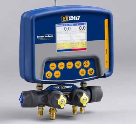
YELLOW JACKET Refrigeration System Analyzer Users Manual - UPC# 40812, 40813 and 40815
←
→
Transcription du contenu de la page
Si votre navigateur ne rend pas la page correctement, lisez s'il vous plaît le contenu de la page ci-dessous
YELLOW JACKET ®
  Refrigeration System Analyzer
          Users Manual
     UPC# 40812, 40813 and 40815
      (Versions 1.06 and higher)

Note: These instructions do not cover the manifold
           attached to the instrument.
Table of Contents
Chapter Title Pg. Chapter Title Pg.
1 Before You Start 3 Features and Specifications 15
Contact and Safety Information 3 Instrumentation Specifications 16
2 Getting Acquainted 4 Warranty Policy 16
Turning the Instrument On 4
and Off
List of Tables
Battery Considerations 4
Table Title Pg.
Keyboard Keys 5
1-1 Safety Information 3
Understanding the Displays 6
1-2 Symbols 4
Using the Temperature and 7
Vacuum Sensors 2-1 Key Functions 5
3 Getting the Job Done 7 6-1 Spare Parts 14
Temperature and Pressure Mode 7
Vacuum Mode 9 List of Figures
Vacuum Sensor Calibration 10 Table Title Pg.
4 Data Logging 10 2-1 Menu Display 4
Begin Logging 10 2-2 Battery Power Symbol 5
Playback and USB Functionality 11 2-3 Low Battery Pop-up Message 5
Erase Files 11 2-4 Menu Display 6
5 Settings 11 2-5 System Analyzer Display 6
Refrigerant Type 11 2-6 P/T Chart Display 6
Temperature Unit 12 2-7 Vacuum Gauge Display 6
Elevation 12 2-8 Data Logging Start-up Display 6
Auto Vacuum Gauge 12 2-9 Set-Up Display 6
Power Saving Mode 12 2-10 Sensor Connections 7
Auto Power Off 12 2-11 Sensors without Boots 7
Battery Type 12 2-12 Sensors with Boots 7
Graph Type 12 3-1 First System Analyzer Display 8
Time Format 12 3-2 2nd System Analyzer Display 8
Time and Date 12 3-3 3rd System Analyzer Display 9
Refrigerant Favorites 12 3-4 Vacuum Gauge Display 9
Zero Pressure 13 3-5 Sensor Calibration Number 10
Exiting the Set-Up Display 13 4-1 Data Logging Menu 10
Settings Shortcut 13 4-2 Data Logging Start-Up Screen 10
6 Maintenance 13 4-3 Data Log Files 11
General Maintenance 13 5-1 (a, b) Set-up Displays 11
Replacing the Batteries 14 5-2 Time & Date Setting Screen 12
Spare Parts 14 5-3 Refrigerant Favorites Set-up 12
Software Updates 14 5-4 Refrigerant Favorites Screen 13
Further Assistance 15 5-5 Settings Shortcut 13
7 Specifications 15 5-6 Battery Access 14
Safety 15 5-7 Battery Servicing 14
2Chapter 1 Table 1-1. Safety Information
Before You Start Warning
● The instrument contains no internal user-
Contacting Ritchie serviceable parts other than batteries that
may be accessed through the battery door.
Do not open the instrument other than open-
To order accessories, receive assistance, or ing the battery door. Have the instrument
locate the nearest YELLOW JACKET distributor. serviced only by Ritchie Engineering Co. or
authorized service centers.
Corporate Office and Mailing Address:
Ritchie Engineering Co, Inc. ● Do not use the instrument if it operates ab-
YELLOW JACKET Products Division normally. Protection may be impaired. When
10950 Hampshire Avenue South in doubt, have the instrument serviced.
Bloomington, MN 55438-2623 U.S.A.
Phone: (952) 943-1300 or (800) 769-8370 ● Refer to warnings supplied with batteries
Fax: (800) 769-8370 acquired for use in this instrument. If the bat-
E-mail: custserv@yellowjacket.com teries are not supplied with warnings, obtain
www.yellowjacket.com them from the manufacturer or supplier.
● Do not operate the instrument or service bat-
Safety Information teries around explosive gas, vapor, or dust.
Use the instrument only as specified in this ● Various refrigerants have been intentionally
manual. Otherwise, the protection provided by excluded for very significant safety reasons.
the instrument may be impaired. Refer to safety Never use refrigerants in this instrument that
information in Table 1-1. are not listed in the Set-up menu.
A Warning identifies conditions and actions that ● The refrigerant database in this unit may
pose hazards to the user. A Caution identifies include refrigerants classified as flammable.
conditions and actions that may damage the If such refrigerants are selected, the operator
instrument or the equipment under test. may need additional certifications and/or
training. Consult your government and legal
authority and comply fully with all require-
ments.
Table 1-1. Safety Information
Warning ● Always wear eye and skin protection when
working with refrigerants. Escaping refriger-
To avoid personal injury or death, follow these ant vapors will present a freezing danger.
guidelines: Do not direct refrigerant vapors venting from
hoses towards the skin.
● Most governments and legal authorities re-
quire that HVAC technicians be trained and ● Maximum Working Pressure: High Side: 700
certified in the safe and proper operation of psia (4.83 MPa)
HVAC tools, such as this instrument. Since
this tool may be connected to many types of ● Maximum Working Pressure: Low Side: 350
equipment through a limitless combination psia (2.41 MPa)
of hoses and fittings, proper training is the
most important element of using this tool ● Because this instrument allows for various
safely. inputs including electrical and mechanical,
care must be taken to observe any ways that
● Read the entire Users Manual before using an electrical shock hazard could develop.
the instrument. Example: Wet or humid conditions, along
with a damaged thermocouple or vacuum
● Use the instrument only as described in the sensor, could allow an electrical path across
Users Manual, otherwise the protection pro- the instrument and over wet hoses. Keep all
vided by the equipment may be impaired. interconnected equipment clean, organized,
and in proper condition. Do not use the in-
● Do not use the instrument if it is damaged. strument if you are not qualified to recognize
Before you use the instrument, inspect the potential electrical faults.
case. Look for cracks or loose components.
cont. next page.......
3Table 1-1. Safety Information Chapter 2
Caution Getting Acquainted
To avoid damage to equipment, follow these
guidelines: Introduction
● Do not allow pressures beyond the specifi- This instrument will clearly and accurately report
cations listed in this manual. critical information needed to properly service re-
frigeration and air-conditioning equipment. With its
● Be aware that internal pressures can many features, time can be saved and the quality
change unintentionally when equipment is of service can be verified through data reports for
customer satisfaction. Some of the most signifi-
stored with pressure in the system during
cant features include:
temperature changes. If sub-cooled liquid
● High accuracy and resolution
refrigerant is trapped in a hose or manifold ● Very fast and sensitive leak detection
with no room for expansion, it may result in ● Robust temperature compensation with fault
dramatic pressure variations with seemingly detection
small temperature changes. Pressures can ● Data logging and downloading for reporting and
reach high enough levels to cause dam- analysis
age to the instrument’s internal pressure ● High durability and weather-resistance
transducers. Release liquid refrigerant from
the hoses and manifold when disconnecting Note that these instructions do not cover the
from a system. manifold attached to the instrument.
● Refer to cautions supplied with batteries
acquired for use in this instrument.
Turning the Instrument On
and Off
● Do not attempt to introduce liquid or
samples heavily laden with oil into the Press and release the key to turn unit on. After
instrument. the logo appears briefly, the instrument will pres-
ent the main menu.
● Read and observe instructions and specifi-
cations related to the batteries used in this Press and hold the key (~two seconds) to turn
instrument that may cause damage to it. unit off.
● Do not use this instrument on systems
containing leak sealing chemicals. These
leak sealants can collect and harden in the
instrument, causing permanent damage.
Table 1-2 Symbols
Important information
Power On/Off
Figure 2-1. Menu Display
T1 Temperature 1
Battery Considerations
T2 Temperature 2
The instrument uses eight AA batteries. The
Indicates that the instrument is user may select batteries of the following types:
REC recording readings (data logging) Alkaline, AA-Lithium, Ni-MH, Ni-Cd, Li-Pol, Li-Ion
from the Setup menu (see Chapter 5). Do not mix
Indicates page-by-page scrolling
||>The illustration below shows three bars that indi- Maximizing Battery Life
cate a fresh or well-charged battery pack. When
the battery weakens, the bars will disappear one- Battery life decays fastest when the DIGITAL
by-one as the battery power decays. When one MANIFOLD display is selected, the vacuum sen-
bar remains, the symbol will turn yellow. When all sor is attached, and the backlight is on. Battery
bars are gone, the batteries are nearly dead and life during data logging is maximized by using
the symbol will turn red. The unit will briefly show high-performance batteries, detaching the vacuum
a pop-up message just before the unit stores all sensor (if not in use), and a short Power Saving
data and then automatically shuts off. Mode time setting is selected.
Keyboard Keys
Note that pressing a key that has not been
Figure 2-2. Battery Power Symbol assigned to a function will result in three, short
beeps.
Table 2-1. Key Functions
Power On/Off (see Chapter 2, Turn-
ing the Instrument On and Off).
Menu Accesses menu of instrument
functions.
Enter Accepts selected functions and
values.
This key will also toggle the instru-
ment data display modes. See
Chapter 3.
Figure 2-3. Low Battery Pop-Up Message
During playback of logged data,
toggles between point-by-point and
Automatic Power Off page-by-page scrolling.
The instrument may automatically turn off after Clear A single press clears the chart set
a period of time. The default is one hour. The point. (See Figure 3-1, item 11)
user may select other settings from ten minutes
to four hours from the Setup menu (see Chapter Press and hold to clear ‘Min.’ and
5). The user may also disable this feature. The ‘Max.’ values. (See Figure 3-1,
Auto Power Off time limit is automatically disabled item 5)
during data logging and is automatically restored Resets vacuum timer to 0:00:00.
once data logging has terminated. (See Chapter 3)
Hold Freezes the data display at the
Power Saving Mode moment the key is depressed when
data is being displayed. A second
The display backlight will fade, darkening the
key press will return the display to
display to save battery life if a key has not been
the normal, dynamic mode (not ac-
pressed for a set period of time. While in Power
cessible during data logging).
Saving Mode, pressing any key turns the display
backlight back to full brightness. Note that Chart Toggles time resolution to display
backlighting is independent from the display Time more or less of the data acquisition
brightness and contrast settings (see Chapter 5) event, enhancing a user’s ability to
which do not affect battery life. see significant events (not accessible
during data logging).
The Power Saving Mode is preset to 10 minutes.
Chart Toggles pressure resolution to fit
From the Setup menu (see Chapter 5), you can
Pres- analog pressure data within the
specify settings from 30 seconds to 60 minutes.
sure display, enhancing a user’s ability to
see significant events.
Low Battery Conditions
Up/Left Assists in selection of values and
The unit will attempt to store all logged data if data points depending on the func-
Down/
low battery power is detected. Once the data is tion feature involved (not accessible
Right
stored, unit will turn off. during data logging).
5Understanding the Displays
Figure 2-4. Menu Display Figure 2-7. Vacuum Gauge Display
(See Chapter 3)
Use the ▲ or ▼ keys to scroll through the menu.
Press the “Enter” key to make a selection.
Figure 2-8. Data Logging
Start-Up Display
Figure 2-5. System Analyzer Display (See Chapter 4)
(See Chapter 3)
Figure 2-6. P/T Chart Display Figure 2-9. Set-Up Display
(See Chapter 5)
This display shows the “P/T” (Pressure/Tempera-
ture) chart for the refrigerant that is selected in the
“Set-Up” display. Use the ▲ or ▼ keys to scroll
through the chart. Press the “Menu” key to exit.
6Using the Temperature and Chapter 3
Vacuum Sensors Getting the Job Done
To use the external temperature and vacuum sen-
sors, plug them into the connectors located on the Temperature and
side of the instrument. The use of rubber connec-
tor boots is optional. They will, however, increase Pressure Mode
the weather resistance of the unit and reduce the
Note: A common mistake is to forget to zero the
amount of dust that could enter at the vacuum
pressure sensors before using the instrument for
connector, if that boot isn’t used. When not in use,
a job, resulting in incorrect pressure readings and
the vacuum and USB connector openings should
calculations. See Chapter 5 - Settings, Zero pres-
be covered with the tethered plugs.
sure, for more information.
The unit will simultaneously display inputs from
four sources:
● T1 Temperature Sensor (Suction line
temperature for superheat)
● T2 Temperature Sensor (Liquid line
temperature for subcooling)
● Low Side Pressure Transducer (internal)
● High Side Pressure Transducer (internal)
Temperature Probes – The system analyzer will
T1 T2 Vacuum USB display readings from any K-type thermocouple
(Plugged) (Plugged) probe with a miniature style
connector (see picture). The
K-type is usually indicated
Figure 2-10. Sensor Connections with a letter K on the con-
nector. The miniature style
thermocouple connectors
have two flat blade contacts. The two blade con-
tacts are different widths to ensure proper polarity.
Plug the blade contacts into the matching slots in
the analyzer.
Your system analyzer includes a pair of K-type
clamp probes for easy pipe temperature measure-
ment.
Figures 3-1, 3-2, and 3-3 show the three digital
manifold displays for monitoring system charging
and operation.
● The first display (see Figure 3-1) presents
Figure 2-11. Sensors without Boots all available data outputs including XY
Time-Pressure charting.
● The second display (see Figure 3-2) is the
same as the first except for the exclusion of
the Temp-1, Temp-2, vapor (Low sat.) and
liquid (High sat.) saturation points.
● The third display (see Figure 3-3) is the same
as the first except for the exclusion of the XY
Time-Pressure charting.
Once the default digital manifold display has been
selected from the main menu, pressing the “Enter”
key will advance through all three displays.
Figure 2-12. Sensors with Boots
7While using any of the digital manifold or
vacuum gauge display screens, press the
UP/LEFT key to activate a pop-up screen
where options can be changed using the
UP/LEFT and DOWN/RIGHT keys. Press
the MENU key to save the selections and
exit the pop-up screen.
9 Superheat: The calculated superheat for
the selected refrigerant.
Subcool: The calculated subcooling for
the selected refrigerant.
Figure 3-1. First System NOTE: These calculations are based
Analyzer Display on the measured pressures and
temperatures.
1 Date and Time. (See Chapter 5 to set).
10 Charted pressure
2 Pressure units. While using any of the digital
manifold or vacuum gauge display screens, 11 Time indication (cursor)
press the UP/LEFT key to activate a pop-up 12 Seconds per samples (sample interval).
screen where options can be changed using Use the “Chart Time” key to toggle this
the UP/LEFT and DOWN/RIGHT keys. value through the available settings.
Press the MENU key to save the selections
and exit the pop-up screen. A small number will show rapid pressure
3 Refrigerant type. While using any of the changes by displaying a short period of
digital manifold or vacuum gauge display time (‘zoom in’). A large number will show
screens, press the UP/LEFT key to activate only slower pressure changes by display-
a pop-up screen where options can be ing a larger period of time (‘zoom out’).
changed using the UP/LEFT and DOWN/ 13 Pressure scale range. Use the “Chart
RIGHT keys. Press the MENU key to save Pres.” Key to toggle pressure resolution
the selections and exit the pop-up screen. to fit analog pressure data within the
4 Battery strength. (See Chapter 2 for battery display, enhancing a user’s ability to see
considerations). significant events. A small range will show
small pressure changes (‘zoom in’). A
5 The minimum and maximum pressures larger range will show only larger pres-
encountered since the memory was last sure changes (‘zoom out’).
cleared. (“Clear” key - typical for high and
low sides). 14 Left Side: Suction pressure (‘Low Side’)
6 Set: The pressure represented by the center Right Side: Discharge pressure
horizontal line on both charts. (‘High Side’)
Crs: (Cursor) The charted pressure marked
by the vertical line on both charts.
7 Left Side: Vapor Saturate. The vapor satura-
tion temperature for the selected refrigerant.
(Also known as dew point)
Right Side: Liquid Saturate. The liquid satu-
ration temperature for the selected refriger-
ant. (Also known as bubble point)
8 Temp-1 (T1): The temperature indicated by
the T1 thermocouple. (For proper superheat
measurement, the T1 probe should be mea-
suring the suction line temperature.)
Temp-2 (T2): The temperature indicated by
the T2 thermocouple. (For proper subcool-
ing measurement, the T2 probe should be
measuring the liquid line temperature.) Figure 3-2. 2nd System Analyzer Display
81 Pressure units. While using any of the
digital manifold or vacuum gauge display
screens, press the UP/LEFT key to activate
a pop-up screen where options can be
changed using the UP/LEFT and DOWN/
RIGHT keys. Press the MENU key to save
the selections and exit the pop-up screen.
2 Discharge pressure (‘High Side’).
3 When data recording is activated, this
indicator will gradually change from red
to blue indicating the size of one page of
data. During playback, it will help the user
to decide whether to move through the
Figure 3-3. 3rd System Analyzer Display data slowly or page-by-page. Adjusting the
sampling rate will affect the amount of data
on each page.
Vacuum Mode 4 Vacuum reading. The message “Out of
range” will appear until the vacuum reaches
Note: If you are using a new vacuum sensor for 25,000 microns.
the first time, the vacuum sensor calibration num- 5 Elapsed time display. Press “Clear” to reset
ber must be entered. The instrument will report counter to 0:00:00.
incorrect data if this is not done. Go to ‘Vacuum
Sensor Calibration Utility’ further down in this 6 Vacuum Units. Vacuum readings can be
chapter for instructions. displayed in Microns, mTorr, Torr, mmHg,
mBar, KPa, and Pa.
The instrument can simultaneously use display
inputs from two sources: If it is desirable to match the pressure units
● Vacuum Sensor with the vacuum units, the pressure units
● Internal Pressure Transducers must be selected before proceeding with
vacuum procedure.
Note: Although the internal pressure transducers
are primarily used for positive pressures, they also While using any of the digital manifold or
give a helpful indication of vacuum activity before vacuum gauge display screens, press the
the vacuum sensor indicates values in the ranges UP/LEFT key to activate a pop-up screen
that are typical when operating vacuum pumps. where options can be changed using the
UP/LEFT and DOWN/RIGHT keys. Press
This screen can be accessed from the main menu, the MENU key to save the selections and
“Vacuum Gauge” selection, or the “Digital Manifold” exit the pop-up screen.
screen by simply plugging in a vacuum sensor if
the “Auto micron meter” is set to “ON”. (See “Set- 7 When recording is activated, the sampling
tings - Auto Vacuum Gauge” in the Setup menu.) rate is displayed here. See “Chapter 4 –
Data Logging” to set the sampling rate.
8 The minimum and maximum pressures
encountered since the memory was last
cleared (“Clear” key). (Typical for high and
low sides.)
9 Left Side: Suction pressure (‘Low Side’).
Press the UP/LEFT key to activate a pop-
up screen where options can be changed
using the UP/LEFT and DOWN/RIGHT
keys. Press the MENU key to save the
selections and exit the pop-up screen.
Figure 3-4. Vacuum Gauge Display
9Vacuum Sensor Calibration Utility Before data logging, verify that the units (tem-
perature, pressure, vacuum) are set to the desired
Whenever a new vacuum sensor is used, the six- values. They cannot be changed when data
digit calibration number printed on the side of the logging is active.
vacuum sensor must be entered. At the screen
shown in Figure 3-4, press and hold the “ENTER”
key. A small pop-up window will appear where
the elapsed time usually appears. The 6 digit
number displayed is the sensor calibration num-
ber currently in memory. These digits need to be
changed to match the number on the new sensor.
The white highlighted digit indicates the digit being
edited. Use the UP/DOWN buttons to change the
highlighted value. When the highlighted value
matches the digit on the sensor label, press the
ENTER button to move to the next digit position.
Repeat until all 6 digits match the digits on the
sensor label. When the sensor number is properly
entered, press the CLEAR button. The sensor
number field will disappear and the elapsed time Figure 4-1. Data Logging Menu
field will reappear.
The instrument is
now ready for use
Begin Logging
with the new sensor. Calibration
Number To activate data logging, select the BEGIN LOG-
Figure 3-5. Sensor Calibration Number GING option from the main Data Logging menu.
The data logging start-up screen will appear,
Connect the gauge to a dry part of the system. allowing you to select the sampling rate. The
The sensor will not work if it becomes filled with sampling rate defines how often readings will
system oil. When the pressure falls into the read- be stored. This screen also shows the available
out range, the numeric readout will appear. data logging memory and the calculated time limit
(based on the current sampling rate).
The vacuum sensor requires approximately 30
seconds of operating (warm-up) time before the When data logging, the sampling rate will dictate
readings are accurate. the chart time setting on the Digital Manifold
screen.
Tips for avoiding sensor contamination
● Inspect fitting for signs of oil before connecting
the 69086 vacuum gauge sensor.
● Keep the sensor vertical when possible.
● Connect the gauge directly to the system,
away from the pump.
● Isolate the pump from the system (and the
gauge) with a valve before turning the pump
off. This is very important when the gauge is
mounted near the pump.
Figure 4-2. Data Logging
Chapter 4 Start-Up Screen
Data Logging After selecting the sampling rate and pressing
ENTER, the digital manifold screen will appear as
usual. When the instrument is logging data, the
Introduction REC icon will flash at the top of the screen and
the red indicator light next to the keypad will flash
Data simultaneously generated by the tempera- periodically.
ture and pressure inputs and vacuum sensor may
be stored in the instrument’s memory for viewing
later via the instrument’s PLAYBACK mode or by
downloading the data to a PC.
10Playback and Chapter 5
USB Functionality Settings
Saved data log files can be viewed using the
“Playback” option. In Playback mode, the digital Introduction
manifold screen will appear just as it did during
the logging process. Use the buttons to scroll This following display presents the instrument
through the recorded data. As you scroll, the settings that may be changed by the user. Use the
date, time, pressures, temperatures, and charts ▲ or ▼ keys to scroll through the settings. Press
will change to match the stored values. To scroll the “Enter” key to select a setting for modification.
faster, use the ENTER key to switch to page by The various setting options will then be available
page scrolling (indicated by |||| icon). Pressing by using the ▲ or ▼ keys to scroll through the
ENTER again will switch back to the slower point options. Once the desired option is displayed,
by point scrolling. press the enter key to activate it and return to the
list of settings.
Instructions for utilizing the USB functionality are
supplied with the software which is available at
www.yellowjacket.com/sa.
Note that data log files, whether viewed on the
analyzer (as shown in Figure 4-3) or on a PC,
will always be identified by the date and time
when the recording was started. Keeping track
of the dates and times of your service jobs and
your recordings will allow for easier playback and
reporting at a later time.
Figure 5-1a. Set-Up Display
Figure 4-3. Data Log Files
Erase File
Use the arrow keys to highlight the data file to be
erased. Press clear to erase.
Figure 5-1b. Set-Up Display
Erase All Files
Refrigerant Type
Press clear to erase all data files.
The proper refrigerant type must be entered in this
field in order to get accurate saturation tempera-
tures and superheat/subcooling calculations. Your
system analyzer is pre-loaded with an extensive
list of refrigerants, identified by their official
ASHRAE numbers. This list of refrigerants can be
updated. See our website at www.yellowjacket.
com/sa for more information about updating the
refrigerant list.
11key. After setting each component, the values are
Warning accepted by, once again, pressing the “Enter” key.
The refrigerant database in this unit may The changes may be discarded by pressing the
include refrigerants classified as flammable. “Menu” key while the pop-up window is active.
If such refrigerants are selected, the operator
may need additional certifications and/or
training. Consult your government and legal
authority and comply fully with all requirements.
Note: As you scroll through the list the names of
flammable refrigerants are highlighted with a red
background. If a flammable refrigerant is selected,
a warning message will appear. This warning
message must be acknowledged before proceed-
ing. Refrigerants that do not have ASHRAE des-
ignations (if any) are designated with abbreviated
trade names.
Figure 5-2. Time & Date Setting Screen
Temperature Unit - Select Fahrenheit
(F) or Celsius (C) degrees. Refrigerant Favorites
Elevation - For accurate refrigerant PT This feature allows customization of the refriger-
data and psia calculations, the operating elevation ant list so only the refrigerants likely to be used
must be entered. The more accurately you set the will be visible in the selection list. Refrigerant
elevation, the more accurate your readings will be. favorites can be changed at any time by going to
Remember to change the elevation setting when the SET-UP menu (second page) and selecting
your job takes you to higher or lower elevations. “Refrigerant Favorites”.
The factory default is zero (sea level).
Auto Vacuum Gauge - Choose
from “ON” or “OFF” (see Chapter 3 - Vacuum
Mode).
Power Saving Mode - Choose
from the available values (discussed in Chapter
2 – Battery Considerations – Power saving mode).
Auto Power Off - Choose from the
available values (see Chapter 2 – Battery Consid-
erations – Auto power off).
Figure 5-3. Refrigerant Favorites Set-up
Battery Type - Choose from the avail-
able types. The refrigerant favorites screen will appear, giving
several options. Favorite refrigerants will be identi-
Graph Type - Choose from the available fied with the standard blue or red background
types. colors. Refrigerants that are not favorites will be
identified with a grey background color.
Time Format - Multiple date display ● The CLEAR button will clear all favorites
formats are supported. This setting will determine except the currently active refrigerant shown
how dates are displayed on the instrument. The at the top of the screen.
factory default is MM/DD/YY.
● The HOLD button will set all refrigerants as
favorites.
● Use the UP/LEFT or DOWN/RIGHT buttons to
Time and Date scroll through the refrigerant list. The yellow
underline will identify the location in the list.
To change a favorite, identify it with the yellow
These settings are modified in a slightly different underline, and press the ENTER button. The
manner: Selecting this setting for modification ENTER button will either remove the refriger-
will open a pop-up window. Each component of ant as a favorite by turning it grey, or make it a
the time and date values may be changed by favorite by turning it red or blue.
using the ▲ or ▼ keys to scroll though them. To ● The MENU button will close the refrigerant
advance to the next component, press the “Enter” favorites screen, saving changes.
12.
Chapter 6
Maintenance
Introduction
Basic operator maintenance is covered in this
chapter. For more extensive maintenance and
for repair, contact Ritchie Customer Service. See
Chapter 1 for contact information.
Figure 5-4. Refrigerant Favorites Screen General Maintenance
Since this instrument may be used in the pres-
Zero Pressure ence of a wide range of chemical liquids and va-
pors, it is recommended that the case be cleaned
The “Zero pressure” setting changes the pressure fairly often with a damp cloth and mild detergent
reading from whatever the unit is reading to zero. such as dish soap.
Selecting this setting for modification will open a
pop-up window with further instructions. Verify that If the unit encounters enough exposure to liquid
manifold pressures have been released before chemicals that the chemical wicks between the in-
performing this procedure. strument boot and the case, immediately remove
the boot and clean the case as described above.
The rubber boot may be immersed in soapy water
Exiting the Set-Up Display to clean it.
To exit the Set-up display, press the “Menu” key. Although the display has a tough, hard-coated,
protective lens, clean the lens carefully, since
Settings Shortcut display clarity is a critical component of this instru-
ment:
While using any of the digital manifold or vacuum
gauge display screens, press the UP/LEFT key ● Normally, the lens can be cleaned as one
to activate a pop-up screen where options can be would clean plastic eyeglass lenses: Use
changed using the UP/LEFT and DOWN/RIGHT a soft, 100% cotton or microfiber cloth and
keys. Press the MENU key to save the selections water or eyeglass lens cleaning solution. Do
and exit the pop-up screen. not use paper products.
● If the lens is very dirty, generously soak a soft
cloth with warm, soapy (dish soap) water and
place the cloth for a couple of minutes over
the lens to loosen any stubborn dirt. Wipe off
excess water with a clean, less dampened,
100% cotton or microfiber cloth, and complete
the cleaning using the normal lens cleaning
method described above.
● If a non-water-soluble substance adheres to
the lens, soak a small piece of soft cloth with
kerosene and place the cloth for a couple of
minutes over the substance to loosen it. Gen-
Figure 5-5. Settings Shortcut Screen tly dab the loosened substance with clean,
less kerosene-dampened pieces of 100%
cotton cloth until the substance is lifted. Allow
to dry and then complete the cleaning using
the normal lens cleaning method described
above.
13Replacing the Batteries Turn the unit off. Rotate the hook (1) out of the
way of the battery door. Unscrew the battery door
thumbscrew (2) and remove the battery door. Lift
The main batteries will need to be replaced on the battery pack out somewhat to allow access to
a routine basis. Battery performance issues are the battery connection (3). Reconnect the battery
discussed in Chapter 2. The coin cell battery pack. Tuck the battery harness to the side of the
maintains the time and date information. It may battery compartment as shown if Figure 6-2 as
need to be replaced once or twice in the life the battery assembly is lowered into the battery
of the instrument. To exit the Set-up display, press compartment.
the “Menu” key.
Coin Cell Battery
If the unit is not maintaining the correct time and
date, follow the instructions above to remove the
main battery pack and expose the coin cell battery
through an access hole in the floor of the battery
compartment. Using a tool such as a small screw-
driver, deflect the battery to the side until a corner
of the battery springs up slightly. It may be lifted
out of the battery socket at this point. Reverse this
procedure to install the fresh battery.
Spare Parts
Figure 5-6. Battery Access
Spare parts are listed in Table 6-1. See Chapter
1 for contact information. See the included TITAN
manifold instructions for manifold-related spare
parts.
Table 6-1 Spare Parts
UPC# Description
40820 Battery Holder, ‘AA’ Size, 2x4
40821 System Analyzer Instrument Boot
40823 System Analyzer Battery Door
40824 System Analyzer Bumper,
Plugs, & Sensor/Probe Boots
40827 USB cable
Figure 5-7. Battery Servicing
69101 Vacuum Sensor/Cord Assembly
69217 “K-Type” Clamp Probe (10 ft.)
Main Batteries
See Chapter 7 for battery type specifications.
Software Updates
Details related to software updates are available
Warning online at www.yellowjacket.com/sa or by contact-
ing Ritchie Engineering. See Chapter 1 for contact
Because this instrument allows for various information.
inputs including electrical and mechanical,
care must be taken to observe any ways that
an electrical shock hazard could develop.
Example: Wet or humid conditions, along with
a damaged thermocouple or vacuum sensor,
could allow an electrical path across the instru-
ment and over wet hoses. Keep all intercon-
nected equipment clean, organized, and in
proper condition. Do not use the instrument
if you are not qualified to recognize potential
electrical faults.
14When Further Assistance Features
is Needed Display Digital/analog redundancy for
Graphics pressure values; adjustable
If this manual does not include information need- chart resolutions to display
ed to resolve any difficulty you may experience: more or less data; three screen
layouts to facilitate various
1. Examine the instrument for any cracks viewing distances
or other damage. It may be necessary to
remove the boots and battery door for a Superheat Automatically calculated
complete inspection. If damage is found, and Subcool
contact Ritchie Engineering. See the Max. Displays and records the maxi-
contact information in Chapter 1. and Min. mum and minimum
2. Replace the sensors, probes, and/or Pressures pressures
batteries.
3. Additional technical information may be Hold Holds current reading and
available at www.yellowjacket.com/sa. Function scrolls back to past readings
4. It may be necessary to return the instru-
Refrigerant 98 NIST refrigerant profiles
ment to Ritchie if the information in this
Database included; upgradeable
manual and the help provided here does
not resolve the issue. If this is the case, Data Adjustable time intervals from
determine the version and serial numbers Logging 0.1 to 10 seconds; minimum
for your instrument by accessing the of 24 hours at 1.0 second
set-up screen. If the unit is not functional, intervals
the serial number is printed on the floor of
the battery compartment. After you have Computer Downloads data log files for
secured your version and serial number, Interface equipment performance reports
see the contact information in Chapter 1 via USB port
to obtain an RMA number and arrange for Real-Time Real-time clock for time and
service. For warranty information, please Clock date stamping of equipment
see the warranty listed at the end of this performance reports
Users Manual.
Temperature Two, temperature compen-
Sensors sated, continuity fault
Chapter 7 detecting, K-type temperature
sensor ports
Specifications Vacuum Full scale via pressure trans-
Sensor ducers and micron gauge; Pro-
prietary sensor: part # 69087
Safety Pressure Two transducers plumbed to
Transducers manifold
Maximum Liquid and/or High side: 700 psia
Manifold Mates with TITAN 4-Valve
Vapor Pressure Low Side: 350 psia
Manifold
Pressure Press key in setup menu to
Physical Specifications Zeroing zero
Elevation Enter elevation in setup menu
Compensation for psia compensation
Operating -4 to 122°F (-20 to 50°C)
Temperature PT Chart All installed refrigerant
Storage -20 to 170°F Reference profiles may be displayed
Temperature Screen
Size 8.3” wide x 6.7” tall x 3.6” thick Batteries AA size (Quantity: 8); Alkaline,
(21 x 17 x 9 cm), manifold (Main) NiCd, NiMH, A-A Lithium, Li
excluded Ion, Li Pol; One day of continu-
ous operation when using fresh
Weight 3.2 lbs (1.45 kg), manifold alkaline batteries or healthy
excluded rechargeable batteries
Display unit Digital color TFT display with Battery Coin type lithium clock bat-
adjustable brightness and con- (Coin Cell) tery for maintaining time and
trast behind anti-glare, scratch date: Panasonic CR2032 or
resistant, protective lens equivalent.
15Features, cont.
Instrumentation
Housing Highly weather resistant; glass-
fiber reinforced, engineering Specifications
grade thermoplastic Pressure Low side: 0.1 psi, 0.01bar,
Hook Integral hook swivels 360° and Sensing 1kPa, 0.01MPa, 0.01kg/cm²
stows when not used Resolution
High side: 0.1 psi, 0.01bar,
Leaks Due to high accuracy and reso- 1kPa, 0.01MPa, 0.01kg/cm²
lution of the pressure transduc- Pressure 0.5% of full scale at 25ºC
ers, leaks in equipment can be Sensing
quickly sensed Accuracy 1% of full scale 55ºF to 130ºF
2% of full scale -40ºC to 120ºC
Working Low side: 0 – 350 psia
Pressure
High side: 0 – 700 psia
Proof Tolerable pressure without
Pressure internal damage
Low side: 1000 psi
Warranty Policy High side: 1000 psi
Burst Tolerable pressure without loss
The YELLOW JACKET® Refrigeration System Pressure of seal
Analyzer from Ritchie Engineering Company,
Inc. is guaranteed to be free from material and Low side: 1500 psi
workmanship defects for a period of two years. High side: 1500 psi
All other YELLOW JACKET® products included
in this package are guaranteed to be free from Temperature -100°F to 600°F
material and workmanship defects for a period of Sensor Range
(Instrument)
one year. These guarantees do not cover prod-
ucts that have been altered, abused, misused or Temperature 0.1°F or °C
improperly maintained. Display
Resolution
Not all catalogued products are stocked and eli- Temperature ±1.8°F (±1°C)
gible for return. Please check with your YELLOW Accuracy
JACKET representative or the factory for more (Instrument)
information.
Vacuum Shows two most significant
Display digits in microns (25xxx-
All returns must have an RGA number and proof
Resolution 10xxx, 99xx-10xx, 99x-10x, 99-
of purchase/copy of invoice. Please obtain an
10); other units - direct conver-
RGA number from Ritchie Engineering Customer
sions from the micron value
Service by calling 800-769-8370.
Vacuum 20% of reading
All returns must be pre-paid. Accuracy
Ritchie Engineering Co., Inc. - YELLOW JACKET Products Division
10950 Hampshire Avenue South
Bloomington, MN 55438 U.S.A.
Phone: (800)769-8370 or (952)943-1333
Fax: (800)322-8684
E-mail: custserv@yellowjacket.com
Web: www.yellowjacket.com
©2009-2014 Ritchie Engineering Co., Inc. Printed in USA P/N 500935_B
16YELLOW JACKET®
Analizador de sistemas de refrigeración
Manual del usuario
UPC# 40812, 40813 y 40815
Nota: estas instrucciones no cubren el colector
conectado al instrumento.Índice
Capítulo Título Pág. Capítulo Título Pág.
7 Especificaciones 14
1 Antes de comenzar 3
Información de contacto de Ritchie 3 Seguridad 14
Información de seguridad 3 Especificaciones físicas 14
2 Conocer el instrumento 4 Características 15
Introducción 4 Especificaciones de 15
la instrumentación
Encender y apagar el instrumento 4
Política de garantía 16
Consideraciones acerca de las pilas 4
Teclado 5 Lista de tablas
Descripción de las pantallas 6 Tabla Título Pág.
Cómo usar los sensores de tem- 7 1-1 Información de seguridad 3
peratura y vacío
1-2 Símbolos 4
3 Realizar el trabajo 7
2-1 Funciones clave 5
Modos de temperatura y presión 7
6-1 Repuestos 13
Modo de vacío 9
4 Registro de datos
Introducción
10
10
Lista de figuras
Tabla Título Pág.
Comenzar el registro 10
2-1 Pantalla de menú 4
Reproducción y funcionalidad USB 10 2-2 Símbolo de carga de las pilas 5
Eliminar archivo 10 2-3 Mensaje emergente de pilas bajas 5
Eliminar todos los archivos 10 2-4 Pantalla de menú 6
5 Configuraciones 11 2-5 Pantalla del analizador del 6
sistema
Introducción 11
2-6 Pantalla de gráficos de P/T 6
Refrigerant Type (tipo de refrigerante) 11 2-7 Pantalla del vacuómetro 6
Temperature Unit (unidad 11 2-8 Inicio del registro de datos 6
de temperatura)
2-9 Pantalla Set-Up 6
Elevation (elevación) 11 2-10 Conexiones del sensor 7
Auto Vacuum Gauge (vacuómetro 11 2-11 Sensores sin accesorios 7
automático)
2-12 Sensores con accesorios 7
Power Saving Mode (modo 11
3-1 Primera pantalla del analizador 8
de ahorro de energía)
del sistema
Auto Power Off (apagado automático) 11 3-2 Segunda pantalla del 8
Battery Type (tipo de pilas) 11 analizador del sistema
3-3 Tercera pantalla del analizador 8
Graph Type (tipo de gráfico) 11
del sistema
Time Format (formato de tiempo) 11 3-4 Pantalla del vacuómetro 9
Time and Date (hora y fecha) 12 3-5 Número de calibración del sensor 9
Favoritas Refrigerante 12 4-1 Menú Data Logging (registro 10
de datos)
Zero Pressure (presión cero) 12
4-2 Pantalla de inicio de registro 10
Salir de la pantalla Set-Up 12 de datos
Configuración de acceso directo 12 4-3 Archivos de registro de datos 10
6 Mantenimiento 13 5-1 (a, b) Pantallas Set-up 11
Introducción 13 5-2 Pantalla de configuración 12
de hora y fecha
Mantenimiento general 13
5-3 Set-up de refrigerante favoritos 12
Reemplazo de las pilas 13 5-4 Pantalla de refrigerante favoritos 12
Repuestos 14 5-5 Configuración de acceso directo 12
Actualizaciones de software 14 6-1 Acceso a las pilas 13
2 Asistencia adicional 14 6-2 Reemplazar las pilas 13Capítulo 1 Tabla 1-1.
Antes de comenzar Información de seguridad
Advertencia
Información de contacto ● El instrumento no contiene ninguna parte interna
de Ritchie que pueda reemplazar el usuario, a excepción
de las pilas, a las que se puede acceder a
través de la tapa de las pilas. No abra ninguna
Para pedir accesorios, recibir asistencia o localizar al parte del instrumento a excepción de la tapa
distribuidor más cercano de YELLOW JACKET. de las pilas. El instrumento debe ser reparado
únicamente por personal de Ritchie Engineering
Oficina corporativa y dirección postal: Co. o de algún centro de servicios autorizado.
Ritchie Engineering Co., Inc. ● No utilice el instrumento si funciona de forma
YELLOW JACKET Products Division anómala. La protección podría verse afectada.
10950 Hampshire Avenue South Cuando tenga alguna duda, solicite que le
Bloomington, MN 55438-2623 EE. UU. revisen el instrumento.
Teléfono: (952) 943-1300 u (800)769-8370
Fax: (800) 769-8370 ● Consulte las advertencias suministradas
Correo electrónico: custserv@yellowjacket.com con las pilas adquiridas para utilizar con
www.yellowjacket.com este instrumento. Si las pilas no incluyen
advertencias, obténgalas del fabricante
o proveedor.
Información de seguridad
● No utilice el instrumento o cambie las pilas
cerca de gas explosivo, vapor o polvo.
Utilice el instrumento siguiendo las instrucciones
indicadas en este manual. De lo contrario, se podría ● Se han excluido deliberadamente varios
ver afectada la protección proporcionada por el instru- refrigerantes por razones importantes de
mento. Consulte la información de seguridad seguridad. No utilice nunca en este instrumento
de la Tabla 1-1. refrigerantes que no estén enumerados en el
menú Set-up.
Un párrafo de Advertencia indica condiciones y
acciones que pueden ser peligrosas para el usuario. ● La base de datos de refrigerantes de esta
Un párrafo de Precaución indica condiciones y unidad puede incluir refrigerantes clasificados
acciones que pueden causar daños al instrumento como inflamables. Si se seleccionan estos
o el equipo que se esté probando. refrigerantes, el operador puede necesitar cer-
tificaciones y/o formación adicionales. Consulte
con las autoridades legales y gubernamentales
Tabla 1-1. y cumpla con todos los requisitos.
Información de seguridad ● Cuando trabaje con refrigerantes, lleve puesto
Advertencia en todo momento protección de ojos y piel.
El escape de vapores de refrigerante puede
Siga estas directrices para evitar lesiones o la ocasionar peligros de congelación. No dirija
muerte: los vapores extraídos de las mangueras hacia
la piel.
● La mayoría de los gobiernos y autoridades
legales exigen que los técnicos de HVAC ● Presión de trabajo máxima: Lado alto:
estén formados y certificados en cómo utilizar 700 psia (4,83 MPa)
las herramientas del HVAC, como este ● Presión de trabajo máxima: Lado bajo:
instrumento, de forma adecuada y segura. 350 psia (2,41 MPa)
Como esta herramienta se puede conectar a
diferentes tipos de equipos por medio de una ● Como este instrumento admite varias entradas
gran variedad de combinaciones de mangueras eléctricas y mecánicas, se debe poner mucha
y conectores, una formación adecuada es el atención en evitar cualquier riesgo de descarga
elemento más importante a la hora de utilizar eléctrica que pudiera surgir. Por ejemplo: las
esta herramienta con seguridad. condiciones de humedad, junto con un sensor
de vacío o termopar dañado, podrían permitir
● Lea el manual del usuario completo antes de una vía eléctrica a través del instrumento y
utilizar el instrumento. sobre las mangueras mojadas. Mantenga
● Use el instrumento sólo de la forma descrita en limpio, organizado y en condiciones adecuadas
el Manual del usuario; de lo contrario, podría todo el equipamiento interconectado. No utilice
verse afectada la protección proporcionada por el instrumento si no está cualificado para
el equipo. reconocer posibles fallos eléctricos.
cont. página siguiente.......
● No utilice el instrumento si está dañado. Antes
de utilizar el instrumento, inspeccione el
embalaje. Compruebe que no haya
componentes rotos o sueltos.
3Tabla 1-1. Capítulo 2
Información de seguridad Conocer el instrumento
Precaución
Siga estas directrices para evitar daños en el
Introducción
equipo: Este instrumento comunicará con claridad y precisión
● No permita presiones por encima de las especi- la información crucial necesaria para el mantenimien-
to adecuado del equipamiento de refrigeración y aire
ficaciones enumeradas en este manual.
acondicionado. Gracias a sus muchas característi-
● Tenga en cuenta que, durante alteraciones de cas, se puede ahorrar tiempo y se puede verificar la
temperatura, las presiones internas pueden calidad del mantenimiento por medio de informes de
cambiar de forma no intencionada cuando el datos para mayor satisfacción del cliente. Algunas
equipo está almacenado con presión en el de las características más significativas incluyen:
● Alta precisión y resolución
sistema. Si el refrigerante líquido subenfriado
● Detección muy rápida y sensible de fugas
está atrapado en una manguera o colector sin
● Compensación sólida de temperatura con
espacio para la expansión, se pueden producir
detección de fallos
variaciones drásticas de presión con cambios
● Registro y descarga de datos para informes
de temperatura aparentemente pequeños.
y análisis
Las presiones pueden alcanzar niveles lo ● Alta durabilidad y resistencia a las inclemencias
suficientemente altos para causar daños a los del tiempo
transductores de presión internos del instru-
mento. Libere el refrigerante líquido de Tenga en cuenta que estas instrucciones no cubren
las mangueras y colectores cuando lo el colector conectado al instrumento.
desconecte de un sistema.
● Consulte las precauciones suministradas con Encender y apagar
las pilas adquiridas para utilizar con este
instrumento. el instrumento
● No intente introducir líquido o muestras excesi- Presione y suelte la tecla para encender la
vamente cargadas con aceite en el instrumento. unidad. Después de que aparezca el logotipo breve-
mente, el instrumento presentará el menú principal.
● Lea y siga las instrucciones y especificaciones
correspondientes a las pilas utilizadas en este Presione y mantenga presionada la tecla (dos
instrumento que puedan causarle daños. segundos aproximadamente) para apagar la unidad.
● No utilice este instrumento en sistemas que
tengan precintos químicos contra fugas. Estos
precintos contra fugas pueden acumularse y
endurecerse en el instrumento, lo que ocasiona
daños permanentes.
Tabla 1-2. Símbolos
Información importante
Botón de encendido/apagado
T1 Temperatura 1
Figura 2-1. Pantalla de menú
T2 Temperatura 2
Consideraciones acerca
Indica que el instrumento está gra- de las pilas
REC bando las lecturas (registro de datos)
El instrumento utiliza ocho pilas AA. El usuario puede
Indica el modo de desplazamiento seleccionar en el menú Setup (configuración) pilas de
||>La ilustración siguiente muestra tres barras que Maximizar la vida de las pilas
indican un paquete de pilas nuevo o bien cargado.
Cuando las pilas se debilitan, las barras desaparecen Las pilas se agotan más rápidamente cuando
una a una según va decayendo la potencia de las
está seleccionada la pantalla DIGITAL MANIFOLD
pilas. Cuando sólo queda una barra, el símbolo se
(colector digital), cuando está conectado el sensor
vuelve amarillo. Cuando desaparecen todas las bar-
ras, las pilas están casi agotadas y el símbolo cambia de vacío y cuando está encendida la iluminación
a rojo. La unidad mostrará brevemente un mensaje de fondo. La vida de las pilas durante el registro
emergente antes de almacenar los datos y apagarse de datos se maximiza utilizando pilas de alto
automáticamente. rendimiento, separando el sensor de vacío (si no se
está utilizando) y estableciendo un valor de tiempo
pequeño en el modo de ahorro de energía.
Teclado
Figura 2-2. Símbolo de carga de las pilas
Tenga en cuenta que presionar una tecla que no haya
sido asignada a una función producirá tres pitidos cortos.
Tabla 2-1. Funciones clave
Encendido/apagado (consulte el
Capítulo 2: Encender y apagar el
instrumento)
“Menu” Acceso al menú de las funciones
del instrumento.
“Enter” Acepta las funciones y valores
seleccionados.
Esta tecla también intercambia los
modos de presentación de datos del
instrumento. Consulte el Capítulo 3.
Figura 2-3. Mensaje emergente Durante la reproducción de los datos
de pilas bajas registrados, cambia entre despla-
zamiento punto por punto y página
Apagado automático por página.
“Clear” Presionar una vez elimina el punto
El instrumento se puede apagar automáticamente
de referencia del gráfico. (Consulte
después de un periodo de tiempo. El valor predeter-
la Figura 3-1, elemento 11).
minado es una hora. El usuario puede seleccionar
otra configuración, desde diez minutos a cuatro horas Presione y mantenga presionada
en el menú Setup (consulte el Capítulo 5). El usuario esta tecla para eliminar los valores
también puede desactivar esta función. El límite del ‘Min.’ y ‘Max.’ (consulte la Figura 3-1,
apagado automático se desactiva automáticamente elemento 5).
durante el registro de datos y se vuelve a restablecer Restablece el temporizador de vacío
una vez terminado el registro de datos. a 0:00:00. (Consulte el Capítulo 3).
“Hold” Mientras se muestran los datos,
Modo de ahorro de energía presionar esta tecla congela la
presentación de datos. Presionar la
La iluminación de fondo de la pantalla baja de
tecla una segunda vez devolverá
intensidad y se oscurece para ahorrar vida de las
la presentación al modo dinámico
pilas si no se presiona ninguna tecla durante un
normal (no accesible durante el
periodo de tiempo establecido. Mientras se está en
registro de datos).
el modo de ahorro de energía, al presionar alguna
tecla se vuelve a iluminar la pantalla con todo su “Chart Time” Cambia la resolución de tiempo para
brillo. Tenga en cuenta que la iluminación de fondo mostrar más o menos del evento de
es independiente de las configuraciones de brillo adquisición de datos, lo que mejora
y contraste de la pantalla (consulte el Capítulo 5) las posibilidades del usuario para ver
que no afectan a la vida de las pilas. eventos significativos (no accesibles
durante el registro de datos).
El modo de ahorro de energía está preconfigurado
en 10 minutos. Se puede cambiar la configuración “Chart Cambia la resolución de presión para
de 30 segundos a 60 minutos en el menú Setup Pressure” ajustar los datos de presión analógica
(consulte el Capítulo 5). en la pantalla, lo que mejora las posi-
bilidades del usuario para ver eventos
significativos.
Situación de pilas bajas
“Up/Left” Ayuda en la selección de valores y
La unidad intentará almacenar todos los datos regis- (arriba/izqui- puntos de datos dependiendo de la
trados cuando se detecte que la potencia de las pilas erda) característica de la función implicada
es baja. Una vez almacenados los datos, la unidad (no accesible durante el registro de
se apagará. “Down/Right” datos).
(abajo/dere-
cha)
5Descripción de las pantallas
Figura 2-4. Pantalla de menú Figura 2-7. Pantalla del vacuómetro
(Consulte el Capítulo 3)
Utilice las teclas ▲ o ▼ para desplazarse por el
menú. Presione la tecla “Enter” para realizar una
selección.
Figura 2-8. Registro de datos
Pantalla de inicio
(Consulte el Capítulo 4)
Figura 2-5. Pantalla del analizador
del sistema
(Consulte el Capítulo 3)
Figura 2-9. Pantalla Set-Up
(Consulte el Capítulo 5)
Figura 2-6. Pantalla de gráficos de P/T
Esta pantalla muestra el gráfico de “P/T” (Presión/
Temperatura) del refrigerante seleccionado en la
pantalla “Set-Up”. Utilice las teclas ▲ o ▼ para
desplazarse por el gráfico. Presione la tecla “Menu”
para salir.
6Cómo usar los sensores Capítulo 3
de temperatura y vacío Realizar el trabajo
Para utilizar los sensores de temperatura y vacío
externos, conéctelos a los conectores situados en
el lateral del instrumento. El uso de accesorios de Modos de temperatura
conectores de goma es opcional. Sin embargo,
aumentarán la resistencia de la unidad a las
y presión
inclemencias del tiempo y reducirán la cantidad de
Nota: un error común es olvidar poner a cero los
polvo que puede entrar en el conector de vacío si
no se utilizan los accesorios. Cuando no se utilicen, sensores de presión antes de utilizar el instrumento
las aberturas del conector USB y de vacío deberán para un trabajo, lo que ocasionará una lectura y
cubrirse con las tapas de enchufes. cálculos de presión incorrectos. Para obtener más
información consulte el Capítulo 5 - Configuraciones,
Presión cero.
La unidad mostrará simultáneamente entradas de
cuatro fuentes:
● Sensor de temperatura T1 (Temperatura de línea
de succión para calor máximo)
● Sensor de temperatura T2 (Temperatura de línea
de líquido para frío mínimo)
● Transductor de presión del lado bajo (interno)
● Transductor de presión del lado alto (interno)
T1 T2 Vacío USB
Sondas de temperatura: el analizador del sistema
(conectado) (conectado) mostrará lecturas de cualquier sonda termopar tipo
K con un conector estilo
miniatura (consulte la imagen).
Figura 2-10. Conexiones del sensor
El tipo K normalmente está
indicado con la letra K en el
conector. Los conectores ter-
mopar estilo miniatura tienen
dos contactos de hélice planos. Los dos contactos
de hélice tienen anchuras diferentes para asegurar la
polaridad adecuada. Conecte los contactos de hélice
en las ranuras adecuadas del analizador.
Su analizador del sistema incluye un par de abraza-
deras de tipo K sondas para mediciones de tempera-
tura de tubería fáciles.
Las Figuras 3-1, 3-2 y 3-3 muestran las tres
pantallas de colectores digitales para controlar la
carga y funcionamiento del sistema.
Figura 2-11. Sensores sin accesorios ● La primera pantalla (vea la Figura 3-1) presenta
todas las salidas de datos disponibles incluyendo
el gráfico de tiempo-presión XY.
● La segunda pantalla (vea la Figura 3-2) es la
misma que la primera excepto por la exclusión
de los puntos de saturación Temp-1, Temp-2,
vapor (sat. baja) y líquido (sat. alta).
● La tercera pantalla (vea la Figura 3-3) es la
misma que la primera excepto por la exclusión
del gráfico de tiempo-presión XY.
Una vez que la pantalla del colector digital predeter-
minada ha sido seleccionada en el menú principal,
presionar la tecla “Enter” permitirá avanzar por las
tres pantallas.
Figura 2-12. Sensores con accesorios
7Vous pouvez aussi lire