Dayton AC Electromagnetic Brake Motor
←
→
Transcription du contenu de la page
Si votre navigateur ne rend pas la page correctement, lisez s'il vous plaît le contenu de la page ci-dessous
Dayton®
AC Electromagnetic Brake Motor

      Please read and save these instructions. Read carefully
      before attem pting to assem ble, install, operate or
      m aintain the product described. Protect yourself and
      others by observing all safety inform ation. Failure to
      com ply w ith instructions could result in personal injury
      and/or property dam age. Retain instructions for future
      reference.

Form 5S7150     Printed in Korea      SUI100
                9665                  07/12
                Version 0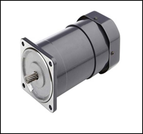
E
Motor Specifications
N Horsepower Rating See SKU Spec. Table 2
G Voltage Rating See SKU Spec. Table 2
L Line Frequency 60Hz
I Enclosure Rating See SKU Spec. Table 2
S
AC Speed Control Ready NO
H
Motor Rotation CW / CCW
Operating Temperature Range -10°C to 40°C
Service Factor 1.0
Duty 30 Minutes
UL Thermal Device Protected
Safety Approval
Motor - Recognition
Motor Capacitor1 Value See SKU Spec. Table 2
2
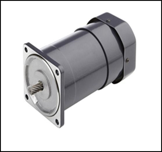
Motor Output Shaft Custom Helical (Gear Screw)
Table 1
Notes: 1) A motor capacitor is supplied with each motor.
2) The motor has a special helical shaft design which is intended for
use with a specific gearbox series.
Do not try to assemble the motor
Warning to unauthorized gearbox.
Motor
Voltage Full Load Enclosure Capacitor
SKU No. HP Capacitor
AC Amps Rating Mounting
MFD / VAC
23L372 1/30 115 0.55 TENV 8.0 / 250 External
23L373 1/30 220 0.28 TENV 2.0 / 450 External
23L381 1/19 115 0.78 TENV 12.0 / 250 External
23L382 1/19 220 0.45 TENV 3.5 / 450 External
23L390 1/12 115 1.23 TEFC 20.0 / 250 External
23L391 1/12 220 0.62 TEFC 5.0 / 450 External
23L399 1/8 115 1.86 TEFC 30.0 / 250 External
23L401 1/8 220 0.98 TEFC 7.0 / 450 External
Table 2
2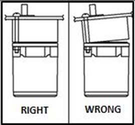
Gearbox Assembly
1.   Position the assembly face of gearbox over
     the motor shaft face as shown to the right.
     Note: The motor shaft has not entered
           the gearbox opening at this point.
2.   Carefully lower gearbox until the motor shaft
     gently touches the internal gearing.
3.   Slowly turn gearbox when assembling to the
     motor to ensure the helical motor shaft meshes with
     the gearbox.
                                                                           Fig. 1
 Gearbox Shaft and Lead Orientation
 Once the faces of gearbox and motor are touching, the gearbox can be rotated to obtain
 the required output shaft and lead wire orientation.

                             Special care must be taken while assembling not to exert
            Caution          excessive force on the motor shaft between the gearbox and
                             motor. Doing so can result in damage causing abnormal noise
                             and shortened product life.

 Correct Procedure to Connect Gearbox to Motor Face
 Four screws are used to connect the gearbox to motor face. The correct screw
 placement sequence and tighten procedure must be followed to prevent damage to the
 gearing:

                                                               Fig. 3

                    Fig. 2

       1.    Hand-tighten the screws that lock the gearbox to motor face in diagonal
             sequence.
       2.    Check to insure the gearbox rests flat against motor face, and that there is no
             air gap between the two faces.
       3.    Tighten the screws to recommended torque value.

            Caution      Failure to follow procedure may damage gearbox
                         internals

                                                3
Parallel Gearmotor Mounting
Fig. 4
The mechanical hardware kit is located inside gearbox carton. This hardware has two
purposes:
• Fasten the Gearbox to the Motor Face
• Fasten the Gearbox to a Mounting Plate
Hardware kit includes Screw (M5*P0.8*L55, M5*P0.8*L65, M5*P0.8*L100, M6*P1.0*L75,
M6*P1.0*L85, M6*P1.0*L95, M6*P1.0*L122), Washer (M5, M6, M8), Nut (M5, M6, M8),
and Key((4*4*L25(1R), 5*5*L25(1R), 6*6*L27.5(1R))
For 1/30 to 1/8 Hp Gearmotor models, the maximum plate thickness is 3/16” and
optional mounting brackets (not provided), 23L574, 23L575, 23L576 are available in
the catalog. For 1/4 Hp Gearmotors, the maximum mounting plate thickness is 1/4”.
Right Angle Gearmotor Mounting
Fig. 5
The mechanical hardware kit is used to connect the gearbox to the motor face. Optional
bolts (not supplied) are required to fasten gearmotor to a mounting plate. Review the
instruction sheet supplied inside gearbox carton for recommended mounting hole
dimensions and mounting bolt size.
4Gearmotor Location
Totally Enclosed gearmotors are used in harsher environment where damp
and dirty conditions may exist. Totally enclosed gearmotors are not
waterproof.
Use only UL listed Hazardous Location motors for service in Hazardous
Locations as defined in Article 500 of the NEC.
The temperature around the gearmotor should not exceed 104°F (40°C).
Minimum temperature is 14°F (-10°C).
The minimum Clearance Space for gearmotors with external fans requires a
minimum 1/2” clearance for adequate air flow for the fan to function properly.
Fig. 6
Minimum Wire Size Table for Single Phase Motor Connections
Motor 25 FT 50 FT 100 FT 150 FT
HP 115V 230V 115V 230V 115V 230V 115V 230V
1/8 14(18) 14 (18) 14 14(18) 12 14(18) 10 14(16)
1/6 14(16) 14 (18) 12 14(18) 10 14(16) 6 14
1/4 14 14 (18) 10 14(16) 8 14 6 12
1/3 14 14 (18) 10 14(16) 8 14 6 12
1/2 12 14 (18) 8 14 6 12 4 10
Table 3
Note:
1. NEC Article 310-5 Minimum conductor size for general wiring at 115 to 440VAC
is No. 14 AWG.
2. Above wire sizes are based on approximately 5% voltage drop during starting;
copper conductors; and 75°C type THHW, THW, THWN, RH, RHW insulation,
etc.
3. Type S, SO, SJ, SJO, etc, flexible cable wire sizes. See NEC Article 400 for
ampacity.
Power Source
Voltage, frequency and phase of the power supply must correspond to that shown on the
motor nameplate. Low voltage can reduce performance and cause overheating.
5Wire Diagram for 23L372, 23L381, 23L390, 23L399
R0 = 10~200Ω (Min. 1/4W), C0=0.1~0.33uF(AC125WV or AC250WV
Fig. 7
Wire Diagram for 23L373, 23L382, 23L391, 23L401
R0 = 10~200Ω (Min. 1/4W), C0=0.1~0.33uF(AC125WV or AC250WV
Fig. 8
6Repair & Accessory Parts
Motor Capacitor
SKU No. ITEM DESCRIPTION HP
MFD / VAC
23L570 Run Capacitor 1/12 20.0 / 250
36N467 Run Capacitor 1/30 8.0 / 250
36N468 Run Capacitor 1/30 2.0 / 450
36N469 Run Capacitor 1/19 12.0 / 250
36N470 Run Capacitor 1/19 3.5 / 450
36N471 Run Capacitor 1/12 5.0 / 450
36N472 Run Capacitor 1/8 30.0 / 250
36N473 Run Capacitor 1/8 7.0 / 450
23L574 Mounting Bracket 1/30
23L575 Mounting Bracket 1/19
23L576 Mounting Bracket 1/12 & 1/8
Table 4
7Trouble Shooting Tips:
Symptom Possible Cause(s) Corrective Action
Motor fails to start Blown fuse Replace fuse. Check for
Grounded winding
Voltage too low at motor Increase wire size. Check for poor
connections
Improper connections Check connections against wiring
diagram.
Motor overloaded Reduce load or increase motor size
Defective motor Repair or replace
Motor stalls during Overload Reduce load or increase
Operation Motor size
Unit overheats while Overloaded Reduce load, increase
Running under load Motor size
Faulty Connection Check and Tighten connections
Dirt blocking Clean motor
Ventilation openings
High or low voltage Check voltage at motor
Defective motor Repair or replace
Unit’s operating speed Supply voltage has dropped Correct cause of low supply voltage
drops
Load increased Reduce load
Loose electrical Tighten connections
connections
Motor vibrates or Is Worn, damaged or Repair or replace motor
excessively noisy overloaded bearings
Table 5
8Initial Inspection and Handling
After opening the carton, look for concealed damage. If concealed damage is
found, then immediately file a claim with the carrier.
Check the motor nameplate to verify that data conforms to specifications of
motor ordered.
Limited Warranty Statement
DAYTON ONE-YEAR LIMITED WARRANTY DAYTON® PERMANENT SPLIT CAPACITOR
TYPE MOTORS ARE WARRANTED BY DAYTON ELECTRIC MFG. CO (DAYTON) TO ORIGINAL
USER AGAINST DEFECTS IN WORKMANSHIP OR MATERIALS UNDER NORMAL USE FOR ONE
YEAR AFTER DATE OF PURCHASE. ANY PART WHICH IS DETERMINED TO BE DEFECTIVE IN
MATERIAL OR WORKMANSHIP AND RETURNED TO AN AUTHORIZED SERVICE LOCATION, AS
DAYTON DESIGNATES, SHIPPING COSTS PREPAID, WILL BE, AS THE EXCLUSIVE REMEDY,
REPAIRED OR REPLACED AT DAYTON’S OPTION. FOR LIMITED WARRRANTY CLAIM
PROCEDURES, SEE PROMPT DISPOSITION BELOW. THIS WARRANTY GIVES PURCHASERS
SPECIFIC LEGAL RIGHTS WHICH VARY FROM JURISDICTION TO JURISDICTION.
LIMITATION OF LIABILITY TO THE EXTENT ALLOWABLE UNDER APPLICABLE LAW;
DAYTON’S LIABILITY FOR CONSEQUENTIAL AND INCIDENTAL DAMAGES IS EXPRESSED
DISCLAIM. DAYTON LIABILITY IN ALL EVENTS IS LIMITED TO AND SHALL NOT EXCEED THE
PURCHASE PRICE PAID.
WARRANTY DISCLAIMER DAYTON HAS MADE A DILIGENT EFFORT TO PROVIDE PRODUCT
INFORMATION AND ILLUSTRATE THE PRODUCTS IN THIS LITERATURE ACCURATELY;
HOWEVER, SUCH INFORMATION AND ILLUSTRATIONS ARE FOR THE SOLE PURPOSE OF
IDENTIFICATION, AND DO NOT EXPRESS OR IMPLY A WARRANTY THAT PRODUCTS ARE
MERCHANTABLE, OR FIT FOR A PARTICULAR PURPOSE, OR THAT THE PRODUCTS WILL
NECESSARILY CONFORM TO THE ILLUSTRATIONS OR DESCRIPTIONS.
EXCEPT AS PROVIDED BELOW, NO WARRANTY OR AFFIRMATION OF FACT, EXPRESSED OR
IMPLIED, OTHER THAN AS STATED IN THE “LIMITED WARRANTY’ ABOVE IS MADE OR
AUTHORIZED BY DAYTON.
TECHNICAL ADVICE AND RECOMMENDATIONS, DISCLAIMER Notwithstanding any past
practice or dealings or trade custom, sales shall not include the furnishing of technical advice or
assistance or system design. Dayton assumes no obligation or liability on account of any unauthorized
recommendations, opinions or advice as to the choice, installation or use of products.
PRODUCT SUITABILITY Many Jurisdictions have codes and regulations governing sales,
construction, installation, and/or use of products for certain purposes, which may vary from those in
neighboring areas. While Dayton attempts to assure that it products comply with such codes, it cannot
guarantee compliance, and cannot be responsible for how the product is installed or used. Before
purchase and use of product, review the product applications, and all applicable national and local codes
and regulations, and be sure that product, installation, and use will comply with them.
Certain aspects of disclaimers are not applicable to consumer products; e.g., (a) some jurisdictions do
not allow the exclusion or limitation of incidental or consequential damages, so the above limitation or
exclusion may not apply to you; (b) also, some jurisdiction do not allow a limitation on how long an
implied warranty lasts, consequentially the above limitation may not apply to you; and (c) by law, during
the period of this warranty, any implied warranty of implied merchantability or fitness for a particular
purpose applicable to consumer products purchased by consumers, may not be excluded or otherwise
disclaimed.
PROMPT DISPOSITION Dayton will make a good faith effort for prompt correction or other
adjustment with respect to any product which proves to be defective within limited warranty. For any
product believed to be defective within limited warranty, first write or call dealer from whom the product
was purchased. Dealer will give additional directions. If unable to resolve satisfactorily, write to Dayton at
address on the last page of this manual, giving dealer’s name, address, data, and number of dealer’s
invoice, and describing the nature of the defect. Title and risk of loss pass to buyer on delivery to
common carrier. If product was damaged in transit to you, file claim with carrier.
9Notas Fabricado por Dayton Electric Mfg. Co., 100 Grainger Pkwy. Lake Forest, Illinois 60045-5201 U.S.A
Manual de operación e Instrucciones              23L372, 23L373, 23L381, 23L382
                                                 23L390, 23L391, 23L399, 23L401

               Dayton®
Motor de freno electromagnético CA

    Por favor lea y guarde las instrucciones. Lea cuidadosamente antes de
        intentar armar, instalar o usar esta unidad. Tome en cuenta las
    especificaciones para evitar accidentes. Ya que puede resultar herido o
       dañar el producto si no sigue las instrucciones adecuadamente.
           Por favor guarde las instrucciones para futuras consultas.

Forma 5S7150      Impreso en Corea      SUI100
                  9665                  07/12
                  Versión 0
Especificaciones del motor
E Tabla 1
S Rango de caballos de fuerza Ver la tabla 2 de especificaciones SKU
P
Rango de voltaje Ver la tabla 2 de especificaciones SKU
A
N Frecuencia de línea 60Hz
O Rango de protección Ver la tabla 2 de especificaciones SKU
L
Control de velocidad AC NO
Rotación del motor CW / CCW
Operación del rango de
-10°C a 40°C
temperatura
Factor de servicio 1.0
Ciclo 30 Minutos
Dispositivo de protección
Certificaciones térmica del motor UL -
Reconocimiento
Valor del condensador
Ver la tabla 2 de especificaciones SKU
para motor1
2
Flecha de la salida del Motor Helicoidal modificada (Tornillo para reductor)
Notas: 1) Un condensador para motor se suministra con cada motor.
2) El motor tiene un diseño de flecha helicoidal especial que está
diseñado para uso con una serie de caja de reducción específica.
No intente ensamblar el motor a una
Advertencia caja de reducción desautorizada.
Montaje
Amps. de Condensador
No. de Voltaje Rango de del
HP carga para motor
SKU AC protección conden-
total MFD / VAC
sador
23L372 1/30 115 0.55 TENV 8.0 / 250 Externo
23L373 1/30 220 0.28 TENV 2.0 / 450 Externo
23L381 1/19 115 0.78 TENV 12.0 / 250 Externo
23L382 1/19 220 0.45 TENV 3.5 / 450 Externo
23L390 1/12 115 1.23 TEFC 20.0 / 250 Externo
23L391 1/12 220 0.62 TEFC 5.0 / 450 Externo
23L399 1/8 115 1.86 TEFC 30.0 / 250 Externo
23L401 1/8 220 0.98 TEFC 7.0 / 450 Externo
Tabla 2
2Montaje de la Caja de reducción
1. Coloque la cara de montaje de la caja de
reducción sobre la cara de la flecha del
motor como se muestra en la ilustración
de la derecha.
Nota: La flecha del motor no ha entrado
a la apertura de la caja de reducción en
este punto.
2. Baje con cuidado la caja de reducción
hasta que poco a poco la flecha del
Motor toque el engranaje interno.
3. Gire lentamente la caja de reducción
cuando lo ensamble en el motor para
asegurar las mallas de la flecha del motor
helicoidal con la caja de reducción.
Flecha de la caja de reducción y orientación de conducción
Una vez que la cara de la caja de reducción y del motor se tocan, la caja de reducción
se puede rotar para obtener la flecha de salida requerida y la orientación del cable.
Se debe de tener cuidado especial de no ejercer fuerza excesiva en la
flecha del motor mientras se monta entre la caja de reducción y el
Precaución motor. Ya que si lo hace puede causar daños de ruido anormal y
acortar el ciclo de vida del producto.
Procedimiento correcto para conectar la caja de reducción al motor
Se usan cuatro tornillos para conectar la caja de reducción a la cara del motor.
La secuencia correcta de los tornillos y el procedimiento de apriete se deben de seguir
para prevenir daños en lo engranajes:
1. Apriete a mano los tornillos que bloquean la caja de reducción a la cara del motor en
Secuencia diagonal.
2. Revise la caja de reducción contra la cara del motor, para asegurar que no
haya espacio de aire entre las dos caras.
3. Apriete los tornillos al valor de torque recomendado.
Precaución Si no sigue los procedimientos correctamente puede causar daños
internos en la caja de reducción.
3Montaje del motor con reductor paralelo
E
S
P
A
N
O
L
El kit del hardware mecánico se ubica dentro del cartón de la caja de reducción. Este hardware
tiene dos propósitos:
• Fijar la caja de reducción (Gearbox) a la cara del motor.
• Fijar la caja de reducción a una placa de montaje.
El kit del Hardware incluye Tornillos (M5*P0.8*L55, M5*P0.8*L65, M5*P0.8*L100, 6*P1.0*L75,
M6*P1.0*L85, M6*P1.0*L95, M6*P1.0*L122), rondanas (M5, M6, M8), tuercas (M5, M6, M8),
y teclas ((4*4*L25(1R), 5*5*L25(1R), 6*6*L27.5(1R)). Para Modelos de motor con reductor Hp 1/30 a
1/8, el máximo espesor de la placa es de 3/16” y los soportes de montaje opcionales (no incluidos),
23L574, 23L575, 23L576 se encuentran disponibles en el catálogo. Para motor con reductor Hp 1/4, el
máximoespesor de la placa es de 1/4”.
Montaje de caja de reducción en ángulo recto
El kit del hardware mecánico se usa para conectar la caja de reducción a la cara del motor. Los
tornillos opcionales (no incluidos) se requieren para fijar la caja de reducción a una placa de montaje.
Revise la hoja de instrucciones dentro del empaque de la caja de reducción para ver las
recomendaciones de las dimensiones del agujero de montaje y el tamaño de los tornillos de montaje.
4Ubicación de la caja de reducción
Los motores con reductor totalmente cerrados se usan en ambientes ásperos E
en donde existen condiciones de humedad y suciedad. No son a prueba de agua. S
Utilice únicamente los motores con certificación UL para Lugares Peligrosos P
para servicio en Lugares Peligrosos como se define en el Artículo 500 de NEC. A
La temperatura ambiente del motor con reductor no debe de exceder a 104°F N
(40°C). La temperatura mínima es de 14°F (-10°C). O
El Espacio Necesario mínimo para los motores con reductor y ventiladores L
externos requiere un mínimo de 1/2” para adecuar fluido de aire al ventilador
y tener un funcionamiento apropiado.
Tabla de tamaños mínimos del cable para conexiones de Motor - 1 Fase
Motor 25 ft 50 Ft 100 Ft 150 FT
HP 115V 230V 115V 230V 115V 230V 115V 230V
1/8 14(18) 14 (18) 14 14(18) 12 14(18) 10 14(16)
1/6 14(16) 14 (18) 12 14(18) 10 14(16) 6 14
1/4 14 14 (18) 10 14(16) 8 14 6 12
1/3 14 14 (18) 10 14(16) 8 14 6 12
1/2 12 14 (18) 8 14 6 12 4 10
Tabla 3
Notas:
1. En el Artículo 310-5 de NEC el tamaño del conductor mínimo para cableo
general es de 115 a 440VAC de No. 14 AWG.
2. Los tamaños de los cables de arriba se basan en aproximadamente 5% de la
caída de voltaje durante el arranque; conductores de cobre; y 75°C para los tipos
de aislamiento THHW, THW, THWN, RH, RHW , etc.
3. Tamaño de cable flexible de tipos S, SO, SJ, SJO, etc,. Vea el artículo 400 de
NEC para ampacidad.
Fuente de alimentación
El voltaje, la frecuencia y la fase de la alimentación deben corresponder a la que se
muestra en la placa del motor. El bajo voltaje puede reducir el rendimiento y causar
sobrecalentamiento.
6Diagrama de cableo para 23L372, 23L381, 23L390, 23L399
R0 = 10~200Ω (Min. 1/4W), C0=0.1~0.33uF(AC125WV ó AC250WV)
Fig. 7
Diagrama de cableo para 23L373, 23L382, 23L391, 23L401
R0 = 10~200Ω (Min. 1/4W), C0=0.1~0.33uF(AC125WV ó AC250WV)
Fig.8
6Reparación y Accesorios
E
Condensador S
No. de Descripción del
HP para motor P
SKU modelo
MFD / VAC A
Condensador de
23L570 1/12 20.0 / 250 N
funcionamiento
Condensador de O
36N467 1/30 8.0 / 250
funcionamiento L
Condensador de
36N468 1/30 2.0 / 450
funcionamiento
Condensador de
36N469 1/19 12.0 / 250
funcionamiento
Condensador de
36N470 1/19 3.5 / 450
funcionamiento
Condensador de
36N471 1/12 5.0 / 450
funcionamiento
Condensador de
36N472 1/8 30.0 / 250
funcionamiento
Condensador de
36N473 1/8 7.0 / 450
funcionamiento
23L574 Soporte de montaje 1/30
23L575 Soporte de montaje 1/19
23L576 Soporte de montaje 1/12 & 1/8
Tabla 4
7Consejos para solucionar problemas:
E
S Indicio Posible causa(s) Como corregir
P Falla del motor al Fusible quemado Reemplazar el fusible. Revisar el cableo
A encender a tierra
N Voltaje muy bajo en el Incrementar el tamaño del cable.
O motor Revisar las malas conexiones
L
Conexiones inapropiadas Revisar las conexiones contra el
diagrama de cableo
Sobrecarga de motor Reducir la carga o incrementar el tamaño
del motor
Motor defectuoso Reparar o reemplazar
Bloqueo del motor Sobrecarga Reducir la carga o incrementar el tamaño
del motor
durante la operación
Sobrecalentamiento Sobrecarga Reducir la carga o incrementar el tamaño
de la unidad al cargar del motor
Conexión defectuosa Revisar y apretar las conexiones
Bloqueo sucio Limpiar el motor
Aperturas de ventilación
Voltaje alto o bajo Revisar el voltaje del motor
Motor defectuoso Reparar o reemplazar
Velocidad baja de Reducción del voltaje Corregir la causa del voltaje bajo de
operación alimentación
Incremento de carga Reducir la carga
Pérdida de conexiones Apretar las conexiones
eléctricas
El motor vibra o es Deterioro, daño o Reparar o reemplazar el motor
excesivamente sobrecarga
ruidoso
Tabla 5
8Inspección inicial y manejo
E
Después de abrir la caja, busque si existe algún daño. Si es que lo encuentra,
inmediatamente envié una solicitud de queja a la empresa. S
P
Revise los datos del fabricante para verificar los datos conforme a las
A
especificaciones de la orden del motor.
N
Límite de garantía O
GARANTÍA LIMITADA A UN AÑO DAYTON® LOS MOTORES DE TIPO CONDENSADOR ESTÁN L
GARANTIZADOS POR DAYTON ELECTRIC MFG. CO (DAYTON) PARA EL USUARIO EN CASO DE DEFECTO DE
FÁBRICA O DE MATERIALES BAJO USO NORMAL, POR UN AÑO DESPUÉS DE LA FECHA DE LA COMPRA.
CUALQUIER PARTE QUE SE DETERMINE COMO DEFECTUOSA EN EL MATERIAL O FABRICACIÓN Y QUE SEA
DEVUELTA EN UN LUGAR AUTORIZADO, COMO DAYTON LO DESIGNA, LOS IMPORTES PAGADOS, SERÁN,
COMO REMEDIO EXCLUSIVO, REPARADOS O REMPLAZADOS EN LAS OPCIONES DE DAYTON’S. PARA LOS
PROCEDIMIENTOS DE RECLAMACIÓN LIMITADA, LEA A CONTINUACIÓN. ESTA GARANTÍA DA A LOS
COMPRADORES DERECHOS LEGALES ESPECÍFICOS QUE VARÍAN DE JURISDICCIÓN A JURISDICCIÓN.
LÍMITE DE RESPONSABILIDAD EN LA MEDIDA PERMITIDA POR LA LEY APLICABLE; LA RESPONSABILIDAD DE
DAYTON’S POR DAÑOS INDIRECTOS O INCIDENTALES SE MUESTRA COMO RENUNCIA. LA RESPONSABILIDAD
DE DAYTON EN TODOS LOS EVENTOS ES LIMITADA Y NO EXCEDERÁ EL PRECIO DE COMPRA.
RENUNCIA DE GARANTÍA DAYTON HA HECHO UN ESFUERZO PARA PROVEER INFORMACIÓN PRECISA DEL
PRODUCTO E ILUSTRARLOS DENTRO DE ESTA LITERATURA; SIN EMBARGO, DICHA INFORMACIÓN E
ILUSTRACIONES SON CON EL PROPÓSITO EXCLUSIVO DE IDENTIFICACIÓN, Y NO EXPRESAN O IMPLICAN
GARANTÍA DE QUE LOS PRODUCTOS SON COMERCIABLES, O IDÓNEOS PARA UN PROPÓSITO EN
PARTICULAR, O QUE LOS PRODUCTOS NECESARIAMENTE SERÁN CONFORME A LAS ILUSTRACIONES O
DESCRIPCIONES.
A EXCEPCIÓN DE LO SIGUIENTE, NINGUNA GARANTÍA O AFIRMACIÓN, EXPRESADA O IMPLÍCITA, APARTE DE
LO ESTABLECIDO EN EL LÍMITE DE GARANTÍA ANTERIORMENTE MENCIONADO SE HACE O AUTORIZA POR
DAYTON.
CONSEJOS TÉCNICOS, RECOMENDACIONES Y RENUNCIA. No obstante cualquier otra práctica pasada,
transacciones o comercio, las ventas no incluirán el suministro de asesoramiento técnico, asistencia o diseño del sistema.
Dayton no asume ninguna obligación o responsabilidad a causa de las recomendaciones no autorizados, opiniones o
consejos sobre la elección, instalación o uso de los productos.
CONVENIENCIA DEL PRODUCTO Muchas jurisdicciones tienen códigos y reglamentos que rigen las ventas,
construcción, instalación y / o uso de productos para ciertos propósitos, que pueden variar de las áreas vecinas. Si bien
Dayton trata de que los productos cumplan con dichos códigos, no puede garantizar su conformidad y no puede ser
responsable de cómo el producto se instala o usa. Antes de comprar y usar el producto, revise las aplicaciones del
producto, y todos los códigos nacionales y locales aplicables y regulaciones, asegúrese de que el producto, la instalación
y su uso cumplan con ellos.
Ciertos aspectos legales de responsabilidad no son aplicables a los productos de consumo, por ejemplo, (a) algunas
jurisdicciones no permiten la exclusión o limitación de daños incidentales o consecuentes, por lo que la limitación o
exclusión anterior puede no aplicarse en su caso, (b) también, algunas jurisdicciones no permiten la limitación de la
duración de una garantía implícita, consecuentemente la limitación anterior puede no aplicarse a usted, y (c) por ley,
durante el período de esta garantía, cualquier garantía implícita de comerciabilidad o aptitud para un propósito en
particular aplicable a los productos de consumo adquiridos por los consumidores, no puede ser excluida o rechazada.
SUGERENCIA Dayton hará un esfuerzo de buena fe para corregir puntualmente, o hacer otros ajustes con respecto a
cualquier producto que resulte defectuoso dentro del límite de garantía. Para cualquier producto defectuoso y que esté
dentro de la garantía limitada, escriba o llame al distribuidor donde compró el producto. El distribuidor le dará
instrucciones adicionales. Si no puede resolver de manera satisfactoria, escriba a Dayton a la dirección que aparece en
la última página de este manual, dando el nombre del distribuidor, su dirección, datos, y el número de factura del
distribuidor y describa la naturaleza del defecto. El título y riesgo de pérdida pasan al comprador en la entrega al
transportista común. Si el producto se daña durante el transporte usted deberá presentar una demanda con el portador.
9Notes Fabriqué par Dayton Electric Mfg Co., 100 Grainger Pkwy. Lake Forest, Illinois 60045-5201 U.S.A
Manuel et instruction operationelle             23L372, 23L373, 23L381, 23L382
                                                23L390, 23L391, 23L399, 23L401

             Dayton®
AC électromagnétique de frein moteur

S'il vous plaît lire et conserver ces instructions lire attentivement avant
de tenter d'assembler, installer, utiliser ou entretenir le produit décrit.
protégez-vous et protéger les autres en observant toutes les
informations de sécurité non-respect de ces instructions peut entraîner
des blessures et / ou dommages à la propriété de retenir instructions
pour référence ultérieure

Forme 5S7150       Imprimé en Corée     SUI100
                   9665                 07/12
                   Version 0
Specifications Du Moteur
Note Puissance Voir SKU Spec. Tableau 2
TENSION Voir SKU Spec. Tableau 2
Fréquence de ligne 60Hz
Indice de protection Voir SKU Spec. Tableau 2
AC Prêt de contrôle de vitesse NO
Rotation du moteur CW / CCW
Température de
-10°C a 40°C
fonctionnement
Facteur de service 1.0
Obligatoin 30 Minutes
UL dispositif thermique
Agrément de sécurité Protection moteur -
Reconnaissance
Moteur à condensateur Valeur Voir SKU Spec. Tableau 2
L'axe de sortie du moteur Personnalisée hélicoïdale (engrenages de vis )
Tableau 1
Notes: 1) Le Condensateur du moteur est fourni avec chaque moteur.
2) Le moteur possède d’un axe de conception spéciale hélicoïdale qui
est destiné à être utilisé avec une boîte de vitesses spécifique.
AVERTISSEMENT Ne pas essayer de monter le moteur à
boîte de vitesses non autorisée.
Intensité moteur de condensat
SKU Tension Classement
HP à pleine condensateur eur de
No. AC du boîtier
charge MFD / VAC montage
23L372 1/30 115 0.55 TENV 8.0 / 250 Externe
23L373 1/30 220 0.28 TENV 2.0 / 450 Externe
23L381 1/19 115 0.78 TENV 12.0 / 250 Externe
23L382 1/19 220 0.45 TENV 3.5 / 450 Externe
23L390 1/12 115 1.23 TEFC 20.0 / 250 Externe
23L391 1/12 220 0.62 TEFC 5.0 / 450 Externe
23L399 1/8 115 1.86 TEFC 30.0 / 250 Externe
23L401 1/8 220 0.98 TEFC 7.0 / 450 Externe
Tableau 2
2Assemblée Boîte de vitesses
1. Placez la face d'assemblage de boîte de vitesses
Sur l'axe du moteur comme il est indiqué de le
faire à droite.
Remarque: L'axe du moteur n'est pas entré
l'ouverture boîte de vitesses à cet
endroit.
2. Boîte de vitesses avec précaution bas jusqu'à ce
que l'axe du moteur effleure la denture intérieure.
3. Tourner lentement boîte de vitesses lors de
l'assemblage à la moteur pour assurer les mailles
hélicoïdales arbre du moteur à la boîte de vitesses. Fig. 1
Des précautions particulières doivent être prises lors de l'assemblage
Prudence de ne pas exercer une force excessive sur l'axe du moteur entre la
boîte de vitesses et le moteur. Cela peut causer des dommages
provoquant un bruit anormal et que le produit ne soit pas durable.
Axe de transmission et de l'orientation de plomb
Une fois les faces de boîte de vitesses et le moteur sont en contact, la boîte de vitesses peut
être mise en rotation afin d'obtenir l’axe de sortie requise et de l'orientation du fil de plomb.
Procédure correcte pour se connecter Boîte de vitesse à Face moteur
Quatre vis sont utilisées pour relier la boîte de vitesses à la face du moteur. La vis correcte
séquence mise en place et serrez la procédure doit être suivie pour éviter d'endommager le
engrenages:
F
Fig. 3
Fig. 2 R
1. Serrez les vis qui bloquent la boîte de vitesses du moteur en face en diagonale A
Sequence.
N
2. Vérifiez pour assurer la boîte de vitesses du moteur repose bien à plat contre le visage
et qu'il n'y ait pas de entrefer entre les deux faces. C
3. Serrer les vis au couple de serrage recommandé. A
Ne pas-respecter la procédure peut endommager l'intérieur de I
Prudence
boîte de vitesse S
3Parallèle Moteur Réducteur de montage
Fig. 4
Le kit de matériel mécanique est situé à l'intérieur du carton de la boîte de vitesses.
Ce matériel a deux objectifs:
• Fixer la Boîte de vitesse à la face du moteur
• Fixer la Boîte de vitesse à une plaque de montage
Kit d'accessoires comprend Vis (M5 * P0.8 * L55, M5 * P0.8 * L65, M5 * P0.8 * L100, M6 *
P1.0 * L75, M6 * P1.0 * L85, M6 * P1.0 * L95, M6 * P1.0 * L122), la rondelle (M5, M6, M8),
l'écrou (M5, M6, M8), et Key ((4 * 4 * L25 (1R), 5 * 5 * L25 (1R ), 6 * 6 * L27.5 (1R)) . Pour
1/30-1/8 modèles motoréducteurs HP, l'épaisseur maximale de la plaque de 3/16 "et supports
de montage en option (non fourni), 23L574 23L575, 23L576, sont disponibles dans le
catalogue. Pour Motoréducteurs HP 1/4, l'épaisseur maximale de la plaque de montage de
1/4 ".
Motoréducteur à angle droit de montage
F
R
A
N
C Fig.5
A Le kit de matériel mécanique est utilisé pour connecter la boîte de vitesses à la face du
moteur. Boulons en option (non fourni) est nécessaire pour la fixation du motoréducteur à
I
une laque de montage. Revoir la feuille d'instruction fournie à l'intérieur de boîte de vitesses
S pour boîte taille du boulon de montage recommandée dimensions des trous de montage et.
4Lieu de Moteur Réducteur
Engrenages moteurs totalement fermées sont utilisés dans des environnements
difficiles où humide et des conditions sales peuvent exister. Motoréducteurs
totalement fermées ne sont pas É tanche à l'eau.
Uti Utiliser uniquement des moteurs UL pour environnements dangereux énumérés
pour le service de dangereux endroits tels que définis à l'article 500 du NEC
La température autour du motoréducteur ne doit pas dépasser 104 ° F (40 ° C).
Température minimale est de 14 ° F (-10 ° C).
L'espace libre minimum pour les motoréducteurs avec ventilateurs externes
nécessite un minimum 1/2 "de dégagement pour la circulation d'air suffisante pour
que le ventilateur fonctionne correctement.
Fig. 6
Tableau minimum de taille de fil pour Occupation Simple Connexions
phase moteur
Moteur 25 ft 50 Ft 100 Ft 150 FT
HP 115V 230V 115V 230V 115V 230V 115V 230V
1/8 14(18) 14 (18) 14 14(18) 12 14(18) 10 14(16)
1/6 14(16) 14 (18) 12 14(18) 10 14(16) 6 14
1/4 14 14 (18) 10 14(16) 8 14 6 12
1/3 14 14 (18) 10 14(16) 8 14 6 12
1/2 12 14 (18) 8 14 6 12 4 10
Tableau 3
Notes:
1. Article 310-5 NEC taille minimale du conducteur pour le câblage général à 115 à 440VAC
est n ° 14 AWG.
2. Ci-dessus tailles de fils sont basés sur environ 5% de chute de tension pendant le
démarrage; conducteurs en cuivre et 75 ° C Type de THHW, THW, THWN, RH, isolation
F
RHW, etc R
3. Type S, SO, SJ, SJO, etc, flexibles tailles des fils du câble. Voir NEC Article 400 pour A
courant admissible.
N
Source d'alimentation
C
Tension, la fréquence et la phase de l'alimentation électrique doit correspondre à celle indiquée
sur la plaque signalétique du moteur. Basse tension peut réduire les performances et A
provoquer une surchauffe. I
S
5Shema de fil pour 23L372, 23L381, 23L390, 23L399
F
R
A
N
C
A
I
S
R0 = 10~200Ω (Min. 1/4W), C0=0.1~0.33uF (AC125WV or AC250WV )
Fig. 7
Shema de fil pour 23L373, 23L382, 23L391, 23L401
R0 = 10~200Ω (Min. 1/4W), C0=0.1~0.33uF (AC125WV or AC250WV )
Fig. 8
6Pièces de rechange et accessoires
moteur à
É LÉ MENT
SKU No. HP condensateur
DESCRIPTION
MFD / VAC
Condensateur
23L570 1/12 20.0 / 250
permanent
Condensateur
36N467 1/30 8.0 / 250
permanent
Condensateur
36N468 1/30 2.0 / 450
permanent
Condensateur
36N469 1/19 12.0 / 250
permanent
Condensateur
36N470 1/19 3.5 / 450
permanent
Condensateur
36N471 1/12 5.0 / 450
permanent
Condensateur
36N472 1/8 30.0 / 250
permanent
Condensateur
36N473 1/8 7.0 / 450
permanent
23L574 Support de montage 1/30
23L575 Support de montage 1/19
23L576 Support de montage 1/12 & 1/8
Tableau 4
F
R
A
N
C
A
I
S
7Conseils de dépannage:
Symptome Cause possible (s) Action corretive
Moteur ne démarre pas Le fusible est brulée Remplacer le fusible. vérifier
Grounded winding
Tension trop basse au Augmenter la taille du fil
moteur Et verifies la connexion
mauvaises connexions Vérifiez les connexions contre le
schéma de câblage.
surcharge du moteur Réduisez la charge ou augmentez la
moteur défectueux taille du moteur
Reparer ou remplacer
Moteur se bloque lors de Surcharge Réduisez la charge ou augmentez
opération
taille du moteur
Surchauffe de l'appareil, Surchargé Réduire la charge, augmenter
tandis que taille du moteur
Fonctionnant sous charge
Connexion défectueuse Vérifier et serrer les connexions
Dirt blocage nettoyage moteur
Les ouvertures de
ventilation
Haute ou basse tension Vérifiez la tension du moteur
moteur défectueux Reparer ou Remplacer
Unités d'exploitation baisse Tension d'alimentation a La cause correcte de faible tension
de vitesse baissé d'alimentation
augmenté la charge réduire la charge
connexions électriques serrer les connexions
lâches
Moteur vibre ou il est trop Roulements usés, Réparer ou remplacer le moteur
bruyant endommagés ou
surchargés
Tableau 5
l'inspection initiale et remise
F Une fois le carton ouvert, cherchez des dommages cachés. Si des dommages
cachés sont trouvés, puis déposer immédiatement une réclamation auprès du
R transporteur.
A Vérifiez la plaque signalétique du moteur pour vérifier qui est conforme aux
N spécifications du moteur commandés.
C
A
I
S
8DÉ CLARATION DE GARANTIE LIMITÉ E
DAYTON UN AN GARANTIE LIMITÉ E DE DAYTON ® à AC électromagnétique de frein moteur
TYPE SONT PAR DAYTON ELECTRIC MFG JUSTIFI É E. CO (DAYTON) ORIGINAL À
L'UTILISATEUR OU CONTRE LES VICES DE MATÉ RIAUX EN VERTU DE L'UTILISATION
NORMALE FABRICATION PENDANT UN AN APRÉ S LA DATE D'ACHAT. TOUTE PARTIE QUI
PUISSE Ê TRE MATÉ RIEL, LA MAIN-D'ŒUVRE RETOUR AU OU UN CENTRE DE SERVICE
AUTORISÉ PAR DAYTON, PORT PAYÉ , SERA, COMME LE SEUL RECOURS, RÉ PARÉ OU
REMPLACÉ , AU CHOIX DE DAYTON. PRÉ SENTATION DES DEMANDES DE WARRRANTY
LIMITÉ E, VOIR CI-DESSOUS DISPOSITION RAPIDE. CETTE GARANTIE CONFÉ RE DES
ACHETEURS JURIDIQUES DES DROITS QUI PEUVENT VARIER D'UNE JURIDICTION.
LIMITATION DE RESPONSABILITÉ DANS LA MESURE ADMISSIBLE PAR LA LOI
APPLICABLE, LA RESPONSABILITÉ DE DAYTON DES DOMMAGES INDIRECTS CONSÉ CUTIFS
ET EST EXPRIMÉ E DÉ CLINENT. RESPONSABILITÉ DE DAYTON EST LIMITÉ E DANS TOUS LES
EVENEMENTS AU ET NE DOIT PAS DEPASSER LE PRIX D'ACHAT.
EXCLUSION DE GARANTIE. A FAIT UN EFFORT DILIGENT DAYTON DE FOURNIR DES
INFORMATIONS DU PRODUIT ET ILLUSTRATIONS DES PRODUITS DÉ CRITS DANS CETTE
BROCHURE, CEPENDANT, CES INFORMATIONS ET LES ILLUSTRATIONS SONT DANS LE
SEUL BUT DE L'IDENTIFICATION ET NE PAS EXPRIMER OU IMPLIQUER UNE GARANTIE DE
QUALITÉ MARCHANDE PRODUITS SONT OU FIT À UN USAGE PARTICULIER OU QUE LES
PRODUITS CONFORMES AUX ILLUSTRATIONS NÉ CESSAIREMENT OU DES DESCRIPTIONS.
SAUF CE QUI SUIT, AUCUNE GARANTIE OU AFFIRMATION DE FAIT, EXPRESSE OU IMPLICITE,
AUTRE QUE COMME INDIQUE DANS LA «GARANTIE LIMITÉ E» CI-DESSUS EST FAITE OU
AUTORISÉ E PAR DAYTON.
TECHNIQUES ET RECOMMANDATIONS, RESPONSABILITÉ Nonobstant toute
pratique ou négociations antérieures ou les usages commerciaux, ne comprend pas la fourniture des
sels de conseils ou d'assistance techniques ou la conception du système. Dayton n'assume aucune
obligation ou responsabilité en raison de toute Recommandations non autorisées, des avis ou des
conseils sur le choix, l'installation ou l'utilisation de produits.
CONFORMITÉ DU PRODUIT Plusieurs autorités ont Règlement régissant adéquation du
produit à des codes et des ventes, la construction, l'installation et / ou l'utilisation de produits pour
certains usages qui peuvent varier de ceux des zones voisines. Alors que Dayton essaie de s'assurer
qu'il Ces produits se conformer aux codes, il ne peut pas garantir la conformité et ne peut pas être
responsable de la façon dont le produit est installé ou utilisé. Avant l'achat et l'utilisation de ce produit,
consulter les applications du produit, et tous les codes nationaux et locaux applicables et règlements,
et être sûr que le produit, l'installation et l'utilisation en accord avec eux.
Certains aspects de dénégations ne sont pas applicables aux produits de consommation, par
exemple, (a) ne permettent pas certaines juridictions, l'exclusion ou la limitation des dommages
indirects ou consécutifs, la limitation ou l'exclusion susmentionnée peut ne pas s'appliquer à vous, (b)
également, une certaine compétence ne permettent pas de limitation sur la durée d'une garantie
implicite conséquent, la limitation ci-dessus peut ne pas s'appliquer à vous, et (c) de la loi, pendant la
période de cette garantie, toute garantie implicite de qualité marchande ou d'adéquation à un usage F
particulier implicite applicable pour les produits de consommation achetés par les consommateurs, ne
peut pas être exclue ou autrement désistées. R
PROMPT DISPOSITION Dayton fera un effort de bonne foi pour corriger ou ajuster rapidement A
les autres avec respect à un produit présent un défaut qui prouve Dans garantie limitée. Pour tout N
produit est défectueux Considéré Dans garantie limitée, écrivez d'abord ou appelez le revendeur
auprès duquel le produit a été acheté. Le concessionnaire doit donner des instructions C
supplémentaires. S'il est impossible de résoudre de manière satisfaisante, écrire à Dayton à l'adresse A
à la dernière page de ce manuel, en donnant le nom du revendeur, adresse, données, et le numéro
de la facture du concessionnaire, et décrivant la nature du défaut. Titre et risque de perte passent à I
l'acheteur lors de la livraison par le transporteur. Si le produit a été endommagé pendant le transport,
S
une réclamation auprès de déposer transporteur.
9Vous pouvez aussi lire