TD 203 Bedienungsanleitung User Manual Mode d'Emploi
←
→
Transcription du contenu de la page
Si votre navigateur ne rend pas la page correctement, lisez s'il vous plaît le contenu de la page ci-dessous
®

         TD 203
Bedienungsanleitung
       User Manual
     Mode d’Emploi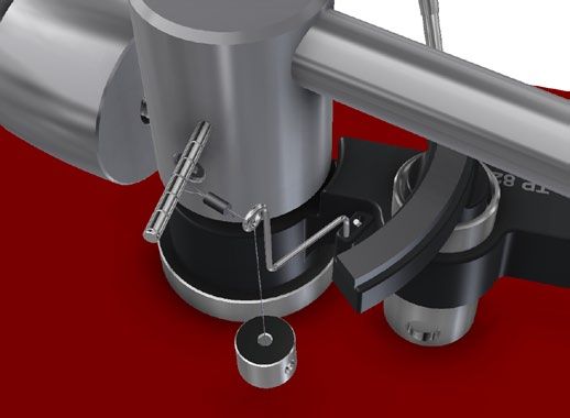
www.thorens.com
TD 203
Bedienungsanleitung
       User Manual
     Mode d’Emploi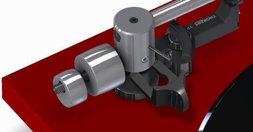
Inhalt

SICHERHEITSHINWEISE			           6
AUSPACKEN			                     7
AUFSTELLUNG UND MONTAGE          8
LAUFWERKSEINSTELLUNGEN          11
ANSCHLUSS                       12
TONARM UND TONABNEHMERSYSTEM    14
AUFLAGEKRAFT		                  15
AZIMUTH		                       16
ANTISKATINGKRAFT                17
WEITERE TONARMEINSTELLUNGEN     18
BETRIEB DES PLATTENSPIELERS		   19
TECHNISCHE DATEN				            20
SERVICEINFORMATIONEN			         21
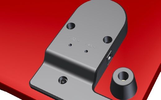
Table of Contents                    Sommaire

SAFETY INSTRUCTIONS			          22   CONSIGNES DE SECURITE		            38
UNPACKING			                    23   DEBALLAGE                          39
SETUP AND ASSEMBLY              24   INSTALLATION ET MONTAGE            40
TURNTABLE ADJUSTMENTS           27   REGLAGES DE L’ENTRAINEMENT         43
CONNECTIONS                     28   RACCORDEMENT                       44
TONEARM AND PICK-UP CARTRIDGE   30   BRAS ET CELLULE DE LECTURE         46
TRACKING FORCE		                31   FORCE D’APPUI		                    47
AZIMUTH                         32   AZIMUTH                            48
ANTI-SKATING FORCE (BIAS)       33   FORCE ANTISKATING                  49
FURTHER TONEARM ADJUSTMENTS     34   AUTRES REGLAGES DU BRAS            50
OPERATION		                     35   UTILISATION DE LA PLATINE		        51
TECHNICAL SPECIFICATIONS			     36   CARACTERISTIQUES TECHNIQUES		      52
CUSTOMER SERVICE			             37   INFORMATIONS SERVICE APRES-VENTE   53
Sicherheitshinweise

BITTE VOR DER ERSTMALIGEN INBETRIEBNAHME                                 Dieses Elektronikprodukt entspricht den gültigen Richtlini-
AUFMERKSAM LESEN!                                                        en zur Erlangung des CE-Zeichens. Alle notwendigen Prü-
                                                                         fungen wurden mit positivem Ergebnis vorgenommen.

VORSICHT                                                                 2002/95/EC (RoHS) konform.
Um einen elektrischen Schlag zu vermeiden, darf das Gehäuse nicht
geöffnet werden. Im Geräteinneren befinden sich keine vom Benutzer
zu wartenden Teile.                                                      WICHTIG: ENTSORGUNG VON ELEKTROGE-
                                                                         RÄTEN DURCH VERBRAUCHER IN PRIVATEN
                                                                         HAUSHALTEN INNERHALB DER EU
WARNUNG
                                                                         Dieses Symbol auf dem Produkt oder dessen Ver-
UM DER GEFAHR VON FEUER UND EINES ELEKTRISCHEN SCHLA-
                                                                         packung gibt an, dass dieses Produkt nicht zu-
GES VORZUBEUGEN, DARF DAS GERÄT WEDER REGEN NOCH                         sammen mit dem Restmüll entsorgt werden darf.
FEUCHTIGKEIT AUSGESETZT WERDEN.                                          Es obliegt daher Ihrer Verantwortung, das Gerät
                                                                         an einer entsprechenden Stelle für die Entsorgung
                                                                         oder Wiederverwertung von Elektrogeräten aller
                  ERLÄUTERUNG DER GRAFISCHEN SYMBOLE                     Art abzugeben (z.B. ein Werkstoffhof). Die separa-
                  Das Blitz-Symbol mit dem nach unten weisenden          te Sammlung und das Recyceln Ihrer alten Elekt-
                  Pfeil im gleichseitigen Dreieck warnt vor “gefährli-   rogeräte zum Zeitpunkt ihrer Entsorgung trägt zum
                  cher Spannung” im Gehäuseinneren, deren Höhe           Schutz der Umwelt bei und gewährleistet, dass sie
                  für eine Gefährdung von Personen durch einen           auf eine Art und Weise recycelt werden, die keine
                  Stromschlag ausreichend ist.                           Gefährdung für die Gesundheit von Mensch und
                                                                         Umwelt darstellt. Weitere Informationen darüber,
                  Das Ausrufezeichen innerhalb des gleichseitigen        wo Sie alte Elektrogeräte zum Recyceln abgeben
                  Dreiecks macht auf wichtige Bedienungs- und            können, erhalten Sie bei den örtlichen Behörden,
                  Wartungshinweise in der beiliegenden Bedie-            Werkstoffhöfen oder dort, wo Sie das Gerät erwor-
                  nungsanleitung aufmerksam.                             ben haben.

6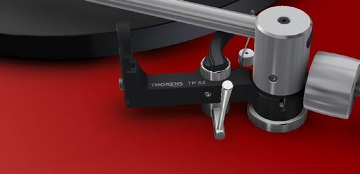
Auspacken

Nehmen Sie das Gerät und die mitgelieferten Einzelteile
vorsichtig aus der Verpackung und prüfen Sie den
Lieferumfang auf Vollständigkeit:

   1 x Chassis mit Subteller und Tonarm
   1 x Thorens Antriebsriemen
   1 x Plattenteller
   2 x Tonarmgegengewicht
   1 x Antiskatinggewicht mit Faden
   1 x Staubschutzhaube                                                                                   Abb. 1
   1 x Steckernetzteil mit Netzkabel
   1 x Adapter für 7” Schallplatten                       Entfernen Sie die Transportsicherung am Tonarm ➔ Abb. 1
   1 x Tonarmwaage
   1 x Einstellschablone                                     Bitte bewahren Sie die Verpackung und die Trans-
                                                             portsicherung auf, falls das Gerät einmal zum Trans-
                                                             port verpackt werden muss!

                                                                                                                   7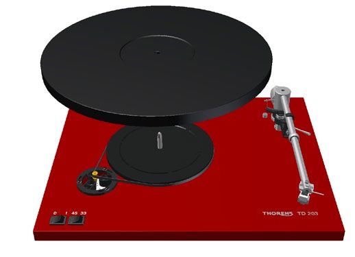
Aufstellung und Montage

Stellen Sie den Plattenspieler auf eine waagrechte und    Achten Sie bei der Aufstellung Ihres neuen Plattenspie-
stabile Unterlage.                                        lers darauf, einen Mindestabstand zu anderen elek-
                                                          tronischen Geräten (z.B. Verstärker, Reciever oder
Thorens Plattenspieler sind relativ unempfindlich ge-     CD-Spieler) einzuhalten, da es sonst zu magnetischen
genüber Erschütterungen. Dennoch stellen diese            Einstrahlungen auf das Tonabnehmersystem kommen
ein generelles Problem bei der Plattenwiedergabe mit      kann, welche sich durch Brummstörungen in der Wie-
hochwertigen Tonabnehmern dar. Wählen Sie deshalb         dergabe äußern. Dies gilt auch für das Anschlusskabel,
ein möglichst stabiles Möbelstück zur Aufstellung und     dass den Plattenspieler mit dem Verstärker verbindet.
vermeiden Sie die Nähe zu Lautsprechern.
                                                             Magnetische Störungen kann man leicht ermitteln
Leider reicht dies in älteren Häusern mit Holzbalken-        und beseitigen, indem man Aufstellung und Position
decken bisweilen nicht aus. In der Regel hilft hier al-      der Geräte zueinander verändert.
lerdings die Aufstellung des Plattenspielers auf einer
Konsole, die mit geeigneten Konsolenträgern an einer
tragenden Zimmerwand befestigt wird.

8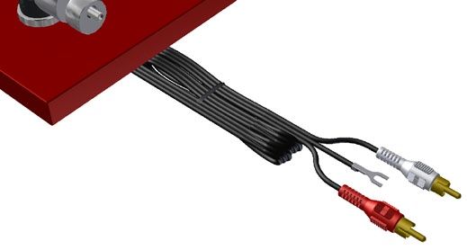
Aufstellung und Montage

Legen Sie den Antriebsriemen um den Subteller und
die Riemenscheibe des Motors. ➔ Abb. 2

   Vermeiden Sie Öl- oder Fettspuren auf Antriebsrie-
   men, Riemenscheibe und Subteller.

Die Riemenspannung ist von Werk aus korrekt ein-
gestellt. Bei Bedarf (z.B. um alterungsbedingte Span-
nungsverluste des Riemens auszugleichen) kann diese
nachjustiert werden. Lösen Sie hierzu die drei Schrau-
ben der exzentrischen Motorenhalterung und verdre-
hen sie diese feinfühlig. ➔ Abb. 2

Wenn die Riemenspannung verändert wurde, muss die
Drehzahl neu eingestellt werden. ➔ Seite 11               Abb. 2

   Sie sollten den Antriebsriemen nach einigen Jahren
   ersetzen. Original Thorens Ersatzriemen erhalten Sie
   bei allen Thorens Händlern oder Vertrieben.

                                                                   9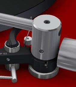
Aufstellung und Montage
Platzieren Sie den Plattenteller auf dem Subteller.
➔ Abb. 3
Der Plattenspieler ist nun beinahe vollständig montiert,
Sie müssen nur noch die Tonarmgewichte und das An-
tiskatinggewicht am Tonarm anbringen. ➔ Seite 14
Abb. 3
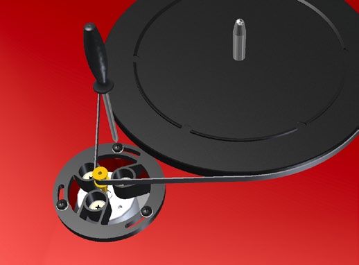
10Laufwerkseinstellungen
Eine Justage der Drehzahl kann mithilfe der Einstell-
schrauben auf der Unterseite der Motorabdeckung Abb. 4
vorgenommen werden. ➔ Abb. 4
Die Drehzahlen sind ab Werk voreingestellt. Jede
Änderung sollte mithilfe einer Meßschallplatte oder
33
einer stroboskopischen Meßeinrichtung kontrolliert 45
werden.
Siehe hierzu auch „Riemenspannung“ ➔ Seite 9
11Anschluss
Dem Plattenspieler liegt ein Universalsteckernetzteil
bei, welches an allen gängigen Netzspannungen ver- Abb. 5
wendet werden kann.
Verbinden Sie zunächst den Niederspannungsstecker
des Steckernetzteils mit der entsprechenden Buch-
se am Plattenspieler und stecken Sie das Netzteil an-
schließend in die Netzsteckdose. ➔ Abb. 5
Um den Plattenspieler an anderen Netzspannungen
als der angegebenen zu betreiben, benötigen Sie
ggf. einen Adapter für den Netzstecker. Ihr Thorens
Händler oder Vertrieb hilft Ihnen gerne weiter.
12Anschluss
Verbinden Sie das Cinchkabel des Plattenspielers mit Abb. 6
dem (Phono-)Eingang Ihres Verstärkers. Achten Sie
hierbei auf die richtige Polung der Anschlüsse. ➔ Abb. 6
Schallplatten sind nach RIAA-Norm verzerrt aufge-
nomen, Plattenspieler benötigen daher immer einen
speziellen Entzerrvorverstärker. Sofern Ihr Verstärker
über keinen Phono-Eingang verfügt, müssen Sie ei-
nen zusätzlichen Phonovorverstärker (z.B. Thorens
MM-Serie) zwischen Plattenspieler und Verstärker
schalten. Ihr Thorens Händler oder Vertrieb hilft Ih-
nen gerne weiter.
Ein Brummgeräusch in den Lautsprechern, dessen
Die integrierte Erdungslitze (➔ Abb. 6) stellt die Erd- Laustärke sich mit dem Lautstärkeregler beeinflus-
bzw. Masseverbindung her. Verbinden Sie diese mit der sen lässt, kann ein Zeichen für eine fehlerhafte Erd-
Masseschraube am Verstärker. Besitzt Ihr Verstärker verbindung sein. Zunächst sollte untersucht werden,
keine Masseschraube, so können Sie das Kabel auch ob die Masseverbindung einen sicheren Kontakt auf-
am Außenrand einer nicht verwendeten Eingangsbuch- weist und die Litze ggf. an einer anderen Stelle be-
se anklemmen. festigt werden.
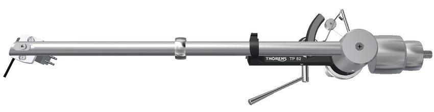
13Tonarm und Tonabnehmersystem
Ihr neuer Plattenspieler wird mit vorinstalliertem Tonarm Am Tonarm TP 82 können Tonabnehmer mit einem Ab-
TP 82 und dem Tonabnehmersystem TAS 257 (MM) ge- stand der Befestigungslöcher von 12,7 mm (½ ”) mon-
liefert. ➔ Abb. 7 tiert werden. Zum Anschluss des Tonabnehmersystems
werden die vier farblich gekennzeichneten Anschlußlit-
Die Tonarmgewichte sind zum Transport entfernt. Dre- zen auf die entsprechenden Anschluß-Stifte des Tonab-
hen Sie diese zur Montage von hinten auf den Tonarm. nehmers geschoben.
Das kleinere exzentrische Gewicht sollte sich stets so
nah wie möglich hinter dem großen Gewicht befinden, Verbinden Sie nach folgendem Schema, falls der Ton-
ohne dieses jedoch zu berühren. Stellen Sie anschlie- abnehmer keine Farbkennung aufweist:
ßend Auflagekraft und Azimuth ein. ➔ Seite 15/16
R rechter Kanal (Signal) ➔ rot
Das Antiskatinggewicht ist ebenfalls zum Transport G rechter Kanal (Masse) ➔ grün
entfernt und muss zur Montage am Tonarm eingehängt L linker Kanal (Signal) ➔ weiß
werden. ➔ Seite 17 G linker Kanal (Masse) ➔ blau
Abb. 7
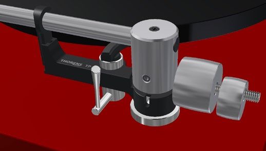
14Auflagekraft
Die Einstellung der Auflagekraft erfolgt durch drehen
der Tonarmgewichte (➔ Abb. 8). Je weiter die Gewich-
te nach vorne zum Tonabnehmer hin gedreht werden,
desto größer wird die Auflagekraft. Das kleinere, ex-
zentrische Gewicht dient der Einstellung des Azimuths
(➔ Seite 16). Es sollte sich so nah wie möglich hinter dem
größeren Gewicht befinden, ohne dieses zu berühren.
Die korrekte Auflagekraft können Sie mit Hilfe der Ton-
armwaage einstellen. Schwenken Sie hierzu den Ton-
arm bei abgesenktem Tonarmlift über den Plattenteller
Abb. 8
und senken Sie ihn vorsichtig ab, so dass die Nadel auf
der Tonarmwaage aufliegt. Entfernen Sie dabei unbe-
dingt die Schutzhaube des Tonabnehmers. Das in der Mitte des Tonarmrohres angebrachte
Ringgewicht (➔ Seite 14, Abb. 7) darf nicht verschoben
Gehen Sie äußerst vorsichtig vor, um die Nadel des werden. Es handelt sich um einen Resonanzdämp-
Tonabnehmers nicht zu beschädigen! fer, der nur exakt an dieser Position wirksam ist!
Der empfohlene Wert der Auflagekraft für die Kombi-
nation TP 82 / TAS 257 (MM) beträgt 23 mN (entspricht
einem Auflagegewicht von 2,3 g).
15Azimuth
Zur Einstellung des Azimuths muss das kleinere, ex-
zentrische Tonarmgewicht gedreht werden. ➔ Abb. 9
Der Azimuth ist korrekt eingestellt, wenn das Tonabneh-
mersystem exakt senkrecht zur Plattentelleroberfläche
steht. ➔ Abb. 10
90°
Abb. 9 Abb. 10
16Antiskatingkraft
Durch Zusammenwirken der Reibungskraft der Platten-
rillen mit den Lagerkräften am Tonabnehmer wird beim
Abspielen einer Schallplatte eine Kraftkomponente er-
zeugt, die den Tonarm nach innen zieht: Die Skating-
kraft. Zu ihrer Kompensation dient die Antiskatingkraft,
welche beim Tonarm TP 82 durch ein Gewicht erzeugt
wird.
Der Faden des Antiskatinggewichts wird durch die
Öse am Tonarm geführt und am Einhängestift des Ton-
arms eingehängt (➔ Abb. 11).
Am Einhängestift befinden sich sechs Rillen zum Ein-
hängen des Gewichts. Je weiter außen das Gewicht
eingehängt wird, desto größer ist die Antiskatingkraft. Abb. 11
Die benötigte Antiskatingkraft ist vom verwendeten Ton-
abnehmer und der Auflagekraft abhängig. Beim vorin- Die benötigte Antiskatingkraft ist vom verwendeten
stallierten Tonabnehmer TAS 257 (MM) sollte das Ge- Tonabnehmer abhängig und sollte bei einem Wech-
wicht in der 3. oder 4. Rille positioniert werden. sel mithilfe einer Meßschallplatte ermittelt werden.
17Weitere Tonarmeinstellungen
Bei einem Wechsel des Tonabnehmers kann der Über-
hang am Headshell um ± 2,5 mm angepasst werden.
Lösen Sie hierzu die Schraube oberhalb des Headshells
(➔ Abb. 12) und verschieben Sie dieses entsprechend.
Am hinteren Ende des Tonarmrohrs kann der Überhang
um weitere + 2,5 mm angepasst werden. Lösen Sie hier-
zu die Schraube oben am Lagerblock leicht mit maxi-
mal ein oder zwei Umdrehungen und verschieben Sie
das Tonarmrohr. ➔ Abb. 13
Abb. 12 Abb. 13
Die Schraube oben am Lagerblock darf keinesfalls
zu stark gelöst oder ganz entfernt werden, da hierbei
der Tonarm beschädigt werden kann!
Die Schrauben dürfen nach der Anpassung nicht zu
sehr festgezogen werden!
18Betrieb des Plattenspielers
Der Schalter zum Ein-/Ausschalten des Laufwerks
befindet sich links vorne auf der Oberseite des Plat-
tenspielers. Daneben befindet sich der Schalter zur
Geschwindigkeitsauswahl. Es stehen zwei Geschwin-
digkeiten zur Verfügung, 33 ⅓ (Langspielplatten) und 45
U/min (kleine Schallplatten bzw. Singles). ➔ Abb. 14
Zum Abspielen einer Platte wird der Plattenspieler
zunächst mit der entsprechenden Geschwindigkeit
Abb. 14
gestartet. Dann wird der Tonarmlift (➔ Abb. 15) angeho-
ben, hierzu muss der Hebel nach hinten oben bewegt
werden. Nun wird der Tonabnehmer über der Einlaufril-
le oder über dem gewünschten Stück positioniert und
anschließend mithilfe des Lifts auf die Platte abgesenkt.
Der Plattenspieler besitzt keine automatische Endab-
schaltung. Sobald die Auslaufrille erreicht ist, muss der
Tonarm mittels Handlift von der Platte gehoben und der
Plattenspieler manuell abgeschaltet werden.
Abb. 15
19Technische Daten
TD 203
Funktion manuell
Antrieb Flachriemen (innenliegend)
Motor elektronisch gesteuerter DC-Motor
Geschwindigkeiten 33 ⅓, 45 U/min
Einstellbereich ±5 %
Geschw.umschaltung elektronisch
Plattenteller 12” / 0,8 kg (ABS)
Stromversorgung Steckernetzteil 12 V DC
Abmessungen 400 x 92,6 x 320 mm (B x H x T; ohne Staubschutzhaube)
Gewicht 3,53 kg (ohne Staubschutzhaube)
Tonarm Thorens TP 82
Effektive Länge 232,8 mm (9,1”)
Überhang 17,8 mm (variabel)
Kröpfungswinkel 23,6° (fest)
Dynamische Masse ca. 11 g
Technische Änderungen vorbehalten.
20Serviceinformationen
Bei Fragen zu Ihrem neuen Plattenspieler oder bei
Problemen steht Ihnen Ihr Thorens Fachhändler
oder Vertrieb gerne zur Verfügung. Ihren Thorens Ver-
triebspartner finden Sie auf ➔ www.thorens.de oder Sie
kontaktieren uns direkt:
➔ www.thorens.de/kontakt
Registrieren Sie Ihr Produkt bei Thorens und erhal-
ten Sie regelmäßig aktuelle Informationen und exklusive
Angebote von Thorens. Verwenden Sie hierzu die bei-
liegende Registrierungskarte oder registrieren Sie Ihr
Produkt online:
➔ www.thorens.de/registrierung
21Safety instructions
PLEASE READ THIS PAGE CAREFULLY BEFORE
OPERATING YOUR UNIT!
This product was tested and complies with all the
requirements for the CE Mark.
CAUTION
To reduce risk of electric shock, do not remove the cover (or back). Compliant to 2002/95/EC (RoHS)
No user-serviceable parts inside.
WARNING IMPORTANT: DISPOSAL OF WASTE EQUIP-
MENT BY USERS IN PRIVATE HOUSEHOLDS
TO PREVENT FIRE OR SHOCK HAZARD, DO NOT EXPOSE THIS
IN THE EUROPEAN UNION
APPLIANCE TO RAIN OR MOISTURE.
This symbol on the product or on its packaging in-
dicates that this product must not be disposed off
with your other household waste. Instead, it is your
EXPLANATION OF GRAPHICAL SYMBOLS responsibility to dispose of your waste equipment by
handing it over to a designated collection point for
The lightning flash with arrowhead symbol, within the recycling of waste electrical and electronic equip-
an equilateral triangle, is intended to alert you to ment. The separate collection and recycling of your
the presence of uninsulated ‘dangerous voltage’ waste equipment at the time of disposal will help to
within the product’s enclosure that may be of suf- conserve natural resources and ensure that it is re-
ficient magnitude to constitute an electric shock to cycled in a manner that protects human health and
persons. the environment. For more information about where
The exclamation point within an equilateral triangle you can drop off your waste equipment for recycling,
is intended to alert you to the presence of important please contact your local city office, your household
operating and maintenance (servicing) instructions in waste disposal service or the shop where you pur-
the literature accompanying the appliance. chased the product.
22Unpacking
Carefully remove the turntable and all accessories from
the box. Check that the following items are included:
1 x plinth with sub-platter and tonearm
1 x Thorens drive belt
1 x platter
2 x tonearm counterweight
1 x bias weight with string
1 x dust cover
1 x plug-in power supply and power cable
1 x adapter for 7-inch records
Fig. 1
1 x stylus gauge
1 x cartridge alignment protractor Remove the tonearm transport lock. ➔ Fig. 1
Please keep the packaging and the transport lock
for future transport. Always replace the transport lock
before re-packing and shipping.
23Setup and Assembly
Place the turntable on a straight, stable surface. When siting the turntable, make sure that it is at a rea-
sonable distance from any existing electronic equip-
Thorens turntables are relatively resistant to vibration. ment (such as amplifiers, receivers or CD players) so
However, vibration can have adverse effects on any as to avoid electromagnetic interference in the pick-up
turntable, particularly if a high-quality pick-up cartridge cartridge, which could cause a hum in the signal. The
is used. You should therefore place the turntable on a same applies to the cable connecting the turntable to
sturdy piece of furniture, ideally at some distance from the amplifier.
the loudspeakers.
You can detect and eliminate electromagnetic inter-
older houses with beam floors, however, this may not be ference by changing the position of the turntable with
enough to properly isolate the turntable from vibrations. respect to other pieces of equipment.
In this case we recommend placing the turntable on a
wall shelf that is attached to a supporting wall.
24Setup and Assembly
Loop the drive belt around the sub-platter and then
around the motor pulley. ➔ Fig. 2
Avoid oil or grease coming into contact with the belt,
pulley or sub-platter. If necessary, these parts can be
cleaned with glass cleaner or pure alcohol and a lint-
free cloth.
The belt tension is factory-adjusted. If it needs to be re-
adjusted (e.g. to compensate for gradual belt stretch),
loosen the three locking screws of the eccentric motor
support ring and carefully rotate the ring. ➔ Fig. 2
If the belt tension is changed, the platter speed will
need to be reset. ➔ Page 27 Fig. 2
The drive belt should be replaced every few years.
Thorens replacement belts are available from any
Thorens dealer or distributor.
25Setup and Assembly
Place the platter onto the sub-platter. ➔ Fig. 3
This almost completes the assembly of the turntable.
Fitting the tonearm counterweights and the bias weight
to the tonearm will complete the assembly of the turnta-
ble. ➔ Page 30
Fig. 3
26Turntable adjustments
The platter speed can be adjusted by turning the
adjustment screws on the bottom of the motor cover. Fig. 4
➔ Fig. 4
The platter speeds are factory-adjusted. Any readjust-
ment of the speeds should be checked with the help
33
of a test record or a strobe disc. 45
Please also refer to “Belt Tension” ➔ Page 25
27Connections
The turntable comes with a universal plug-in power
supply that will accommodate all common mains volt- Fig. 5
ages.
Plug the low-voltage connector of the power supply into
the appropriate socket on the turntable and then plug
the power supply into the mains socket. ➔ Fig. 5
If the turntable is to be powered by mains voltages
other than those specified, it may be necessary to
use an adapter. Please contact your Thorens dealer
or distributor for further advice.
28Connections
Connect the turntable’s RCA phono cable to the phono Fig. 6
input of your amplifier. Check that the plugs are con-
nected with the correct polarity. ➔ Fig. 6
In accordance with RIAA standards, vinyl records are
cut with pre-emphasis. The operation of a turntable
therefore requires the use of a phono stage for equal-
isation. If your amplifier does not have a phono input,
you will need to connect a dedicated phono stage
(such as the Thorens MM series phono stages) be-
tween the turntable and the amplifier. Please contact
your Thorens dealer or distributor for further advice.
The integrated earth wire is used to establish an elec- If you can hear a hum in the speakers that increases
trical connection to earth. Connect the wire to the earth as you increase the overall volume, then the earth
screw on the amplifier. If your amplifier does not have connection may be faulty. Make sure that the earth
an earth screw, you can attach the wire to the side of an wire is firmly connected. If the problem persists, try
unused input socket. connecting the wire to a different spot.
29Tonearm and Pick-Up Cartridge
Your Thorens turntable is delivered with a pre-installed The TP 82 tonearm can accommodate most pick-up
TP 82 tonearm and an TAS 257 (MM) pick-up cartridge. cartridges with a distance of 12.7 mm (½ ”) between the
➔ Fig. 7 mounting holes. To connect the pick-up cartridge, push
the four colour-coded cartridge tags onto the cartridge
The tonearm counterweights are removed for ship- pins.
ping. Screw the large counterweight onto the rear sec-
tion of the tonearm, then the smaller, eccentric weight. If the cartridge pins are not colour-coded, connect them
The smaller weight should always sit as close as pos- as follows:
sible to the large weight without touching it. Adjust the
tracking force and the azimuth. ➔ Page 31/32 R right channel (signal) ➔ red
G right channel (earth) ➔ green
The bias weight is also removed for shipping and L left channel (signal) ➔ white
needs to be fitted to the tonearm. ➔ Page 33 G left channel (earth) ➔ blue
Fig. 7
30Tracking Force
The tracking force can be adjusted by rotating the to-
nearm counterweights (➔ Fig. 8). The closer the coun-
terweights are to the pick-up cartridge, the higher the
tracking force. The smaller, eccentric weight is used to
adjust the azimuth (➔ Page 32). It should sit as close as
possible to the large weight without touching it.
The correct tracking force can be set with the help of
the stylus gauge. Lower the tonearm lift, move the to-
nearm out over the platter and carefully lower it until the
stylus of the pick-up cartridge comes to rest on the sty-
Fig. 8
lus gauge. The stylus guard must be removed for this
procedure.
Do not move the ring that sits around the middle of
Great care should be taken to avoid damaging the the tonearm tube (➔ Page 30, Fig. 7). It serves as a vi-
stylus. bration damper and is effective only at its original
position.
The recommended tracking force for the TP 82/TAS
257 (MM) combination is 23 mN (2.3 g).
31Azimuth
To adjust the azimuth, rotate the smaller, eccentric
counterweight. ➔ Fig. 9
The azimuth setting is correct when the pick-up car-
tridge is exactly perpendicular to the platter surface.
➔ Fig. 10
90°
Fig. 9 Fig. 10
32Anti-Skating Force (Bias)
The interaction of stylus friction and cartridge bearing
forces produces a force which pulls the tonearm to-
wards the centre of the record (referred to as skating
force). This force can be offset with the help of anti-skat-
ing force, which, in the case of the TP 82, is produced
by a bias weight.
Lead the bias weight string through the hanger guide
and hook the string’s loop over the tonearm’s bias shaft
(➔ Fig. 11).
The string can be located in one of six grooves on the
bias shaft. The further out the string loop on the bias
shaft, the higher the anti-skating force. The amount of
anti-skating force required depends on the type of pick- Fig. 11
up cartridge and the tracking force used. With the pre-
installed TAS 257 (MM) cartridge, locate the string loop The amount of anti-skating force required depends
on the third or fourth groove. on the type of pick-up cartridge used. If you change
the cartridge for a different type, use a test record
to determine how much anti-skating force is required.
33Further Tonearm Adjustments
The tonearm headshell allows an overhang adjustment
of ±2.5 mm to be made, which may be necessary when
installing a new pick-up cartridge. To adjust overhang,
loosen the screw holding the headshell and move the
headshell as required. ➔ Fig. 12
Overhang can be further adjusted by +2.5 mm at the
rear of the tonearm. To do so, loosen the screw at the
top of the bearing housing by one or two turns at most
and move the tonearm tube as required. ➔ Fig. 13
Fig. 12 Fig. 13
The screw at the top of the bearing housing must not
be loosened too far, let alone removed completely,
as this may result in damage to the tonearm!
Take care not to over-tighten the screws after making
adjustments.
34Operation
The on/off and speed selector switches are located at
the front left-hand corner of the turntable plinth. There
are two speeds: There are two speeds: 33 ⅓ rpm (for
LPs) and 45 rpm (for singles). ➔ Fig. 14
To play a record, first start the turntable by selecting
the appropriate speed. Then engage the tonearm lift
(➔ Fig. 15) by lifting its lever, position the pick-up car-
tridge over the run-in groove or the desired track and
Fig. 14
lower the tonearm lift.
The turntable does not feature an automatic shut-
off mechanism. Therefore, as soon as the stylus has
reached the run-out groove, engage the tonearm lift and
switch the turntable off.
Fig. 15
35Technical Specifications
TD 203
Mode of operation Manual
Drive system Belt drive (flat belt around sub-platter)
Motor Servo-controlled DC motor
Speeds 33 ⅓, 45 rpm
Adjustment range ±5 %
Speed change Electronic
Platter 12” / 0.8 kg (ABS)
Power supply External plug-in power supply 12 V DC
Dimensions 400 x 92,6 x 320 mm (W x H x D; without dust cover)
Weight 3.53 kg (without dust cover)
Tonearm Thorens TP 82
Effective length 232.8 mm (9.1”)
Overhang 17.8 mm (variable)
Offset angle 23.6° (fixed)
Effective mass approx. 11 g
Technical specifications subject to change without notice.
36Customer Service
Your Thorens dealer or distributor will be happy to as-
sist you if you have any questions regarding your new
turntable or experience any problems. For a list of Tho-
rens distributors, please visit ➔ www.thorens.com or
contact us directly:
➔ www.thorens.com/contact
Register your product with Thorens to receive up-to-
date information and special offers. You can use the
registration card included with the product or visit our
website:
➔ www.thorens.com/register
37Consignes de sécurité
A LIRE ATTENTIVEMENT AVANT LA PREMIERE MISE Ce produit électronique est conforme aux directives euro-
EN SERVICE ! péennes pour l‘obtention de la marque CE. Tous les essais
nécessaires ont été effectués avec un résultat positif.
ATTENTION Conforme 2002/95/EC (RoHS).
Le Le châssis de l’appareil ne doit pas être ouvert, afin d’éviter tout
choc électrique. Auaucune pièce nécessitant un entretien de la part
de l’utilisateur ne se trouve à l’intérieur de l’appareil. IMPORTANT : ELIMINATION D‘APPAREILS
ELECTRIQUES PAR LES UTILISATEURS PAR-
TICULIERS RESIDANT DANS LA CE
AVERTISSEMENT
Ce symbole, figurant sur le produit ou sur son em-
POUR EVITER TOUT DANGER D’INCENDIE ET DE CHOC ELECTRI-
ballage, indique que ce produit ne doit pas être
QUE, L’APPAREIL NE DOIT PAS ETRE EXPOSE A LA PLUIE ET A éliminé avec les ordures ménagères. Il est de votre
L’HUMIDITE. responsabilité de remettre ce produit à une entre-
prise d’élimination ou de recyclage d’appareils
électriques de tous types (par ex. une décharge
EXPLICATION DES SYMBOLES GRAPHIQUES spécialisée). La collecte sélective et la réutilisa-
Le symbole éclair avec flèche vers le bas dans tion de tous vos anciens appareils électroniques à
le triangle avertit d’une « tension dangereuse » à l’occasion de leur élimination, contribuent à la pro-
l’intérieur de l’appareil, dont le niveau est suffisant tection de l’environnement et assurent qu’ils soient
pour présenter un danger de choc électrique aux recyclés de manière à éviter de porter atteinte à
personnes. la santé humaine et à la protection de la nature.
Pour obtenir de plus amples informations sur les
Le point d’exclamation à l’intérieur du triangle indi- dépôts et le recyclage des appareils électroniques
que des instructions de commande et d’entretien usagés, adressez-vous aux autorités locales, aux
figurant dans le présent mode d’emploi. déchèteries ou au distributeur qui vous a vendu
l’appareil.
38Déballage
Sortez avec précaution l’appareil et les pièces déta-
chées livrées de l’emballage et vérifiez le contenu de
la livraison :
1 x châssis avec plateau inférieur et bras de lecture
1 x courroie d’entraînement Thorens
1 x plateau
2 x contrepoids du bras de lecture
1 x poids antiskating avec fil
1 x capot anti-poussière Fig. 1
1 x bloc d’alimentation avec cordon secteur
1 x adaptateur pour disques 7” Retirez le verrou de transport du bras de lecture. ➔ Fig. 1
1 x jauge de réglage du bras de lecture
1 x rapporteur (gabarit) d’alignement de la cellule Veuillez garder l’emballage et le verrou de transport
pour tout transport futur de l’appareil. Replacez tou-
jours le verrou de transport avant le ré-emballage et
l’expédition.
39Installation et montage
Placez la platine sur une surface stable et plane. Lors de l’installation de votre nouvelle platine, veillez
à respecter une distance suffisante par rapport aux
Les platines Thorens sont relativement insensibles aux autres appareils électroniques (par ex. amplificateurs,
vibrations. Cependant, il pourrait y avoir un problème récepteurs ou lecteurs de CD), car il pourrait y avoir
dans le cas de lecture de disques avec une cellule de des rayonnements électromagnétiques sur la cellule de
lecture de très haute sensibilité. C’est pourquoi nous lecture qui provoquent des bourdonnements dans la
vous recommandons d’installer la platine sur un meuble reproduction sonore. Ceci est également valable pour
très stable et d’éviter la proximité des haut-parleurs. le câble de raccordement, qui relie la platine à l’ampli-
ficateur.
Il arrive que ces précautions soient insuffisantes dans
des maisons anciennes avec des planchers à poutres. On peut facilement détecter et éliminer les perturba-
En principe, on peut alors résoudre le problème en pla- tions électromagnétiques, en changeant la position
çant la platine sur une étagère murale qui devra être de la platine par rapport aux autres appareils lors de
fixée avec des supports appropriés à un mur porteur. l’installation.
40Installation et montage
Posez la courroie d’entraînement autour du plateau
inférieur, puis autour de la poulie du moteur. ➔ Fig. 2
Evitez les traces d’huile ou de graisse sur la courroie
d’entraînement, la poulie ou le plateau inférieur.
La tension de la courroie est correctement réglée en
usine. En cas de besoin (par ex. pour compenser la
perte de tension due au vieillissement de la courroie)
elle peut être ajustée. Pour ce faire, desserrez les trois
vis de blocage de l’anneau de support excentrique du
moteur et tournez délicatement. ➔ Fig. 2
Si la tension de la courroie est modifiée, il faut régler à
nouveau la vitesse de rotation. ➔ Page 43 Fig. 2
Après quelques années, Il est recommandé de rem-
placer la courroie d’entraînement. Vous trouverez des
courroies originales Thorens chez tous les distribu-
teurs Thorens.
41Installation et montage
Placez le plateau sur le plateau inférieur. ➔ Fig. 3
L’assemblage de la platine est pratiquement achevé. Il
ne reste qu’à monter les contrepoids et le poids antiska-
ting sur le bras de lecture. ➔ Page 46
Fig. 3
42Réglages de l’entraînement
La vitesse de rotation peut être réglée à l’aide des
vis de réglage situées sur le dessous du couvercle du Fig. 4
moteur. ➔ Fig. 4
Les vitesses de rotation sont préréglées en usine.
Chaque modification de vitesse devra être vérifiée à
33
l’aide d’un disque de test ou un appareil de mesure 45
stroboscopique.
Voir également «Tension de la courroie» ➔ Page 41
43Raccordement
La platine est livrée avec un bloc secteur universel,
qui peut être utilisé avec toutes les tensions secteur Fig. 5
courantes.
Insérez d’abord la fiche basse tension du bloc secteur
dans la prise correspondante de la platine et insérez
ensuite le bloc secteur dans la prise secteur. ➔ Fig. 5
Pour utiliser la platine avec d’autres tensions que
celles indiquées vous devrez éventuellement utiliser
un adaptateur pour la prise secteur. Votre revendeur
ou distributeur Thorens est à votre disposition pour
plus de renseignement.
44Raccordement
Raccordez le câble RCA phono de la platine à l’entrée Fig. 6
phono de votre amplificateur. Veillez à la bonne polarité
des raccordements. ➔ Fig. 6
Les disques sont enregistrés avec une distorsion
conforme à la norme RIAA, les platines ont donc tou-
jours besoin d’un préamplificateur spécial redresseur
de distorsion. Si votre amplificateur ne dispose pas
d’une entrée phono, vous devrez connecter un pré-
amplificateur phono supplémentaire (comme les pré-
amplificateurs phono Thorens de la série MM) entre
la platine et l’amplificateur. Adressez-vous à votre
revendeur ou distributeur Thorens.
Un bourdonnement des haut-parleurs, dont le niveau
La tresse de mise à la terre réalise la liaison de terre peut être réglé par le bouton de volume, peut être
ou de masse. Reliez-la à la vis de mise à la terre sur le signe d’une mise à la terre défectueuse. Vérifiez
l’amplificateur. Si votre amplificateur ne possède pas de d’abord si le contact de la liaison de masse est cor-
vis de mise à la terre, vous pouvez aussi la raccorder rect et si le problème persiste, déplacez le point de
sur le bord extérieur d’une prise d’entrée non utilisée. contact de la tresse de masse à un autre endroit.
45Bras et cellule de lecture
Votre platine Thorens est livrée avec un bras de lecture La plupart des cellules de lecture ayant un écartement
TP 82 et une cellule de lecture TAS 257 (MM) pré-ins- des trous de fixation de 12,7 mm (½ ”) peuvent être
tallés. ➔ Fig. 7 montées sur le bras de lecture TP 82. Pour raccorder
la cellule de lecture, placez les quatre cosses repérées
Les contrepoids du bras de lecture sont retirés pour par couleur de la cellule sur les picots de la cellule.
l’expédition. Vissez le grand contrepoids sur la partie
arrière du bras de lecture, puis le poids excentrique, Procédez au raccordement selon le schéma suivant si
plus petit. Le poids le plus petit doit toujours être situé le la cellule n’a pas de repère couleur :
plus près possible du grand poids sans toucher celui-
ci. Ajustez la force d’appui et l’azimut. ➔ Page 47/48 R Canal droit (signal) ➔ rouge
G Canal droit (masse) ➔ vert
Le poids antiskating est aussi retiré pour l’expédition et L Canal gauche (signal) ➔ blanc
doit être monté sur le bras de lecture. ➔ Page 49 G Canal gauche (masse) ➔ bleu
Fig. 7
46Force d’appui
La force d’appui se règle par la rotation des contre-
poids du bras de lecture (➔ Fig. 8). Plus les contrepoids
sont rapprochés de la cellule de lecture, plus la force
d’appui est élevée. Le poids excentrique plus petit est
utilisé pour régler l’azimut (➔ Page 48). Il doit être situé le
plus près possible du plus grand contrepoids sans le
toucher.
Vous pouvez régler la force d’appui correcte à l’aide
de la jauge de réglage du bras de lecture. Abaissez le
lève-bras et déplacez le bras au dessus du plateau et
Fig. 8
abaissez-le prudemment afin que l’aiguille repose sur
la jauge. La protection de l’aiguille de lecture doit être
retirée pour cette procédure. La bague montée au milieu du tube du bras de lec-
ture (➔ Page 46, Fig. 7) ne doit pas être déplacée. Il
Procédez avec une extrême précaution, pour ne pas s’agit d’un amortisseur de résonance, qui n’est effi-
endommager l’aiguille de la cellule de lecture ! cace que dans cette position !
La force d’appui recommandée pour la combinaison
TP 82/TAS 257 (MM) est 23 mN (2,3 g).
47Azimuth
La rotation du poids excentrique plus petit permet de
régler l’azimut. ➔ Fig. 9
Le réglage de l’azimut est correct quand la cellule de
lecture est exactement perpendiculaire à la surface du
plateau. ➔ Fig. 10
90°
Fig. 9 Fig. 10
48Force antiskating
Un effet combiné de la force de frottement des sillons
du disque et des forces du palier du bras génère lors
de la lecture du disque une composante de forces, qui
tire le bras de lecture vers le centre : la force skating. La
force antiskating qui sert à la compenser est produite,
dans le cas du TP 82, par un poids antiskating.
Guidez le fil du poids antiskating à travers l’étrier et ac-
crochez la boucle du fil à la tige antiskating du bras de
lecture (➔ Fig. 11).
Le fil peut être situé sur une des six rainures de la tige
antiskating. Plus la boucle du fil sur la tige est éloignée
du bras de lecture, plus la force antiskating est élevée.
La force antiskating nécessaire dépend du type de cel- Fig. 11
lule de lecture et de la force d’appui utilisée. Avec la
cellule pré-installée TAS 257 (MM), la boucle du fil doit La force antiskating nécessaire dépend du type de
être située sur la troisième ou la quatrième rainure. cellule de lecture et devrait être définie à l’aide d’un
disque de mesure en cas de remplacement.
49Autres réglages du bras de lecture Lors du remplacement de la cellule, le porte-cellule permet un réglage du porte-à-faux (overhang) de ±2.5 mm, si nécessaire. Desserrez pour cela la vis retenant le porte-cellule et déplacez celui-ci en conséquence. ➔ Fig. 12 Vous pouvez ajuster le porte-à-faux de +2,5 mm sup- plémentaires à l’extrêmité arrière du bras de lecture. Pour ce faire, desserrez la vis située sur le dessus du palier d’un ou deux tours au plus et déplacez le tube du bras de lecture au besoin. ➔ Fig. 13 Fig. 12 Fig. 13 La vis située sur le dessus du palier ne doit pas être trop desserrée, ni même complètement retirée, car cela risque d’endommager le bras de lecture ! Une fois le réglage terminé, ne pas serrer trop forte- ment les vis ! 50
Utilisation de la platine

Les commutateurs marche/arrêt et le sélecteur de
vitesse se trouvent dans le coin avant gauche sur le
châssis de la platine. Vous disposez de deux vitesses
de rotation, 33⅓ (disque longue durée) et 45 t/mn
(disque petit diamètre ou single). ➔ Fig. 14

Pour la lecture d’un disque, sélectionnez d’abord la
vitesse appropriée. Puis levez le bras de lecture (➔ Fig.
15) en actionnant son levier vers le haut. Déplacez en-
                                                              Fig. 14
suite la cellule de lecture au-dessus du sillon d’entrée
ou au-dessus du morceau souhaité et abaissez-la sur le
disque à l’aide du lève-bras.

La platine n’est pas équipée d’un arrêt automatique.
Dès que le sillon de fin de disque est atteint, soulevez le
bras de lecture à l’aide du lève-bras et arrêtez manuel-
lement la platine.

                                                              Fig. 15

                                                                   51
Caractéristiques techniques
TD 203
Fonctionnement manuel
Entraînement courroie plate (intérieure)
Moteur moteur DC à commande électronique
Vitesses de rotation 33 ⅓, 45 t/mn
Plage de réglage ±5 %
Commutation vitesse électronique
Plateau 12” / 0,8 kg (ABS)
Alimentation électrique bloc secteur 12 V DC
Dimensions 400 x 92,6 x 320 mm (L x H x P; sans capot anti-poussière)
Poids 3,53 kg (sans capot anti-poussière)
Bras de lecture Thorens TP 82
Longueur effective 232,8 mm (9,1”)
Porte à faux 17,8 mm (variable)
Angle de coude 23,6° (fixe)
Masse dynamique Env. 11 g
Sous réserve de modifications techniques.
52Informations service après-vente
Votre revendeur ou distributeur Thorens est à votre
disposition pour répondre à toutes vos questions ou
problèmes. Vous trouverez votre partenaire Thorens sur
➔ www.thorens.com ou prenez directement contact
avec nous :
➔ www.thorens.com/contact
Enregistrez votre produit chez Thorens et recevez ré-
gulièrement des informations actuelles et des offres ex-
clusives de Thorens. Utilisez pour cela la carte d’enre-
gistrement jointe ou enregistrez votre produit en ligne :
➔ www.thorens.com/register
5354
®

               Copyright © 2014
    Thorens Export Company AG
Im Huebel 1, CH-4304 Giebenach

              www.thorens.com
®
UM203-0104-BVous pouvez aussi lire