Low Boy Bilge Pumps Instruction Manual
←
→
Transcription du contenu de la page
Si votre navigateur ne rend pas la page correctement, lisez s'il vous plaît le contenu de la page ci-dessous

Instruction Manual
                                    Low Boy Bilge Pumps

Read and understand this manual prior to
operating or servicing this product.
IB-127/01 (1002)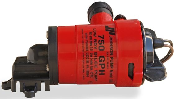
Index - Indice

Svenska.....................................................................................................................................................................3
English .....................................................................................................................................................................6
Deutsch.....................................................................................................................................................................9
Français ................................................................................................................................................................ 12
Español ................................................................................................................................................................. 15
Italiano.................................................................................................................................................................... 18

Besök www.johnson-pump.com för mer information om vår världsomspännande organisation, våra godkännanden,
certifieringar och lokala representanter. SPX Corporation förbehåller sig rätten att ändra design och material utan
föregående avisering. Designelement, konstruktionsmaterial och dimensioner som beskrivs i denna bulletin gäller
endast som information och skall alltid bekräftas skriftligt för att vara gällande.
For more information about our worldwide locations, approvals, certifications, and local representatives, please visit
www.johnson-pump.com. SPX Corporation reserves the right to incorporate our latest design and material changes
without notice or obligation. Design features, materials of construction and dimensional data, as described in this
bulletin, are provided for your information only and should not be relied upon unless confirmed in writing.
Für weitere Informationen über unsere weltweiten Standorte, Zulassungen, Zertifizierungen und unsere Vertreter vor
Ort, besuchen Sie bitte unsere Webseite: www.johnson-pump.com. Die SPX Corporation behält sich das Recht vor,
die neuesten Konstruktions- und Werkstoffänderungen ohne vorherige Ankündigung und ohne Verpflichtung hierzu
einfließen zu lassen. Konstruktive Ausgestaltungen, Werkstoffe sowie Maßangaben, wie sie in dieser Mitteilung
beschrieben sind, sind nur zur Information. Alle Angaben sind unverbindlich, es sei denn, sie wurden schriftlich
bestätigt.
Pour plus d’information sur nos succursales internationales, nos approbations, nos certifications et nos représentants
locaux, veuillez consulter notre site Internet au www.johnson-pump.com. SPX Corporation se réserve le droit
d’incorporer nos plus récents concepts ainsi que tout autre modification importante sans préavis ou obligation. Les
éléments décoratifs, matériaux de construction et les données dimensionnelles, tels qu’énoncés dans ce communiqué,
sont fournis pour votre information seulement et ne doivent pas être considérés comme officiels à moins d’avis
contraire par écrit.
Para más información sobre nuestras oficinas a nivel mundial, aprobaciones, certificaciones y representantes locales,
por favor visite www.johnson-pump.com. SPX Corporation se reserva el derecho de incorporar nuestro diseño más
reciente y cambios materiales sin necesidad de notificación previa u obligación de ningún tipo. Características de
diseño, materiales de construcción y dimensiones, tal y como están descritas en este boletín, son proporcionadas sólo
con fines informativos y no deben ser usados como referencia a menos que sean confirmados por escrito.
Per ottenere maggiori informazioni sulle nostre sedi nel mondo, autorizzazioni, certificazioni, e rappresentanti locali,
potete visitare il sito www.johnson-pump.com. La SPX Corporation si riserva il diritto di apportare cambiamenti ai
propri design e materiali senza preavviso o vincolo. Le caratteristiche del design, i materiali di costruzione e i dati
dimensionali, così come descritti nel presente bollettino, sono forniti solo per vostra informazione e non saranno
oggetto di obbligazione salvo autorizzazione confermata per iscritto.

                                                                           Made in USA

                                                                            Garanti 3 år
                                                                          Warranty 3 years
                                                                          Garantie 3 Jahren
                                                                           Garantie 3 ans
                                                                          Garantía 3 años
                                                                           Garanzia 3 anni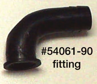
> Svenska

    Low Boy Länspump                         Elektrisk installation
    Lågprofilpump designad för att           1. Anslut den bruna kabeln till
    underlätta montering i trånga                batteriets pluspool (+).
    utrymmen. Perfekt för båtar där          2.   Anslut den svarta kabeln till
    länspumpen är monterad under                  batteriets minuspol (-).
    inombords- eller I/O motorn. L550        3.   Ta inte bort mer än
    LB är utrustad med Duraport-                  nödvändigt av plasten runt
    anslutningar för att underlätta in-           kabeln. Alla elanslutningar
    stallationen samt undvika sprickor            måste alltid sitta över
    vid åtdragning. Pumpen levereras              högsta vattennivån.
    med både rak och 90° anslutning.              Kabelskarvarna ska tätas
    Max längd 146 mm – 5.75"                      med ett marint tätningsmedel
    Bredd 81 mm – 3.2"                            för att förhindra oxidation.
    Höjd 72 mm – 2.82"                            Garantin är inte giltig om
    Kabelarea 1.3 mm2 – 16 GA                     kabelskarvarna placeras så
                                                  att de riskerar att hamna
    Installation Instructions                     under vatten.
    1. Placera pumpen vid lägsta
                                             4.   Använd en 5A säkring vid
         punkten. Pumpen kan place-
                                                  elinstallationen.
         ras horisontellt eller vertikalt.
                                             5.   Pumpen får inte köras torr i
    2.       Välj en plats där vattnet ska
                                                  mer än 10 sekunder.
             pumpas överbord - så högt
             som möjligt över vattenlinjen   6.   Om en nivåströmbrytare
             och så nära pumpen som               används i kombination med
             möjligt. Montera en 19 mm            pumpen, måste nivåström-
             (3/4") bordgenomföring i ett         brytaren placeras högre än
             27 mm hål.                           pumpens impeller för att sä-
                                                  kerställa att pumpen stängs
                                                  av som den ska.

Översättning av originalinstruktionerna                                           3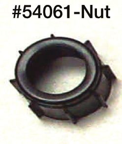
> Svenska
Montering/demontering av                 att den passar in i skårorna
motor-/impellerenheten                   på pumphuset. Pressa ned
1. Lyft låshaken och vrid de två         och vrid vingarna medurs.
    vingarna moturs och lyft ur          Prova om enheten är rätt
    enheten.                             placerad genom att vrida
2.   Innan enheten återplaceras,         vingarna moturs utan att lyfta
     kontrollera att tätningen sitter    låshaken. Enheten ska då
     på plats. Smörj tätningen           sitta fast ordentligt.
     med mineral- eller vegetabi-
     lisk olja. Placera enheten så

                                        Lyft låshaken
                                        Lift tab
                                        Die Zunge heben
                                        Soulever la languette
                                        Levantar la lengüeta
                                        Levare la linguetta

             Demontera                              Montera
             Remove                                 Reinstall
             Entfernen                              Montieren
             Enlever                                Remonter
             Quitar                                 Montrar
             Rimuovere                              Rimontare

                  Tätning
                  Seal
                  Dichtung
                  Joint
                  Junta
                  Guarnizione

4                                                   Översättning av originalinstruktionerna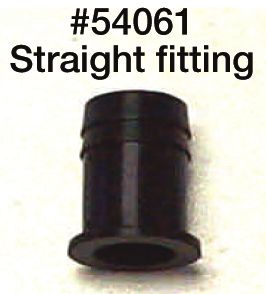
> Svenska
    Installationsanvisningar för
    gängat utlopp:
    Omonterade anslutningar
    1. Installera lämplig anslutning,
       rak eller 90° i ¾" anslutnings-
       muttern. Placera därefter
       tätningsbrickan i anslutnings-
       muttern.
    2.       Installera slangklämman löst
             på utloppsslangen och mon-
             tera slangen på anslutningen.
             Fäst slangklämman.
    3.       Gänga den monterade anslut-
             ningen på pumpens utlopp,
             placera slangen och dra åt
             anslutningsmuttern. Drag åt
             för hand och ytterligare ett ¼
             varv för att låsa anslutningen.

    Förmonterade anslutningar
    1. Installera slangklämman löst
        på utloppsslangen. Installera
        slangen på anslutningen med
        hullingar och placera som
        erforderligt.
    2.       Fäst slangklämman och
             kontrollera därefter att an-
             slutningsmuttern är tillräckligt
             åtdragen.
    De gängade muttrarna ska
    inte dras åt mekaniskt. Dras
    de åt för hårt finns risk för
    skador.
    Marina tätningsmedel behövs inte.
    Regelbunden kontroll av produk-
    tens täthet rekommenderas.

Översättning av originalinstruktionerna                 5
> English
Low Boy Bilge Pump Wiring the pump
Low Profile pump designed for 1. Connect the brown wire from
ease of mounting and removal in the pump to the positive (+)
tight bilge areas. Perfect for ves- fused side of the battery.
sels with bilge pumps mounted 2. Connect the black wire
beneath inboard or I/O engines. coming off of the pump to
Removable cartridge style. Easy- the negative (-) side of the
to-install Dura-Port discharge battery.
ports to eliminate stress cracking 3. Do not cut any wire insulation
caused by over-tightened hose more than 3” and keep all
clamps. The pumps include both a connection above the water
straight and a 90° smooth elbow levels, keep all connections
Dura-Port as well as a removable high and dry. A marine grade
check valve. sealant/liquid electrical tape
Max length 146 mm – 5.75" is recommended to seal
Width 81 mm – 3.2" loose wire ends. A submer-
Height 72 mm – 2.82" ged splice will render the
Wire size 1.3 mm2 – 16 GA warranty void.
4. Fuse all cartridge style
Installation Instructions
pumps at 5A.
1. Mount pump at lowest point
in the bilge. 5. Do not run pump dry for more
than 10 seconds.
2. Select a point where
bilge water is to be pumped 6. If you are using a float switch
overboard, at least 1 foot in conjunction with this pump,
above the waterline and the be sure that the float switch
shortest distance from the is higher than the impeller
pump. Install a ¾" thru hull. A level of the pump to assure
1-1/16 hole will be required. proper shutoff of the pump.
The pump can be mounted
horizontally or vertically, ho-
wever the pump does need to
be installed in the lowest part
of the bilge.
6 Original instructions> English
To remove or replace power cams on wither side of the
cartridge power cartridge with the two
1. Life tab and rotate the two slots in the outer housing.
fins in a counter clockwise Press down and twist in a
direction and lift out. clockwise rotation. To ensure
2. To reinstall, first make sure that the power cartridge is
the O-ring is properly loca- properly located, twist fins in
ted. Coat the O-ring with a a counter clockwise direction
light film of vegetable oil or without lifting tab. Cartridge
mineral oil, then align the two should stay in place.
Lyft låshaken
Lift tab
Die Zunge heben
Soulever la languette
Levantar la lengüeta
Levare la linguetta
Demontera Montera
Remove Reinstall
Entfernen Montieren
Enlever Remonter
Quitar Montrar
Rimuovere Rimontare
Tätning
Seal
Dichtung
Joint
Junta
Guarnizione
Original instructions 7> English
Threaded Discharge Installa-
tion Instructions:
Unassembled Fittings
1. Install the appropriate barb
fitting straight or 90° into the
¾" connector nut. Place the
sealing washer into the con-
nector nut afterwards.
2. Install the hose clamp loosely
on the discharge hose and
install the hose onto the
barb. Tighten the hose clamp
securely.
3. Thread the assembled con-
nector nut onto the pump
discharge port, position the
hose and tighten the connec-
tor nut. Tighten the assembly
¼ turn past hand tightness.
Pre-assembled fittings
1. Install the hose clamp loosely
on the discharge hose. Install
the hose onto the barb fitting
and position as neces-
sary. Tighten the hose clamp
securely.
2. Check the tightness of the
connector nut.
Threaded nuts do not require
mechanical tightening. Do
not over tighten, damage may
occur.
Marine type sealants are not requi-
red, periodic check for tightness is
recommended.
8 Original instructions> Deutsch
Flache Bilgenpumpe Leitungsführung der Pumpe
Diese flachliegende Pumpe erleich- 1. Schließen Sie die braune
tert den Einbau und das Entfernen Leitung von der Pumpe an
in engen Bilgenbedingungen. die positive (+) abgesicherte
Ideal für Schiffe mit Bilgenpumpen Seite des Akku.
unter Innenbord- oder I/O-Motoren. 2. Schließen Sie die schwarze
Entfernbare Einbauausführung. Leitung von der Pumpe an
Einfach zu installierende Dura-Port- die negative (-) Seite des
Auslaufstutzen zur Beseitigung der Akku.
Gefahr von Spannungrissbildung, 3. Schneiden Sie die Isolation
die als Ergebnis der zu stark angezo- nicht mehr als 3" ab und
genen Schlauchklemmen entstehen halten Sie die Verbindung
kann. Die Pumpen enthalten sowohl über dem Wasserpegel und
einen geraden als auch einen 90° alle Verbindungen hoch und
glatten Krümmer-Dura-Port sowie trocken. Zur Abdichtung von
eine entfernbare Rückschlagklappe.. freien Leitungsenden wird
Max. Länge 146 mm – 5.75" Isolierband für See-/Was-
Breite 81 mm – 3.2" seranwendungen empfoh-
Höhe 72 mm – 2.82" len. Beim Eintauchen der
Leitungsgröße 1.3 mm2 – 16 GA Kabelverbindung ins Wasser
verliert die Garantie ihre
Einbauanweisungen Gültigkeit.
1. Bauen Sie die Pumpe in den
4. Sichern Sie alle einzubau-
niedrigsten Punkt der Bilge ein.
ende Pumpen mit 5 A ab.
2. Zum Pumpen des Bilgenwas-
5. Die Pumpe nicht länger als
sers über Bord wählen Sie
10 Sekunden trocken laufen
einen Punkt, der mindestens
lassen.
1 Fuß über dem Wasserpegel
liegt und möglichst nah der 6. Falls Sie einen Schwimmer-
Pumpe ist. Bauen Sie eine schalter mit dieser Pumpe
¾” Schiffskörperdurchfüh- verwenden, stellen Sie sicher,
rung. Dazu wird eine 1-1/16 dass der Schwimmerschalter
Bohrung benötigt. Die Pumpe höher liegt als das Flügelrad
kann horizontal eingebaut der Pumpe, damit die Pumpe
werden, doch muss sie nicht in richtig ausschalten kann.
den niedrigsten Teil der Bilge
eingebaut werden.
Übersetzung der Original-Betriebanleitungen 9> Deutsch
Entfernen oder Ersetzen des die zwei Nocken auf der
Antriebs breiteren Seite des Antriebs
1. Heben Sie die Lasche an und mit Hilfe der zwei Einschnitte
rotieren Sie die zwei Flügel im äußeren Gehäuse aus.
gegen den Uhrzeigersinn und Drücken und drehen Sie sie
nehmen Sie sie aus. im Uhrzeigersinn. Um sicher
2. Zum Einbauen stellen Sie zu stellen, dass der Antrieb
zuerst sicher, dass der richtig liegt, drehen Sie die
O-Ring richtig liegt. Tragen Flügel gegen den Uhrzei-
Sie auf den O-Ring eine gersinn, ohne die Lasche
dünne Schicht pflanzliches anzuheben. Der Einsatz sollte
oder Mineralöl, richten Sie auf seiner Stelle bleiben.
Lyft låshaken
Lift tab
Die Zunge heben
Soulever la languette
Levantar la lengüeta
Levare la linguetta
Demontera Montera
Remove Reinstall
Entfernen Montieren
Enlever Remonter
Quitar Montrar
Rimuovere Rimontare
Tätning
Seal
Dichtung
Joint
Junta
Guarnizione
10 Übersetzung der Original-Betriebanleitungen> Deutsch
Gewindeauslauf einbauen:
Nicht vormontiertes Zubehör
1. Installieren Sie die richtige
Schlauchtülle gerade oder unter
einem Winkel von 90° in die ¾" An-
schlussmutter. Legen Sie die Dich-
tung danach in die Anschlussmutter.
2. Bauen Sie die Schlauchklemme auf
die Auslaufleitung und die Leitung
an die Schlauchtülle. Ziehen Sie die
Schlauchklemme sicher an.
3. Drehen Sie die vormontierte Verbin-
dungsmutter an den Auslaufstutzen
der Pumpe und bringen Sie die
Verbindungsmutter in Stellung.
Ziehen Sie die Baugruppe nach dem
Anziehen mit der Hand noch um ¼
Drehung an.
Vormontiertes Zubehör
1. Installieren Sie die Schlauchklemme
lose an die Auslaufleitung. Instal-
lieren Sie den Schlauch an die
Schlauchtülle und bringen Sie ihn
bei Bedarf in die richtige Stellung.
Ziehen Sie die Schlauchklemme
sicher an.
2. Überprüfen Sie die Spannung der
Verbindungsmutter.
Gewindemuttern brauchen keine
mechanische Anziehung. Nicht zu
stark anziehen, ansonsten besteht
die Gefahr von Beschädigungen.
Dichtmittel für Seeanwendungen sind
nicht nötig, überprüfen Sie regelmäßig
die Dichtheit.
Übersetzung der Original-Betriebanleitungen 11> Français
Pompes de cale Low Boy Câbler la pompe
Pompes surbaissées conçues pour 1. Raccordez le fil brun de la
montage et démontage facile dans pompe à la borne positive (+)
des parties de cale exigües. Parfaites protégée par un fusible de la
pour des bateaux avec des pompes batterie.
de cale montées sous les moteurs à 2. Raccordez le fil noir de la
bord ou I/O. De type cartouche amo- pompe à la borne négative (-)
vible. Facile à installer. Orifice de re- de la batterie.
foulement Dura-Port pour éliminer les
3. Ne dénudez aucun fil de plus
fissures de contraintes causées par
de 3”et maintenez tous les
des brides trop serrées. Les pompes
raccordements au-dessus
comprennent un Dura-Port droit ainsi
des niveaux d’eau, maintenez
qu’un autre en angle doux de 90° de
tous les raccordements en
même qu’un clapet de non-retour.
position élevée et sèches.
Longueur max 146 mm – 5.75" Une bande isolante/liquide
Largeur 81 mm – 3.2" pour usage électrique de
Hauteur 72 mm – 2.82" type marine est recomman-
Calibre de fil 1.3 mm2 – 16 GA dée pour isoler les termi-
naisons des fils libres. Une
Instructions d’Installation épissure noyée annulera la
1. Montez la pompe au point le garantie.
plus bas de la cale.
4. Protégez par fusible de 5A
2. Choisissez un point d’où l’eau toutes les pompes de type
de cale doit être pompée vers cartouche.
l’extérieur, à au moins 1 pied au-
5. Ne pas faire fonctionner la
dessus de la ligne de flottaison
pompe à sec durant plus de
et à la distance la plus courte de
10 secondes.
la pompe. Installez un passe-
coque de ¾”. Un trou de 1-1/16 6. Si vous utilisez un interrup-
sera nécessaire. La pompe peut teur à flotteur relié à cette
être montée horizontalement pompe, assurez-vous que
ou verticalement, toutefois la l’interrupteur à flotteur est
pompe n’est pas obligée à être placé plus haut que le niveau
installées dans la partie infé- de la turbine de la pompe
rieure de la cale. pour garantir un déclenche-
ment correct de la pompe.
12 Traduction du manuel d'instruction d'origine> Français
Pour enlever ou remplacer la rale, ensuite alignez les deux
cartouche d’entraînement cames sur les deux côtés de
1. Levez l’onglet et faites tour- la cartouche avec les deux
ner les deux ailettes dans le fentes dans le carter extérieur
sens contraire des aiguilles Appuyez vers le bas et tour-
d’une montre et sortez la nez dans le sens des aiguilles
cartouche. d’une montre. Pour vous
2. Pour la réinstaller, assurez- assurez que la cartouches
vous premièrement que le est bien placée, tournez les
joint torique est correcte- ailettes en sens contraire des
ment placé. Enduisez le joint aiguilles d’une montre sans
torique d’une légère couche lever l’onglet. La cartouche
d’huile végétale ou miné- doit rester en place.
Lyft låshaken
Lift tab
Die Zunge heben
Soulever la languette
Levantar la lengüeta
Levare la linguetta
Demontera Montera
Remove Reinstall
Entfernen Montieren
Enlever Remonter
Quitar Montrar
Rimuovere Rimontare
Tätning
Seal
Dichtung
Joint
Junta
Guarnizione
Traduction du manuel d'instruction d'origine 13> Français
Instructions d’Installation du Refou-
lement Fileté:
Accessoires démontés
1. Installez la pièce de scellement app-
ropriée, droite ou à 90° dans l’écrou
de raccordement de ¾". Placez
ensuite la rondelle d’étanchéité dans
l’écrou de raccordement.
2. Installez sans serrage la bride du
tuyau et installez le tuyau sur la pièce
de scellement. Serrez la bride du
tuyau de manière sûre.
3. Vissez l’écrou de raccordement as-
semblé sur l’orifice de refoulement de
la pompe, positionnez le tuyau et ser-
rez l’écrou de raccordement. Serrez
l’assemblage de ¼ de tour à la main.
Accessoires pré assemblés
1. Installez sans serrage la bride du
tuyau et installez le tuyau sur la pièce
de scellement. Installez le tuyau sur
la pièce de scellement et position-
nez-le comme nécessaire Serrez la
bride du tuyau de manière sûre.
2. Contrôlez le serrage de l’écrou de
raccordement.
Les écrous filetés ne nécessitent
pas de serrage mécanique. Ne
serrez pas trop, des dommages
peuvent apparaître.
Les étanchéités de type marine ne sont
pas nécessaires, des contrôles périodi-
ques du serrage sont par contre recom-
mandés.
14 Traduction du manuel d'instruction d'origine> Español
Bomba de sentina Low Boy Cableado eléctrico de la
Bomba de bajo perfil diseñada para un bomba
montaje y desmontaje fácil en zonas 1. Conecte el cable marrón de
de sentina estrechas. Perfecta para la bomba al polo positive (+)
embarcaciones con bombas de sentina de la batería.
montadas bajo motores a bordo o 2. Conecte el cable negro que
I/O. Estilo de cartucho extraíble. sale de la bomba al polo
Puertos de descarga Dura-Port fáciles negativo (-) de la batería.
de instalar para eliminar las grietas
3. No corte el aislamiento de los
provocadas por abrazaderas para
cables más de 3” y mantenga
mangueras demasiado apretadas. Las
todas las conexiones por
bombas incluyen tanto un codo fino
encima del nivel del agua.
recto y de 90º Dura-Port como una
Mantenga las conexiones en
válvula reguladora extraíble.
alto y secas. Se recomienda
Longitud máxima 146 mm – 5.75" utilizar cinta eléctrica con sel-
Grosor 81 mm – 3.2" lante/líquido de grado marino
Altura 72 mm – 2.82" para sellar las terminaciones
Tamaño del cable 1.3 mm2 – 16 GA sueltas de los cables. Un
empalme sumergido hará que
Instrucciones de instalación la garantía se anule.
1. Monte la bomba en el punto más
4. Instale fusibles en todas las
bajo de la sentina.
bombas de tipo cartucho a
2. Seleccione un punto en el que 5A.
el agua de la sentina se va a
5. No deje que la bomba fun-
bombear por la borda, al menos
cione en seco durante más
1 pie por encima de la línea de
de 10 segundos.
flotación y a la distancia más
corta desde la bomba. Instale un 6. Si está utilizando un inter-
accesorio de ¾” atravesando el ruptor de flotador junto con
casco. Se necesitará un agujero esta bomba, asegúrese de
de 1-1/16. La bomba puede que el interruptor de flotador
montarse de forma horizontal o está más alto que el nivel
vertical, sin embargo ésta nece- del impulsor de la bomba
sita ser instalada en la parte más para asegurar un correcto
baja de la sentina. apagado de la bomba.
Traducción de instrucciones originales 15> Español
Para quitar o sustituir el cartu- lado más pálido del cartucho
cho eléctrico de electricidad con las dos
1. Levante la lengüeta, gire las ranuras en la carcasa exterior.
dos aletas en sentido cont- Presione hacia abajo y gire
rario a las agujas del reloj y en el sentido de las agujas
quítelo. del reloj. Para asegurarse de
2. Para volver a instalarlo, que el cartucho de electrici-
primero asegúrese de que la dad está bien colocado, gire
anilla en O está bien colo- las dos aletas en el sentido
cada. Cubra la anilla en O contrario a las agujas del reloj
con una fina capa de aceite sin levantar la lengüeta. El
vegetal o mineral, después cartucho debería permanecer
alinee las dos levas en el en su sitio.
Lyft låshaken
Lift tab
Die Zunge heben
Soulever la languette
Levantar la lengüeta
Levare la linguetta
Demontera Montera
Remove Reinstall
Entfernen Montieren
Enlever Remonter
Quitar Montrar
Rimuovere Rimontare
Tätning
Seal
Dichtung
Joint
Junta
Guarnizione
16 Traducción de instrucciones originales> Español
Instrucciones de instalación para la
descarga con rosca:
Dispositivos no ensamblados
1. Instale el dispositivo de lengüetas
en flecha adecuado recto o en
90º en la tuerca conectora de ¾".
Coloque la arandela de sellado en la
tuerca conectora después de ello.
2. Instale la abrazadera para tubos
holgadamente en la tubería de
descarga e instale la tubería en el
dispositivo de lengüetas en flecha.
Apriete la abrazadera de la tubería.
3. Enrosque la tuerca conectora
montada en el puerto de descarga
de la bomba, coloque la tubería y
apriete la tuerca conectora. Apriete
el ensamblaje ¼ de vuelta más del
ajuste con la mano.
Dispositivos pre-ensamblados
1. Instale la abrazadera de la tubería
holgadamente en la tubería de
descarga. Instale la tubería en el
dispositivo de lengüetas en flecha
y colóquelo como sea necesario.
Apriete la abrazadera de la tubería.
2. Compruebe el ajuste de la tuerca
conectora.
Las tuercas de rosca no necesitan
un ajuste mecánico. No apriete de-
masiado, podría provocar daños.
No se necesitan sellantes de tipo
marino, se recomienda una revisión
periódica para comprobar los ajustes.
Traducción de instrucciones originales 17> Italiano
Pompa di Sentina Low Collegamento della pompa.
Boy 1. Collegare il cavo marrone
Pompa a basso profilo proget- della pompa all'estremità
tata per una facilità di montaggio e positiva dotata di fusibile (+)
smontaggio in aree di sentina ridotte. della batteria.
Perfetta per imbarcazioni con pompe 2. Collegare il cavo nero della
di sentina montate sotto l’entrobordo pompa all'estremità negativa
o motori I/O. Modello con cartuccia (-) della batteria.
rimovibile. Porte di scarico Dura-Port 3. Non tagliare nessun cavo
semplici da installare per eliminare più di 3” e mantenere tutti i
rotture causate da fascette serra tubo collegamenti sopra il livello
troppo strette. La pompa comprende dell’acqua, tenere i cavi in
sia un raccordo Dura-Port a gomito alto e asciutti. Si raccomanda
dritto sia uno a 90° e una valvola di di utilizzare un nastro elett-
controllo rimovibile. rico liquido/sigillante di tipo
Lunghezza nautico per unire le estremità
massima 146 mm – 5.75" libere dei cavi. Qualsiasi col-
Profondità 81 mm – 3.2" legamento sotto il livello
Altezza 72 mm – 2.82" dell’acqua renderà nulla la
Dimensione garanzia.
del cavo 1.3 mm2 – 16 GA 4. Dotare tutte le pompe mo-
dello cartuccia di un fusibile
Istruzioni d’installazione da 5A.
1. Montare la pompa nel punto più
basso della sentina. 5. Non avviare la pompa a
secco per più di 10 secondi.
2. Scegliere un punto in cui l'acqua
di sentina dovrà essere pompata 6. In caso di utilizzo di un
fuoribordo, almeno 1 piede al interruttore galleggiante con
di sopra della linea dell’acqua questa pompa, assicu-
e alla minore distanza pos- rarsi che esso sia più alto
sibile dalla pompa. Installare del livello della ventola della
attraverso uno scafo da ¾”. Sarà pompa in modo da assicurare
necessario un foro da 1-1/16. il corretto spegnimento della
La pompa può essere montata stessa.
orizzontalmente o verticalmente,
e comunque nella parte inferiore
della sentina.
18 Traduzione delle istruzioni originali> Italiano
Togliere o sostituire le cartucce dalla cartuccia di alimenta-
di alimentazione zione con le due scanalature
1. Alzare la linguetta, ruotare le nell'alloggiamento esterno.
due alette in senso antiorario e Premere verso il basso e
far scorrere fuori la cartuccia. ruotare in senso orario. Per
2. Per reinstallarla, assicurarsi assicurarsi che la cartuccia di
prima di tutto che l’anello a O alimentazione sia adeguata-
sia adeguatamente posizio- mente posizionata, ruotare
nato. Rivestire l’anello a O con le alette in senso antiorario
un sottile strato di olio vege- senza sollevare la linguetta.
tale o minerale, poi allineare le La cartuccia dovrebbe rima-
due camme su entrambe i lati nere al proprio posto.
Lyft låshaken
Lift tab
Die Zunge heben
Soulever la languette
Levantar la lengüeta
Levare la linguetta
Demontera Montera
Remove Reinstall
Entfernen Montieren
Enlever Remonter
Quitar Montrar
Rimuovere Rimontare
Tätning
Seal
Dichtung
Joint
Junta
Guarnizione
Traduzione delle istruzioni originali 19> Italiano
Istruzioni per l’installazione dello
scarico filettato:
Accessori smontati
1. Installare l’accessorio a punta
diritto o a 90° nel dado del con-
nettore da ¾". Subito dopo,
posizionare la rondella sigillante
nel dado del connettore.
2. Installare la fascetta serra-tubo
lenta sul tubo di scarico e instal-
lare il tubo sulla punta. Stringere
la fascetta serra-tubo.
3. Far passare il dado del con-
nettore nella porta di scarico
della pompa, posizionare il tubo e
stringere il dado del connettore.
Stringere l’assemblaggio string-
endo a mano ed effettuando una
rotazione di ¼ di giro.
Accessori pre-assemblati
1. Stringere la fascetta serra-tubo
sul tubo di scarico. Installare
il tubo sull’accessorio a punta
e posizionarlo correttamente.
Stringere la fascetta serra-tubo.
2. Controllare di aver stretto il
dado del connettore.
I dadi filettati non devono essere
avvitati meccanicamente. Non
avvitare troppo per non causare
danni.
Non è necessario utilizzare sigillanti
di tipo nautico, si consiglia di control-
lare periodicamente l’avvitatura.
20 Traduzione delle istruzioni originaliAvfallshantering/materialåtervinning Vid avfallshantering ska produkten lämnas för destruktion/återvinning enligt gällande lagstiftning. Vid tillämpliga fall demonteras och sorteras produkten i ingående materialfraktioner. Waste handling/material recycling At the products end of life, please dispose of the product according to applicable law. Where applicable, please disassemble the product and recycle the parts material. Entsorgung/Recycling Nach Lebensdauerende entsorgen Sie die Pumpe nach den örtlichen Vorschriften. Nach Möglichkeit demontieren Sie Teile der Pumpe um sie dem Recycling-Process zuzuführen. Gestion des déchets/recyclage des matériaux Lorsque le matériel arrivera en fin de vie, veuillez le mettre au rebut en fonction des lois applicables. Lorsque c'est possible, veuillez démonter le matériel et recycler les pièces pouvant l'être Desguace/Reciclado Al final de la vida del equipo disponga de este de acuerdo a la ley. Donde sea de aplicación desmonte el equipo y recicle los diferentes materiales. Gestione dei rifiuti/riciclaggio dei materiali Al termine della vita del prodotto si prega di smaltire il prodotto secondo le leggi in vigore per queste operazioni. Quando possibile, si raccomanda di smontare il prodotto e riciclare i materiali dei componenti.
Warranty Information                              IN NO EVENT WILL JOHNSON PUMPS OF
                                                  AMERICA BE LIABLE FOR MORE THAN
Johnson Pumps of America of 1625 Hunter           THE SALES PRICE OF THE PRODUCT.
Road, Suite B Hanover Park, Illinois 60133        UNDER NO CIRCUMSTANCES WILL
warrants to the original consumer purchaser       JOHNSON BE LIABLE FOR ANY LOST
that this product will be free from defects in    PROFITS, INCIDENTAL OR CONSEQUEN-
material and work¬manship, providing that the     TIAL COSTS, EXPENSES, OR DAMA-
case is not opened or the pump other¬wise         GES. THE LIMITATION ON LIA¬BILITY
abused for a period of three (3) year from the    FOR LOST PROFITS, INCIDENTAL OR
date originally purchased.                        CONSEQUEN¬TIAL COST EXPENSES OR
                                                  DAMAGES SHALL SURVIVE ANY FAI-
The exclusive remedy of the consumer purcha-      LURE OF ESSENTIAL PURPOSE OF THIS
ser in the event the product does not meet this   LIMITED WAR¬RANTY. Some states do not
express Limited Warranty is to return the pump    allow the exclusive or limitation of incidental
to Johnson Pump at the above address, freight     or consequential damages, so the above
prepaid with your sales receipt. IMPORTANT:       limitation may not apply to you.
FOR THIS WARRANTY TO BE EFFECTIVE,
JOHNSON PUMP MUST BE SUPPLIED                     NO EXPRESS OR LIMITED WARRANTY, IN-
WITH THE ORIGI¬NAL PURCHASE DATE                  CLUDING WARRAN¬TY OF MERCHANTA-
OF THE PRODUCT. THE ACCEPTANCE                    BILITY AND FITNESS SHALL EXTEND FOR
BY JOHNSON PUMP OF ANY PRODUCT                    ANY PERIOD OF TIME GREATER THAN
RETURNED SHALL NOT BE DEEMED AN                   ONE YEAR FROM THE DATE OF ORIGINAL
ADMISSION THAT SUCH PRODUCT IS                    PURCHASE OF THIS PRODUCT. Some
DEFECTIVE OR IN VIOLATION OF ANY                  states do not allow limitation on how long an
WARRANTY. THE COMPANY RESERVES                    implied warran¬ty lasts so the above limitation
THE RIGHT TO REPAIR OR REPLACE THE                may not apply to you. CAUTION - War-
PRODUCT.                                          ranty void if seal on product is broken, if any
                                                  electric cord is cut, if electric splices become
NO REPRESENTATIVE OR OTHER PER-                   sub¬merged, or if product is installed contrary
SON IS AUTHORIZED TO ASSUME FOR                   to instructions or warnings.
JOHNSON PUMP ANY ADDITIONAL LIA-
BILITY IN CONNECTION WITH THE SALE
OF ITS PRODUCTS OR TO ALTER THIS
WARRANTY IN ANY WAY.

22
Johnson Pumps of America Inc. 1625 Hunter Road, Suite B, Hanover Park, Illinois, 60133, USA Tel. +1 847 671 7867. Fax +1 847 671 7909. E-mail:johnson-pump.usa@processequipment.spx.com SPX Johnson Pump Marine AB Nastagatan 19, P.O. Box 1436 SE-701 14 Örebro, Sweden Phone: +46 (0)19 21 83 00 Fax: +46 (0)19 27 23 72 E-mail: johnson-pump.marine@processequipment.spx.com For more information about our worldwide locations, approvals, certifications, and local representatives, please visit www.johnson-pump.com. SPX Corporation reserves the right to incorporate our latest design and material changes without notice or obligation. Design features, materials of construction and dimensional data, as described in this bulletin, are provided for your information only and should not be relied upon unless confirmed in writing. Copyright © 2009 SPX Corporation P/N 52220 Rev. 8/09-0
Vous pouvez aussi lire