Hughes 9502 User Guide - Hughes Network Systems
←
→
Transcription du contenu de la page
Si votre navigateur ne rend pas la page correctement, lisez s'il vous plaît le contenu de la page ci-dessous
Hughes 9502
User Guide

H64151
Revision B
May 1, 2020

11717 Exploration Lane, Germantown, MD 20876

Phone (301) 428-5500 Fax (301) 428-1868/2830
Copyright © 2013, 2017, 2019, 2020 Hughes Network Systems, LLC
All rights reserved. This publication and its contents are proprietary to Hughes Network Systems,
LLC. No part of this publication may be reproduced in any form or by any means without the
written permission of Hughes Network Systems, LLC, 11717 Exploration Lane, Germantown,
Maryland 20876.
Hughes Network Systems, LLC has made every effort to ensure the correctness and completeness
of the material in this document. Hughes Network Systems, LLC shall not be liable for errors
contained herein. The information in this document is subject to change without notice. Hughes
Network Systems, LLC makes no warranty of any kind with regard to this material, including, but
not limited to, the implied warranties of merchantability and fitness for a particular purpose.

                                        Trademarks
HUGHES and Hughes Network Systems are trademarks of Hughes Network Systems, LLC. All other
trademarks are the property of their respective owners.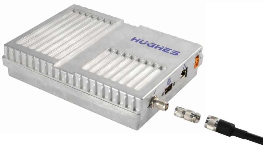
Contents
Understanding safety alert messages .................................................... 5
Messages concerning personal injury / Messages concernant des blessures
corporelles ......................................................................................................... 5
Messages concerning property damage / Messages concernant des dommages
matériels............................................................................................................ 6
Safety symbols ................................................................................................... 6
Chapter 1
Product description .............................................................................. 13
Contents of the Hughes 9502 kit ...................................................................... 13
Optional mounting accessories ........................................................................ 14
Main features of the 9502 ................................................................................ 14
Interfaces......................................................................................................... 15
Terminal specifications .................................................................................... 17
Information for maintenance ........................................................................... 18
   For users: .................................................................................................... 18
   For distribution providers: .......................................................................... 18
Date of manufacture ........................................................................................ 18
Manufacturer contact ...................................................................................... 18
Chapter 2
Configuration via Web UI ..................................................................... 19
Web UI layout .................................................................................................. 19
  Home tab .................................................................................................... 19
  Status bar ................................................................................................... 21
  Connections tab .......................................................................................... 24
  Settings tab ................................................................................................. 28
  M2M page .................................................................................................. 34
  Security Passwords ..................................................................................... 36
  Enhanced Security Settings page ................................................................. 37
  SMS pages .................................................................................................. 39
Chapter 3
Operational features............................................................................. 41
LEDs ................................................................................................................. 41
Function button ............................................................................................... 41
Network mode ................................................................................................. 41
   NAT mode ................................................................................................... 41
   NAPT mode ................................................................................................. 42
   Relay mode ................................................................................................. 42
   PPPoE mode ............................................................................................... 42
Remote control ................................................................................................ 43
Remote upgrade and file transfer .................................................................... 44
Security............................................................................................................ 44

                                                                                                 Contents
                                                                                         H64151 Revision B                  3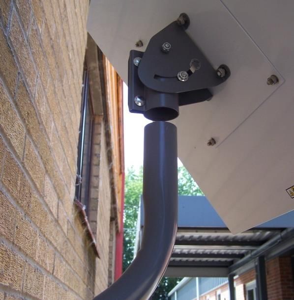
Wake on LAN (any packet) ............................................................................... 44
Serial pin power control ................................................................................... 45
ATC .................................................................................................................. 45
Watchdog ........................................................................................................ 45
GNSS................................................................................................................ 45
Chapter 4
Installation instructions ....................................................................... 47
Inspecting the parts ......................................................................................... 47
Optional installation items ............................................................................... 47
Determining where to install the ODU ............................................................. 47
ODU installation using the basic fix mount kit (P/N 3004066-0002) .................. 49
Mounting the azimuth elevation bracket ......................................................... 50
Mounting the azimuth elevation bracket onto the pole .................................... 51
Attaching RF cable to ODU ............................................................................... 52
Attaching RF cable to the Hughes 9502 IDU ..................................................... 53
Installing the SIM Card ..................................................................................... 53
Connecting power leads to the Hughes 9502 IDU ............................................. 54
Powering up the Hughes 9502 ......................................................................... 55
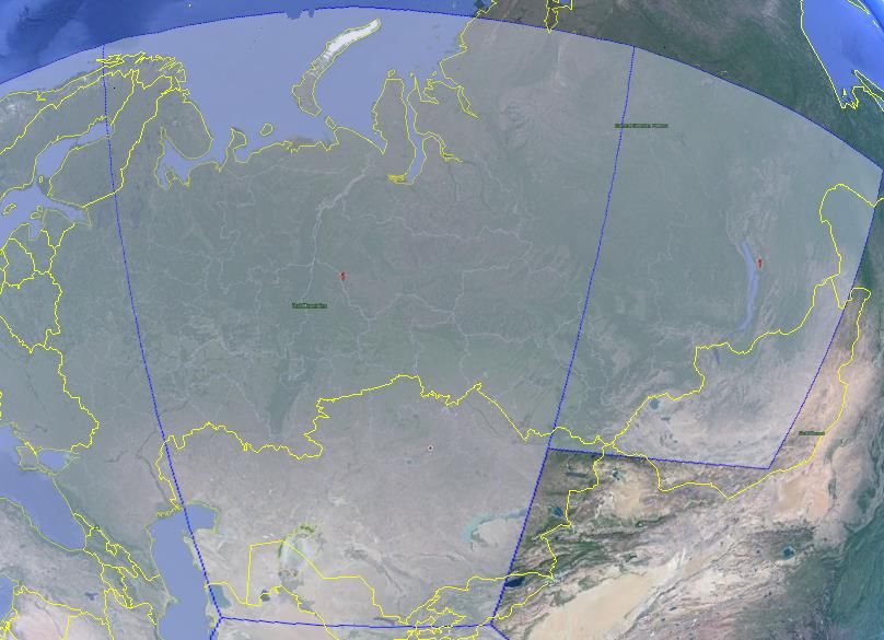
Coverage map .................................................................................................. 56
Operation in the MEAS footprint ................................................................. 57
Operation in the Russian Federation ........................................................... 59
Pointing the ODU ............................................................................................. 60
LED flow chart .................................................................................................. 62
Adjusting the azimuth and elevation of the ODU .............................................. 63
Exit pointing mode ........................................................................................... 64
Chapter 5
Lightning protection and safety ........................................................... 65
Lightning and grounding precautions / La foudre et la terre précautions .......... 65
Disclaimer / Avertissement............................................................................... 66
Chapter 6
AT unsolicited response codes.............................................................. 67
Chapter 7
Troubleshooting.................................................................................... 71
PDP context activation errors ........................................................................... 72
Chapter 8
Regulatory notices................................................................................ 73
EU Declaration of Conformity........................................................................... 73
FCC compliance / Conformité FCC .................................................................... 73
IC compliance / Conformité IC .......................................................................... 73
EU WEEE (Waste Electrical and Electronic Equipment) directives ..................... 74
Contents
4 H64151 Revision B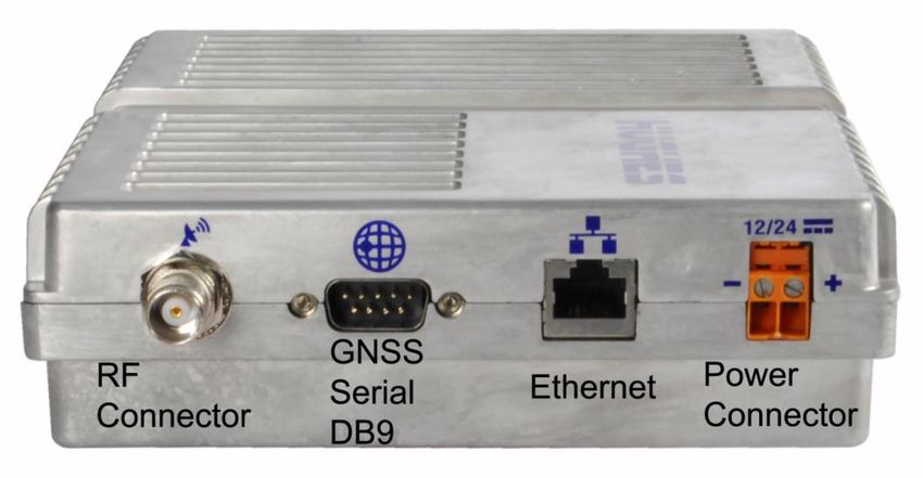
Understanding safety alert messages
               Safety alert messages call attention to potential safety hazards and tell you how to
               avoid them. These messages are identified by the signal words DANGER, WARNING,
               CAUTION, or NOTICE, as illustrated below. To avoid possible property damage,
               personal injury, or in some cases possible death, read and comply with all safety
               alert messages.
               Messages d'alerte de sécurité attirent l'attention sur les dangers potentiels et de
               vous dire comment les éviter. Ces messages sont identifiés par un signal mots
               DANGER, AVERTISSEMENT, ATTENTION, ou avis, comme illustré ci-dessous. Pour
               éviter des dommages matériels, des blessures ou la mort dans certains cas possible
               de lire et de respecter tous les messages d'alerte de sécurité.

Messages concerning personal injury / Messages concernant des
blessures corporelles
               The signal words DANGER, WARNING, and CAUTION indicate hazards that could
               result in personal injury or in some cases death, as explained below. Each of these
               signal words indicates the severity of the potential hazard.
               Le signal de DANGER mots, AVERTISSEMENT et ATTENTION indiquer les dangers qui
               pourraient entraîner des blessures ou, dans certains cas la mort, comme expliqué ci-
               dessous. Chacun de ces mots du signal indique la gravité du danger potentiel.

                  DANGER indicates a potentially hazardous situation which, if not avoided, will
                  result in death or serious injury.
                  DANGER indique une situation potentiellement dangereuse qui, si elle n'est pas
                  évitée, entraînera la mort ou des blessures graves.

                  WARNING indicates a potentially hazardous situation which, if not avoided,
                  could result in serious injury.
                  AVERTISSEMENT indique une situation potentiellement dangereuse qui, si elle
                  n'est pas évitée, pourrait entraîner des blessures graves.

                                                           Understanding safety alert messages
                                                                            H64151 Revision B
                                                                                                      5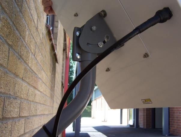
CAUTION indicates a potentially hazardous situation which, if not avoided,
                             could result in minor or moderate injury.
                             ATTENTION indique une situation potentiellement dangereuse qui, si elle n'est
                             pas évitée, pourrait entraîner des blessures mineures ou modérées.

    Messages concerning property damage / Messages concernant
    des dommages matériels
                          A NOTICE concerns property damage only.

                             NOTICE is used for advisory messages concerning possible property damage,
                             product damage or malfunction, data loss, or other unwanted results—but not
                             personal injury.
                             AVIS est utilisée pour les messages concernant les dommages matériels, des
                             dommages au produit ou de dysfonctionnement, de perte de données ou
                             d'autres résultats indésirables, mais des blessures non personnelle.

    Safety symbols
                          The generic safety alert symbol

                          calls attention to a potential personal injury hazard. It appears next to the DANGER,
                          WARNING, and CAUTION signal words as part of the signal word label. Other
                          symbols may appear next to DANGER, WARNING, or CAUTION to indicate a specific
                          type of hazard (for example, fire or electric shock). If other hazard symbols are used
                          in this document they are identified in this section.
                          Le symbole générique d'alerte suivant

                          attire l'attention sur un danger potentiel de risque de blessures. Il apparaît à côté
                          des mots DANGER, AVERTISSEMENT et ATTENTION dans le cadre de l'affichage
                          d’alerte. D'autres symboles peuvent apparaître à côté de DANGER, AVERTISSEMENT
                          ou ATTENTION pour indiquer un type spécifique de danger (par exemple, un incendie
                          ou un choc électrique). Si d’autres symboles de danger sont utilisés dans ce
                          document, ils sont décrits dans cette section.

    Understanding safety alert messages
6   H64151 Revision B
Additional symbols / Symboles supplémentaires
                        Warning Potential Radio Frequency (RF) hazard. Where you
                        see this alert symbol and WARNING heading, strictly follow
                        the warning instructions to avoid injury to eyes or other
                        personal injury.
                               Avertissement Danger possible de Fréquence Radio (RF). A la
                               vue de ce symbole d’alerte et du terme AVERTISSEMENT,
                               suivez rigoureusement les instructions d'avertissement afin
                               d’éviter une blessure aux yeux ou toute autre blessure.

                               Warning Where you see this alert symbol and WARNING
                               heading, strictly follow the warning instructions to avoid
                               personal injury.
                               Avertissement A la vue de ce symbole d’alerte et du terme
                               AVERTISSEMENT, suivez rigoureusement les instructions
                               d'avertissement pour éviter toute blessure.

                               Danger Electric shock hazard: Where you see this alert
                               symbol and DANGER heading, strictly follow the warning
                               instructions to avoid electric shock injury or death.
                               Danger Risque de choc électrique: A la vue de ce symbole
                               d’alerte et du terme DANGER, suivez rigoureusement les
                               instructions d'avertissement pour éviter tout choc électrique
                               ou blessure mortelle.

Warnings for satellite terminal / Avertissements pour le terminal satellite
                           Do not stand in front of the ODU (Antenna) This device emits
                           radio frequency energy. To avoid injury, do not place head or
                           other body parts in front of the satellite ODU when system is
                           operational. Maintain a distance of 1 m or more from the
                           front of the Satellite Terminal ODU.
                               Ne pas se tenir en face de l'ODU (antenne) Cet appareil émet
                               une énergie de fréquence radio. Pour éviter toute blessure, ne
                               placez pas la tête ou toute autre partie du corps en face de
                               l'ODU satellite lorsque le système est opérationnel. Maintenez
                               une distance de 1 m ou plus par rapport à l’ODU du terminal
                               satellite.

                               General Handle your Satellite Terminal with care. Avoid
                               exposing your Satellite Terminal to extreme hot or cold
                               temperatures outside the range -40ºC to +75ºC.

                                                      Understanding safety alert messages
                                                                       H64151 Revision B
                                                                                                7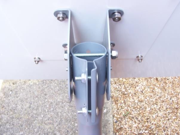
Avoid placing the Terminal close to cigarettes, open flames or
                                          any source of heat.
                                          Changes or modifications to the Terminal not expressly
                                          approved by Hughes Network Systems will void the Warranty
                                          and could void your authority to operate this equipment.
                                          Only use a soft damp cloth to clean the Terminal.
                                          To avoid impaired Terminal performance, please ensure the
                                          unit’s ODU is not damaged or covered with foreign material
                                          like paint or labeling.
                                          When inserting the SIM, do not bend it or damage the
                                          contacts in any way. When connecting the interface cables,
                                          do not use excessive force.
                                          Général Manipulez votre terminal satellite avec soin. Évitez
                                          d'exposer votre terminal satellite à des températures
                                          extrêmement chaudes ou froides en dehors de la plage -40 º C
                                          à 75 º C.
                                          Évitez de placer le terminal à proximité de la cigarette, de
                                          flammes nues ou de toute source de chaleur.
                                          Les changements ou modifications apportées au Terminal et
                                          non expressément approuvées par Hughes Network Systems
                                          annulent la garantie et peuvent annuler votre droit à utiliser
                                          cet équipement.
                                          Utilisez uniquement un chiffon doux humide pour nettoyer le
                                          terminal.
                                          Pour éviter toute dégradation des performances du terminal,
                                          veuillez vous assurer que l’ODU de l'unité n'est pas
                                          endommagée ou recouverte d’un corps étranger, comme de
                                          la peinture ou de l'étiquetage.
                                          Lorsque vous insérez la carte SIM, ne pas la plier ni
                                          endommager les contacts en aucune manière. Ne pas forcer
                                          lors de la connexion des câbles d’interface.

    Understanding safety alert messages
8   H64151 Revision B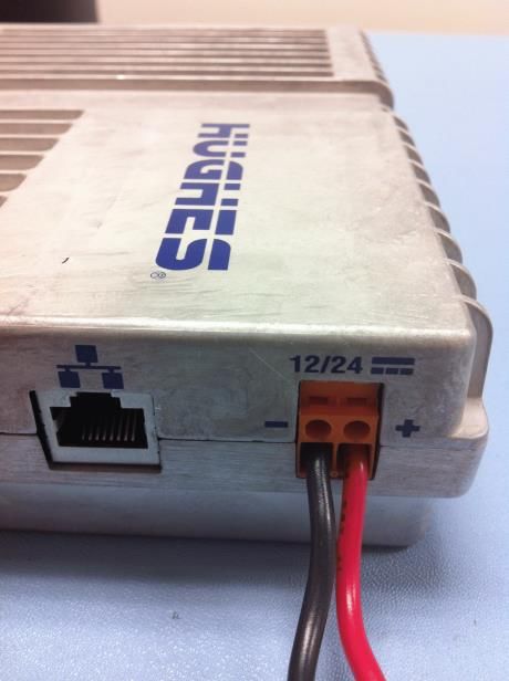
In the vicinity of blasting work and in explosive
environments Never use the Satellite Terminal where
blasting work is in progress. Observe all restrictions and
follow any regulations or rules. Areas with a potentially
explosive environment are often, but not always, clearly
marked.
A proximité de travaux de dynamitage et d’environnements
explosifs N'utilisez jamais le terminal satellite près de travaux
de dynamitage en cours. Respectez toutes les restrictions et
suivez toutes les instructions ou la règlementation. Les zones
présentant une atmosphère potentiellement explosive sont
généralement, mais pas toujours, clairement signalées.

Qualified Service Do not attempt to disassemble your
Satellite Terminal. The unit does not contain consumer-
serviceable components. Only qualified service personnel
may install or repair equipment.
Service Qualifié N'essayez pas de démonter votre terminal
satellite. L'unité ne contient pas de composants réparables
par le consommateur. Seul le personnel qualifié peut installer
ou réparer le matériel.

Accessories Use Hughes approved accessories only. Use of
non-approved accessories may result in loss of performance,
damage to the Satellite Terminal, fire, electric shock or injury.
Accessoires Utilisez uniquement des accessoires approuvés
par Hughes. L’utilisation d’accessoires non approuvés peut
entraîner une dégradation de performance, un
endommagement du terminal satellite, un incendie, une
électrocution ou des blessures.

Connecting Devices Never connect incompatible devices to
the Satellite Terminal. When connecting the Satellite
Terminal to any other device, read the device’s User Manual
for detailed safety instructions.
Connexion de périphériques Ne jamais connecter des
périphériques incompatibles au terminal satellite. Lors du
raccordement du terminal satellite à un autre appareil, lire le
manuel utilisateur du périphérique pour les instructions
détaillées de sécurité.

                       Understanding safety alert messages
                                        H64151 Revision B
                                                                    9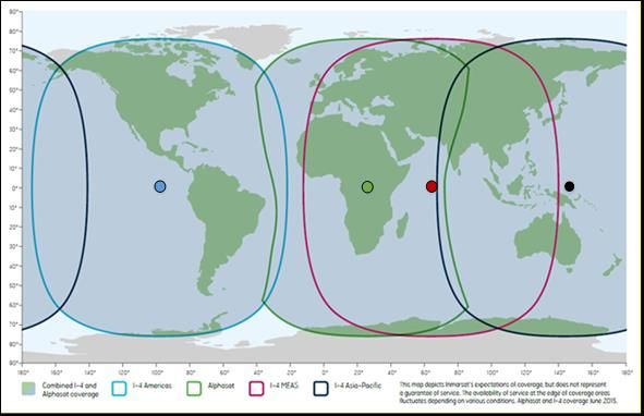
Pacemakers The various brands and models of cardiac
                                           pacemakers available exhibit a wide range of immunity levels
                                           to radio signals. Therefore, people who wear a cardiac
                                           pacemaker and who want to use a Satellite Terminal should
                                           seek the advice of their cardiologist. If, as a pacemaker user,
                                           you are still concerned about interaction with the Satellite
                                           Terminal, we suggest you follow these guidelines:
                                            •    Maintain a distance of one meter from the front and
                                                 sides of the ODU and your pacemaker;
                                            •    Refer to your pacemaker product literature for
                                                 information on your particular device.

                                           If you have any reason to suspect that interference is taking
                                           place, turn off your Satellite Terminal immediately.
                                           Stimulateurs Cardiaques Les différentes marques et modèles
                                           de stimulateurs cardiaques disponibles présentent un large
                                           éventail de niveaux d'immunité aux signaux radio. Par
                                           conséquent, les personnes qui portent un stimulateur
                                           cardiaque et qui veulent utiliser un terminal satellite doivent
                                           demander l'avis de leur cardiologue. Si, en tant qu'utilisateur
                                           de stimulateur cardiaque, vous êtes toujours soucieux d’une
                                           éventuelle interaction avec le terminal satellite, nous vous
                                           suggérons de suivre ces directives:
                                            •    Maintenez un mètre de distance entre votre
                                                 stimulateur cardiaque et l'avant ou les côtés de
                                                 l'ODU;
                                            •    Reportez-vous à la documentation de votre
                                                 stimulateur cardiaque pour toute information
                                                 spécifique à celui-ci.

                                           Si vous avez un doute que des interférences se produisent,
                                           éteignez votre terminal satellite immédiatement.

                                           Hearing Aids Most new models of hearing aids are immune
                                           to radio frequency interference from Satellite Terminals that
                                           are more than 2 meters away. Many types of older hearing
                                           aids may be susceptible to interference, making it very
                                           difficult to use them near a Terminal. Should interference be
                                           experienced, maintain additional separation between you
                                           and the Satellite Terminal.
                                           Appareils Auditifs La plupart des nouveaux appareils auditifs
                                           sont insensibles aux interférences dues aux fréquences radio
                                           des terminaux satellites situés à plus de 2 m . De nombreux
                                           modèles plus anciens peuvent être sensibles aux
                                           interférences, ce qui les rend très difficiles à utiliser à

     Understanding safety alert messages
10   H64151 Revision B
proximité d’un terminal. En cas d’interférences détectées,
veuillez maintenir une distance supplémentaire entre vous et
le terminal.
Electrical Storms installation of the Satellite Terminal during
electrical storms may result in severe personal injury or
death.
Orages Electriques L’installation d’un terminal satellite
pendant un orage électrique peut entrainer des blessures
graves ou mortelles.
Protective Earth Grounding is recommended by Hughes for
both the IDU and the ODU equipment. Please consult
professional local advice for these requirements.
Une mise à la terre de protection est recommandée par
Hughes à la fois pour l'IDU et le matériel ODU. Veuillez
consulter un conseil professionnel local pour ces
spécifications.
Understanding safety alert messages
H64151 Revision B
11Understanding safety alert messages 12 H64151 Revision B
Chapter 1
                                         Product description
Contents of the Hughes 9502 kit
              The Hughes 9502 Kit (P/N 3500509-0001) is a two piece design that comes with an
              Indoor Unit (IDU), an Outdoor Unit (ODU) and a 10 meter RF cable that has an N
              type connection at both ends and an N to TNC adapter inside the cable bag for
              connection to the IDU.

                                      Figure 1: IDU P/N 3500563-0001

                         Figure 2: RF cable with N to TNC adapter P/N 3500634-0001

                                      Figure 3: ODU P/N 3500564-0001

                                                             Chapter 1 • Product description
                                                                         H64151 Revision B      13
Optional mounting accessories
The IDU can be mounted using the IDU strap (P/N 3500617-0001) if desired. Strap
will require 4 each mounting bolts either M3.5 or 6/32” (not included).
Figure 4: IDU mounting strap
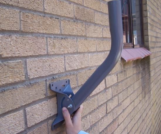
The ODU can be mounted using the Basic Fixed Mount Kit (P/N 3004066-0002) or by
using the azimuth elevation bracket (P/N 1022994-0022) and an existing 1.5”
diameter pole.
Figure 5: Azimuth/Elevation bracket
Main features of the 9502
The main features of the Hughes 9502 terminal are listed below:
• Use of Internet Protocol (IP) via the BGAN satellite network
• Remote Management
— Web UI interface
— SMS Control
— AT Command Control
— Log file upload
— Terminal configuration
— Remote firmware upgrade
• Power Savings and Sleep Mode
• IP Watchdog
• Install Mode
• XL-band ready
• NAT, NAPT, Relay and PPPoE Modes
• Auto Power ON when power is applied
Chapter 1 • Product description
14 H64151 Revision B• Automatic PDP Context Activation (Static or DHCP)
• Dedicated M2M web UI
• Security
— Ethernet MAC Filtering
— Administration Password
— SMS Control password
— White List for SMS control
— AT Command password lock
— SIM Personalization
• Phone-to-SIM
• DP SIM Lock
• SP SIM Lock
Interfaces
The Hughes 9502 has the following interfaces:
• Ethernet connection (RJ45)
• USB 1.1 connection (USB Type-B) for PC to configure terminal (requires
installation of Hughes USB driver. See www.bgan.hughes.com)
• TNC type RF connector on IDU and N-type RF connector on the ODU
• Integrated GPS receiver and L-band ODU
• RS232 serial interface (DB9 male, DTE) to external NMEA 0183 based GNSS
device (e.g., GLONASS receiver). This port cannot be used for serial data.
• 3 LED status display and a single function button
• 3.5 mm stereo audio jack for audio tone or voltage level to assist in ODU
pointing
• USIM card slot behind SIM door
Figure 6: Front side view of IDU
Chapter 1 • Product description
H64151 Revision B 15Figure 7: Back side view of IDU
Chapter 1 • Product description
16 H64151 Revision BTerminal specifications
Table 1: Terminal specifications
Technical Specifications
Satellite TX Frequency @ 1626.5 – 1675MHz
Satellite RX Frequency @ 1518 – 1559 MHz
GPS Frequency @ 1574.42 – 1576.42 MHz
9502 Indoor Unit Weight: 1.12 Kg
9502 Indoor Unit Dimensions: 150 mm x 200 mm x 45 mm
9502 External Antenna Weight: 1.85 Kg (exclude mount and cable)
9502 External Antenna Dimensions: 385 mm x 385 mm x 33 mm
Operating Temperature -40oC to +75oC
Storage Temperature -55oC to +75oC
Humidity 95% RH at +40oC
9502 External Antenna Wind loading Survival wind loading (with optional mount) up to 100 mph
9502 Indoor Unit Water and Dust IP-40 Compliant
9502 External Antenna Water and Dust IP-65 Compliant
Nominal Input Voltage and Max Current +12VDC / +24VDC 1.5A / 0.75A
Minimum/Maximum input voltage +10.8VDC / +26.4VDC
Data Connectivity: RJ45 connector (Ethernet 10BaseT)
USB –Type B (USB 1.1 for configuration PC)
Other Features:
Single external BGAN Satellite and GPS antenna connection
GPS module inside Indoor Unit
3 status LEDs
Antenna pointing audio tone and voltage level indicator
through audio jack
SIM/USIM Slot (behind SIM door)
Chapter 1 • Product description
H64151 Revision B 17Information for maintenance
In the event that a Hughes 9502 terminal develops a problem, please follow the
instructions below.
For users:
Please contact the company that you purchased the Hughes 9502 terminal from so
that they can request an RMA from Hughes for your terminal.
For distribution providers:
Should a Hughes 9502 terminal need to be returned for repair, an RMA will be
required.
• To request an RMA access the Customer Care Portal at
https://customergateway.hns.com
• Alternatively, an RMA may be requested via Email to MRC@hns.com
• Ship the unit to the Hughes repair center at the following address; be sure to
include the RMA number on the address label.
Hughes Network Systems
Attn: RMA # XXXXXXXXX
Material Return Center
16060 Industrial Drive
Gaithersburg, MD 20877
USA
Date of manufacture
If it is necessary to determine the date of manufacture of a unit, e-mail Hughes at
MobileSatelliteSupport@Hughes.com and provide the IMEI from the unit label.
Manufacturer contact
For other general queries, contact Hughes at:
11717 Exploration Lane, Germantown, MD 20876, USA
+1 (301) 428-5500
www.hughes.com
Chapter 1 • Product description
18 H64151 Revision BChapter 2
Configuration via Web UI
The UT is typically configured via the Web User Interface (UI). Browsers that are
currently supported are IE, Edge, Firefox, and Safari. Release 5.9.6.1 adds full
support for the Chrome browser.
Web UI layout
The Web User Interface (UI) can be accessed from a MAC or PC browser by entering
192.168.128.100 as the URL (unless you change the IP address of the UT.)
Table 2 shows the 9502 Web UI layout:
Table 2: 9502 Web UI layout
Home Connections Settings M2M Security SMS
Home Manage Contexts General M2M Setup Security Send/Receive SMS
Automatic Contexts IP Address / DHCP Saved Drafts
Manage APNs Ethernet Sent Messages
ATC Setup
Features
Home tab
The home page includes the following fields:
Terminal Information
• Model, IMEI, Software Version
SIM Information
• IMSI, SIM APN, Terminal phone number
Troubleshooting
Terminal Log Files: This allows you to extract and save any of the following log files
for troubleshooting purposes:
• System Log
• Event Log
• Packet Log
Chapter 2 • Configuration via Web UI
H64151 Revision B 19These files can be FTPed out of the UT and used for debugging. To download the
logs right-click on the “Download Current” link and select “Save Target As”. This
uses FTP to retrieve the files from the UT which can be blocked by some security
software such as McAfee. If you encounter problems, check your PC security
settings.
When extracting files, clear the browser cache on the computer between each
download or the browser may use a cached copy rather than downloading the
latest version of the file. It is also best to save the file to a unique name including a
time stamp.
Release 5.9.6.1 adds support for downloading files with the Chrome browser. It also
adds a timestamp to the file name to avoid the caching problem mentioned above.
Figure 8: Home Page
Chapter 2 • Configuration via Web UI
20 H64151 Revision BReset Terminal to Factory Defaults: Clicking the “Restore to Defaults” button will
restore the UT back to the factory default settings and delete any of the user
parameters that have been set-up in the UT, including any custom APN settings.
In Release 5.9.6.1 and above you can also Reset to Factory Defaults if the small blue
button next to the SIM card holder is depressed while powering off. Press and hold
the blue button and then press and hold the function button for three seconds until
the LEDs flash. Then release both buttons. Note this function is blocked if enhanced
security is active.
Reboot Terminal: Clicking this button reboots the terminal so that configuration
changes can be saved into the configuration file, or it can be clicked when just a
simple reboot of the terminal is required.
Status bar
The status bar is included on the home page and other pages that do not have a
navigation bar. It includes a field with the elevation angle and compass direction
towards the visible satellite(s).
Chapter 2 • Configuration via Web UI
H64151 Revision B 21The status text in the Connection section is as shown in Table 3 below.
Table 3: Status bar
Display Comments Corresponding LED
display
Initializing Initial startup (~15-20 secs) Various
Pointing UT in pointing mode All three LEDs flash 1Hz
Registering Attempting to register - pointing PWR on, GPS on or flashing,
mode exited or bypassed NET off
Registered Registered and attached, no PWR on, GPS on and NET
context flashing
Connected PDP context active All three on (or off after 1
minute timeout)
The signal strength bar shows the quality of the received signal. It also lists the
current satellite beam type, beam number and the current satellite. The signal
strength increases in value as the UT transitions to the Regional Beam and again
when it gets a PDP context and transitions to the Narrow Beam.
Typical signal levels for the 9502:
Global beam, during pointing: 50 – 55 dB
Regional beam, during registration or idle: 57 – 61 dB
Narrow beam, on a data channel: 65 – 70 dB
The GPS status area shows the status of the GPS fix and results are shown in the
following table:
Table 4: GPS status
Display Comments
Acquiring Trying to acquire a GPS fix
Stored UT is using a Stored GPS fix
2D GPS Fix The UT has acquired a 2D GPS fix and can continue Registration
with the network
3D GPS Fix The UT has acquired a 3D Fix
GNSS Fix The UT got a fix from a GNSS device connected to the serial port.
Location Shows Latitude and Longitude coordinates if allowed by network
GPS Policy.
Shows “Waiting” if the unit has a fix but the policy has not yet
been received from the network.
Last Fix Shows date and UTC time of last GPS fix
The Pointing Info section shows the satellite that the UT should be pointed to and
the Azimuth and elevation angles to the satellite. When the UT is in an overlap
region, all visible satellites are shown and the user can pick the best one.
Chapter 2 • Configuration via Web UI
22 H64151 Revision BIn release 5.9.5.0 and above, a pointing control button was added to the Home page
that duplicates the function button on the UT. During the “wait for input” state at
startup this button is active for 15 seconds. If pressed the UT will enter pointing
mode and remain until the button is pressed again. This feature is useful for
repointing one piece 9502s without opening the enclosure.
Figure 9: Enter pointing
Chapter 2 • Configuration via Web UI
H64151 Revision B 23Connections tab
Manage contexts page
The Manage Contexts page under the Connections tab displays the status of any
active contexts and allows contexts to be controlled. Typically this page will not be
used and you configure context activation via the always on option on the M2M
page, or the ACA page.
Note: In NAPT mode the PDP context will NAPT data for all devices on the LAN. The
owner IP address is shown as “shared”.
Figure 10: Manage contexts
Chapter 2 • Configuration via Web UI
24 H64151 Revision BAutomatic contexts
This web page allows you to use Automatic Context Activation (ACA) for multiple
devices. (The M2M page Always on context can be used if you only require a single
context). The ACA page is not available in NAPT or PPPoE modes.
Static IP Automatic Contexts: You can define static ACA entries for specific
addresses. If an entry is set to “On”, the UT will set up a context for this address at
startup, regardless of whether it sees it. If set to “Data”, the UT will activate the
context when it sees data from the device destined to the space link.
If the context is deactivated by the network, e.g. due to inactivity, the UT will
reactivate it.
To turn on ACA for a particular static address, select “On” or “Data” from the drop
down list and enter an address.
When you are finished, click on Update Static Settings and you should see a
message saying “Operation Successful”.
Figure 11: Automatic contexts
Chapter 2 • Configuration via Web UI
H64151 Revision B 25DHCP Automatic Contexts: This option allows you to set up the UT for dynamic
ACA. This means that any device connected to the UT via DHCP will automatically
receive a standard context.
To activate this feature, select “On” or “Data” from the drop down list under DHCP
Automatic Contexts section. The APN will be the default APN configured on the
Manage APNs page.
Figure 12: Automatic contexts
Once you hit “Apply” you will get a pop-up message saying that the ACA settings
were updated successfully and to take effect you will have to reboot the terminal.
Once you reboot the terminal, check that the settings took effect.
To see if the context has been setup properly, click on the Connections tab>Manage
Contexts Page and this will show you all contexts that have been setup (active or
inactive).
Chapter 2 • Configuration via Web UI
26 H64151 Revision BManage APNs page
The Manage APNs page under the Connections tab allows the user to view the
available APNs and define new ones, e.g. if the correct APN is not configured in the
SIM.
To make an APN the default, select it in the Defined APNs list and press “Make
Default”. The selected APN will be moved to the top of the list and shown in bold
font. If an Always on Context is already defined, you must manually update the
configuration on the M2M page to change to the new APN.
Figure 13: Manage APNs
Add an APN field – Use this field to add an additional APN that you want to use, or
to edit an existing APN. For adding a new APN, type in the new APN and username
(if required) then select Add New APN. If the APN requires a password, select the
“APN Requires Password” box. If you want to save the password so you don’t have
to re-type it each time you configure a PDP context for that APN, check the
“Remember my Password” box and then click the Add New APN button. (The
username is always saved if entered.) The new APN name will show up in the
Defined APNs field with the username in parentheses. This APN will now be
available to use from any APN drop down menu.
Chapter 2 • Configuration via Web UI
H64151 Revision B 27Settings tab
The settings tab has the following configuration pages:
General setup
Release 5.9.5.0 on includes a General Setup page with the following fields:
• Connection: this field controls the satellites the UT will try to connect to.
With the default “Automatic” selection it will search for all satellites.
• If an individual satellite is selected the UT will only search for and use the
selected satellite. This is useful in areas where the antenna can see two
satellites at the same time, e.g. EMEA and MEAS from Europe and West
Africa – see Figure 39 on page 58. During site switches, the satellite signal is
turned off briefly and the UT may try to register on the other satellite it can
see. The signal will be weaker and will degrade service, so it is advisable to
configure the UT to only use a single satellite. The visible satellites are shown
on the status bar of the Home page.
• Streaming Inactivity Timer. In 9502B (BGAN Services) mode, a streaming
inactivity timer field is also displayed. By enabling this parameter, the user
can turn on a timer for inactivity on streaming contexts. The timer is in
either seconds or minutes and will tear down a streaming context after X
seconds or minutes of inactivity.
Figure 14: General Setup
Chapter 2 • Configuration via Web UI
28 H64151 Revision BIP Address/DHCP Settings
The IP settings page under the Settings tab includes the following fields:
• Terminal Local IP address
— Allows you to change the UT’s IP address
— In PPPoE mode with the Inmarsat NSD you typically set the UT IP address
to 192.168.0.1. If two BGAN terminals are connected to the NSD, set the IP
address of the second UT to 192.168.0.129.
• Subnet Mask Range (release 5.9.5.3 and higher)
— Only used in PPPoE mode. If two BGAN terminals are connected to the
NSD, set to 255.255.255.128
• Default route IP address (release 5.9.5.3 and higher)
— Only used in PPPoE mode. Use with the NSD when the TE local subnet is
different from the UT subnet.
• DHCP Server enable
• DHCP Address Range
• Lease Time when Idle
• Lease Time when Connected
— If operating with a Vodafone MachineLink, recommend setting to a large
value such as 1440 minutes, or use Static addressing.
• Network Mode field: NAT, NAPT, Relay or PPPoE mode (see Network mode
on page 41.)
• Relay Connected Mode Subnet Mask (release 5.9.5.3 and higher)
— Defaults to 255.255.0.0. Can be used to configure a different subnet mask
in Relay mode. Only applied when the Relay mode PDP context is active.
Figure 15: IP address/DHCP settings
Chapter 2 • Configuration via Web UI
H64151 Revision B 29Ethernet Port page
The Ethernet Port settings page includes:
• Wake On LAN (see Wake on LAN (any packet) on page 44):
— Wake On LAN – On/Off radio button
— Wake On LAN idle timer – in minutes
— Wake On LAN time of day – 24 hour clock
• MAC Address filtering:
— Ethernet MAC Address filtering enable tick box
— Table of allowed Ethernet MAC addresses.
• Ethernet Operation: Duplex Mode
— In Default mode, the UT uses Half Duplex, except in Netmode PPPoE when
it automatically uses Full Duplex for operation with the Inmarsat NSD.
— Full or Half Duplex option can be used in the unusual case that the default
setting is not correct for your application.
Note that the UT does not support duplex negotiation and so Full Duplex
can only be used in the rare case that the TE device is also configured for
Full Duplex, no negotiation.
Figure 16: Ethernet Settings
Chapter 2 • Configuration via Web UI
30 H64151 Revision BPort Forwarding page
The Port Forwarding page is only available in NAPT mode and includes:
• DMZ – if enabled, all packets received from the space link that are not routed
to other addresses will be forwarded to the DMZ host address.
• Port Forwarding Rules. These fields allow you to configure rules defining how
packets of particular protocols are routed, e.g. TCP port 80 for HTTP. Port
Forwarding rules are applied before the DMZ rule.
Figure 17: Port Forwarding settings
Chapter 2 • Configuration via Web UI
H64151 Revision B 31ATC page
The ATC page includes:
• ATC robustness On/Off radio button
• ATC scan button
• ATC scan status bar. This indicates the results of the last scan.
Figure 18: ATC page
Chapter 2 • Configuration via Web UI
32 H64151 Revision BFeature Management page
You can enable special features from this page:
SMS Remote Management allows the unit to receive and act on special remote
control SMS messages. This feature is on by default.
Enhanced Security allows you to lock the UT so that it can only be accessed locally
after entering a password. Refer to the Enhanced Security Settings page below
(page 37). When this feature is active, the remote SMS password will be stored
encrypted. When the feature is enabled a link to the Enhanced Security page
appears on the Security Passwords page (see below—page 36).
BGAN Services allows the unit to be converted to a unit that uses a BGAN SIM
rather than an M2M SIM.
With release 5.9.5.1 and above, the UT will automatically switch between M2M and
BGAN Services based on the type of SIM card. The Feature code is no longer
required.
In release 5.9.6.1 and above, Enhanced Security can be enabled and disabled
without a feature code. Simply select the required option and press “Act/Deact
Feature”.
Figure 19: Feature management page
Chapter 2 • Configuration via Web UI
H64151 Revision B 33M2M page
Figure 20: M2M Setup
The M2M page includes the following configurable parameters:
Ping configuration:
• Context Watchdog - On/Off. The watchdog can be used to periodically verify
the UT network connectivity and take recovery action if a problem is
detected.
• Primary Ping Address – enter an address pingable by the UT over the
spacelink.
• Secondary Ping Address. If you don’t have a secondary address, you can
configure the primary address in this field to give the UT more attempts to
reach the server.
• Tertiary Ping Address
• Time between Pings. If the connected device sends or receives data on a
periodic basis, set this time to be longer than the periodicity of the data.
• Ping required - Yes/No. If set to “No”, the system will not try to ping on timer
expiration if data was transmitted within the watchdog period. This is the
recommended setting. If set to “Yes”, the system will always ping when the
“Time between Pings” expires, which will cause extra data to be sent on the
link.
Chapter 2 • Configuration via Web UI
34 H64151 Revision BAlways on context:
• Always on context - On/Off (default is On)
• Always on static IP address. If the TE has a known static IP address or never
ARPs, enter this address. Alternatively, leave the IP address blank (0.0.0.0)
and the UT will set up a context for the first device it detects through ARP
during startup.
• APN drop down box. This includes the APNs configured on the Manage APNs
page and (in release 5.9.5.2 and above) the “Use a network assigned APN”
option. This option allows the network to assign the APN rather than the user
configuring it at the UT. It should only be used if this option is appropriately
configured at the network side.
Chapter 2 • Configuration via Web UI
H64151 Revision B 35Security Passwords
The security passwords page includes the following functions:
• Personalization Key to lock the UT to a particular USIM (SIM to Phone lock).
This is Off by default.
• Administration password – Off by default. Default password is admin
• SMS Remote Control – Off by default except in releases 5.9.4.3 through
5.9.5.3 where it is On by default.
• SMS Remote Password – default was remote but in 5.9.6.1 and above the
default is blank and a password must be entered when enabling SMS Remote
Control.
• Sender White-list – is a list of numbers that the terminal will allow a remote
SMS message to come from. When entering the number use the + symbol in
front of the country code e.g., +870 or just start with the country code e.g.,
870. Do not use 00 in front of the country code.
Figure 21: Security Passwords
Chapter 2 • Configuration via Web UI
36 H64151 Revision BIf the Enhanced Security feature is enabled, a link to the Enhanced Security page will
be displayed as shown below.
Figure 22: Enhanced Security Page Link
Enhanced Security Settings page
The Enhanced Security Page is used to configure local security for the unit.
Figure 23: Enhanced Security Settings page
For added security you can lock the UT so that it cannot be accessed locally. This is
controlled by a security password configured from the Enhanced Security Settings
page accessible from the Security Passwords page.
When the password is active, each time the UT starts up, the password must be
entered before the user interface can be accessed. All local IP ports are blocked, e.g.
so AT commands, and the upgrader cannot be used. User data can be sent if a PDP
context is up.
Chapter 2 • Configuration via Web UI
H64151 Revision B 37To activate the security feature, select “Password Protection” On, enter the same
password string in both fields and press “Apply”. If the two password fields match,
the password is saved and security is enabled.
The UT will be locked when it restarts, or to immediately lock it, press “Lock Unit”
Make a note of the password as it cannot be viewed and once the UT is locked it
cannot be accessed.
To deactivate the security feature, select “Password Protection” Off and press
“Apply”.
If the Web UI is accessed when the UT is locked, the browser is redirected to the
Login page and the password must be entered. If the wrong password is entered
three times in a row, password entry is locked out and the UT must be restarted
before the password will be accepted.
Figure 24: Login Page
Chapter 2 • Configuration via Web UI
38 H64151 Revision BSMS pages
The SMS pages are used to send SMS messages from the terminal to another BGAN
device or another phone number. When sending an SMS message, use the +
symbol in front of the country code of the number you want to send the SMS to
e.g., +16199778619.
Figure 25: SMS send/receive
Chapter 2 • Configuration via Web UI
H64151 Revision B 39Chapter 2 • Configuration via Web UI 40 H64151 Revision B
Chapter 3
                                          Operational features
LEDs
               The 9502 has three green LEDs:
                  •   Power LED: “PWR”
                      — Turn unit on - LED turns on
                  •   “GPS” LED
                      — Flashes while acquiring fix
                      — Turns solid when unit has a 2D or 3D fix
                  •   Network LED: “NET”
                      — Flashes when registered
                      — Turns solid when unit establishes a PDP context
               All three LEDs flash in install mode and short flash if there is a fault detected that
               prevents normal operation, e.g. no SIM installed, or incorrect SIM installed.

Function button
               The M2M unit includes one user button called the “function” button.
                  •   Short press (< 2 second):
                      — During startup while power LED flashing, a short press enters install mode
                        (see Pg 55.)
                      — In install mode, short press exits install mode
                      — If LEDs off, short press turns them on
                  •   Medium press (2 to 5 seconds – the user should press and hold for about 3
                      seconds):
                      — Shut down and reboot
                  •   Long press (> 5 seconds):
                      — Hardware power cycle

Network mode
               By default the 9502 is configured for NAT mode in the Network Mode field on the IP
               Address/DHCP settings page.

       NAT mode
               In NAT mode once a PDP context is active, the UT will translate between the local
               and global IP addresses. This is a basic NAT that only performs IP address
               translation. It does not use port translation.

                                                                  Chapter 3 • Operational features
                                                                               H64151 Revision B        41
NAPT mode
In NAPT mode (5.9.4.4 and above) multiple devices connected via a hub or switch
share a single PDP context. The port translating NAT modifies both IP addresses and
port numbers so multiple devices can share the single global IP address assigned to
the PDP context.
In NAPT mode only a single context is supported. By default the Always On Context
is activated on the M2M page. The ACA page is removed. A Port Forwarding page is
added under Settings and can be used to configure the DMZ and Port Forwarding
rules.
Relay mode
In Relay mode the UT will supply the global IP address to the TE when the context is
established. Relay mode is single user and only supports a single connected TE.
In Relay mode DHCP is required to provide the global IP address to the TE. When
the context is activated, the DHCP server in the UT will NACK the next DHCP lease
renewal from the TE and assign the global IP address assigned by the network. The
local IP connection will be torn down and reestablished as the IP address changes.
Similarly, when the context is deactivated the DHCP server will NACK the lease
renewal and then reassign the original private IP address.
The Web UI will lose and reestablish its connection to the terminal as the IP address
is changed.
To make the IP address change happen quickly a short DHCP lease should be used.
The terminal defaults the lease time to 60 seconds in idle and connected mode.
Relay mode only supports a single user TE. If you need to connect a laptop via
the USB port for configuration and monitoring purposes, you must set the
laptop up with a local static IP address within the same subnet as the terminal
e.g., 192.168.128.200. This prevents the USB port from getting the single
DHCP address when in Relay mode once you reboot the terminal.
PPPoE mode
In PPPoE mode (release 5.9.5.3 and above) the UT uses PPP over Ethernet to
communicate with the TEs. PPP sessions are mapped to PDP contexts. PPPoE mode
is primarily designed to operate as a backup path for the Inmarsat Network Service
Device (NSD). Refer to the Inmarsat NSD documentation for details.
The NSD requires the UT to be configured for 10BaseT Full Duplex. When PPPoE
mode is selected, the UT will automatically set the Ethernet port to Full Duplex. If
PPPoE is used with another device not hard configured for full duplex, manually
select Half Duplex on the Ethernet Settings page.
With the NSD you typically set the UT IP address to 192.168.0.1 on the IP settings
page. If two BGAN terminals are connected to the NSD, set the subnet mask to
Chapter 3 • Operational features
42 H64151 Revision B255.255.255.128 on both UTs and set the IP address of the second UT to
192.168.0.129.
If the TEs use a subnet other than the directly connected interface range, configure
a default route on the IP Settings page so that the WebUI can be accessed. The
default route will be in the subnet associated with the TE Ethernet interface.
If you need to reconfigure a UT out of PPPoE mode back to NAT mode, it may be
easiest to first Reset Factory Defaults from the Home page.
Remote control
The 9502 can be controlled remotely via SMS and locally via AT commands. The AT
interface can be used for local control of the terminal as long as AT commands can
be sent by the terminal equipment (TE) connected. The AT command listing
supported by the 9502 can be downloaded from the Hughes website at
www.bgan.hughes.com .
The 9502 includes a remote control by SMS feature that supports the special SMS
messages listed in Table 5. Remote control SMS is supported by default in the 9502
and does not have to be activated by a feature code. The syntax of the messages is
covered in the “Hughes 9502 SMS Remote Control Feature User Guide.”
Table 5: Remote Control SMS Message Commands
Command Action
ACTIVATE Activate PDP context
DEACTIVATE Deactivate PDP context
CLEAR Clear SMS messages in the UT SIM
GETINFO Get info from the UT. This returns an SMS with the information.
RESTART Restart the UT
WATCHDOG Change the configuration of the watchdog parameters
ATCO Execute the AT command encapsulated in the SMS. This can be used for the
following remote control functions:
Download Firmware
Start Firmware upgrade
Get file
Send file, e.g. log files.
Activate Remote Web access
Perform ATC scan and/or set ATC robustness.
Configure the default APN (release 5.9.4.3 on)
Configure the satellite to use (release 5.9.5.0 on)
All remote control messages and responses must fit into a single 160 character SMS.
The SMS handler automatically deletes any message that fills the last SMS slot in the
USIM to ensure there is always room to receive control SMS messages. Control
messages are received into the SIM then read out and deleted so as not to fill up
the SIM card.
Chapter 3 • Operational features
H64151 Revision B 43Remote upgrade and file transfer
The 9502 includes an FTP client. The operator can send SMS messages or AT
commands to command the 9502 to send or retrieve files from an FTP server in the
network or Internet. This allows the 9502 to be upgraded, reconfigured and also
allows log files to be sent back to the server. The FTP server can be in the Inmarsat
network, e.g. accessible via a free APN for upgrades; or can be outside the Inmarsat
network, e.g. accessible via a normal APN for debugging and configuration changes.
The remote upgrade process uses download firmware and firmware upgrade
commands (see “Hughes 9502 SMS Remote Control Feature User Guide”).
Security
The Web UI includes an admin feature that can be activated from the security page
to prevent unauthorized access to the Web UI. Additionally the AT command port is
locked by default and the command: AT_ICLCK=”AD”,0,””
must be used to unlock it before AT commands can be used. Both mechanisms use
the same password but the AT commands port and each Web UI session use a
separate lock and must be individually unlocked.
Support for SMS Remote control is configured from the SMS settings page. Each
Remote Control SMS must include the correct password. Remote control SMS
containing AT commands will be processed regardless of the Admin setting (they
require the feature to be active and the correct SMS password.)
USIM personalization (or “Phone to SIM lock”) can be used to lock the UT to a
particular SIM.
MAC address filtering on the Ethernet port page allows the user to define the MAC
address of TEs authorized to communicate via the Ethernet port.
Note: The USB port is not included in the MAC filtering and can be used if the
proper USB driver is installed on the TE.
Wake on LAN (any packet)
The UT includes a special low power mode called Wake on LAN (any packet). From
the Web UI you can configure the UT to power down into this mode after a
configurable idle timer or time of day.
Wake on LAN operation is configured from the Ethernet Settings page (Figure 16 on
page 30) under the Settings tab. It includes a configurable idle timer to control
when the UT shuts down into the Wake on LAN mode. The UT declares the link idle
if no packets are received on the Ethernet port within the idle time.
Additionally, the UT can be configured to power down at a configurable time of day.
Enter UTC time as 0001 to 2400. Set to 0 to deactivate the time of day feature. Note
that the UT waits 5 minutes after startup before it checks the time of day to see if it
has to power off.
When the UT powers down into this mode it will disconnect from the BGAN
network and monitor the local Ethernet port and power up again if it sees any
Chapter 3 • Operational features
44 H64151 Revision BVous pouvez aussi lire