INSTALLATION GUIDE AXIS P3343-VE Network Camera AXIS P3344-VE Network Camera
←
→
Transcription du contenu de la page
Si votre navigateur ne rend pas la page correctement, lisez s'il vous plaît le contenu de la page ci-dessous
INSTALLATION GUIDE

AXIS P3343-VE Network Camera

                               ENGLISH
AXIS P3344-VE Network Camera

                               FRANÇAIS
                               DEUTSCH
                               ITALIANO
                               ESPAÑOL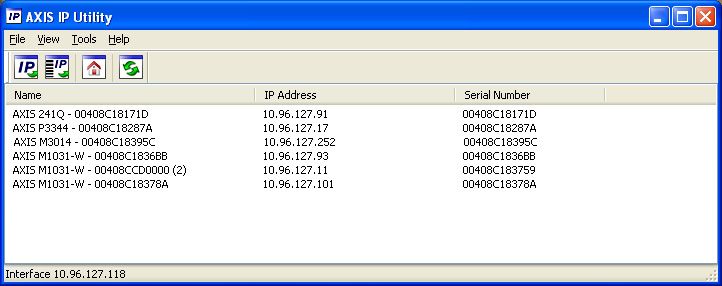
About this Document                                          Equipment Modifications
This document includes instructions for installing AXIS      This equipment must be installed and used in strict
P3343-VE and AXIS P3344-VE on your network. Previous         accordance with the instructions given in the user
experience of networking will be beneficial when             documentation. This equipment contains no
installing the product.                                      user-serviceable components. Unauthorized equipment
                                                             changes or modifications will invalidate all applicable
Legal Considerations                                         regulatory certifications and approvals.
Video and audio surveillance can be prohibited by laws
that vary from country to country. Check the laws in         Liability
your local region before using this product for              Every care has been taken in the preparation of this
surveillance purposes.                                       document. Please inform your local Axis office of any
This product includes one (1) H.264 decoder license. To      inaccuracies or omissions. Axis Communications AB
purchase further licenses, contact your reseller.            cannot be held responsible for any technical or
                                                             typographical errors and reserves the right to make
Electromagnetic Compatibility (EMC)                          changes to the product and documentation without
This equipment generates, uses and can radiate radio         prior notice. Axis Communications AB makes no
frequency energy and, if not installed and used in           warranty of any kind with regard to the material
accordance with the instructions, may cause harmful          contained within this document, including, but not
interference to radio communications. However, there is      limited to, the implied warranties of merchantability
no guarantee that interference will not occur in a           and fitness for a particular purpose. Axis
particular installation.                                     Communications AB shall not be liable nor responsible
                                                             for incidental or consequential damages in connection
If this equipment does cause harmful interference to         with the furnishing, performance or use of this material.
radio or television reception, which can be determined
by turning the equipment off and on, the user is             RoHS
encouraged to try to correct the interference by one or      This product complies with both the European
more of the following measures: Re-orient or relocate        RoHS directive, 2002/95/EC, and the Chinese
the receiving antenna. Increase the separation between       RoHS regulations, ACPEIP.
the equipment and receiver. Connect the equipment to
an outlet on a different circuit to the receiver. Consult    WEEE Directive
your dealer or an experienced radio/TV technician for        The European Union has enacted a Directive
help. Shielded (STP) network cables must be used with        2002/96/EC on Waste Electrical and Electronic
this unit to ensure compliance with EMC standards.           Equipment (WEEE Directive). This directive is
USA - This equipment has been tested and found to            applicable in the European Union member
comply with the limits for a Class B computing device        states.
pursuant to Subpart B of Part 15 of FCC rules, which are     The WEEE marking on this product (see right) or its
designed to provide reasonable protection against such       documentation indicates that the product must not be
interference when operated in a commercial                   disposed of together with household waste. To prevent
environment. Operation of this equipment in a                possible harm to human health and/or the environment,
residential area is likely to cause interference, in which   the product must be disposed of in an approved and
case the user at his/her own expense will be required to     environmentally safe recycling process. For further
take whatever measures may be required to correct the        information on how to dispose of this product correctly,
interference.                                                contact the product supplier, or the local authority
                                                             responsible for waste disposal in your area.
Canada - This Class B digital apparatus complies with        Business users should contact the product supplier for
Canadian ICES-003.                                           information on how to dispose of this product correctly.
                                                             This product should not be mixed with other commercial
Europe -       This digital equipment fulfills the           waste. For more information, visit
requirements for radiated emission according to limit B      www.axis.com/techsup/commercial waste
of EN55022, and the requirements for immunity
according to EN55024 residential and commercial              Support
industry.                                                    Should you require any technical assistance, please
Japan - This is a class B product based on the standard      contact your Axis reseller. If your questions cannot be
of the Voluntary Control Council for Interference from       answered immediately, your reseller will forward your
Information Technology Equipment (VCCI). If this is used     queries through the appropriate channels to ensure a
near a radio or television receiver in a domestic            rapid response. If you are connected to the Internet, you
environment, it may cause radio interference. Install and    can:
use the equipment according to the instruction manual.       • download user documentation and firmware updates
                                                             • find answers to resolved problems in the FAQ database.
Australia - This electronic device meets the                   Search by product, category, or phrases
requirements of the Radio communications                     • report problems to Axis support by logging in to your
(Electromagnetic Compatibility) Standard AS/NZS                private support area.
CISPR22.                                                     The AXIS P3343-VE and AXIS P3344-VE Network
                                                             Cameras use a 3.0V CR2032 Lithium battery; for more
                                                             information see page 81.
AXIS P3343-VE/P3344-VE Installation Guide Page 3
AXIS P3343-VE/P3344-VE Installation Guide
Follow these instructions to install the network camera:
1. “Package contents” on page 3
2. “Hardware overview” on page 4
3. “Install the hardware” on page 5
4. “Assign an IP address” on page 8
ENGLISH
5. “Set the password” on page 11
6. “Adjust the Lens” on page 12
7. “Complete the installation” on page 12
Notes:
• Before you begin, make sure that the package contents, power supply, and the required cables, tools, and
documentation are available. See Package contents below.
• This network camera is inteded to operate with PoE; if not available use Axis PoE Midspan 1 port (not
included)
Package contents
Item Models/variants/notes
Network camera with heating AXIS P3343-VE/ AXIS P3344-VE
module
Mounting bracket
Dome covers Clear transparent cover
Smoked transparent cover
Cable shield
Weather shield
Labels 2 adhesive serial no. labels
Mounting kit Resitorx screw driver, drill template, 5-meter network cable with gasket
4 screws and plugs, 2 long screws, 2 M4x8 screws
1 gasket, terminal block connector
CD AXIS Network Video Product CD, including product documentation,
installation tools and other software
Printed Materials Installation Guide (this document)
Axis Warranty Document
Optional accessories See www.axis.com for information on available accessories
.Page 4 AXIS P3343-VE/P3344-VE Installation Guide
Hardware overview
Camera unit
Heater
I/O connector
Network connector Control button
(PoE) LED indicators
Audio in Audio out
Mounting bracket
Unit casing
Spring
SD memory card slot
Dome cover
Camera unit
Weather shield
Holes for cables
routed through the wall Serial no.
Side holes with
gaskets for cables
routed along the wall
Caution!
The heater in the camera unit may be hot.AXIS P3343-VE/P3344-VE Installation Guide Page 5
Install the hardware
Prepare the network cable
ENGLISH
If a cable other than the provided cable is used, you need to prepare a network cable with a gasket.
Gently force the cable through the gasket provided and attach a network connector. It may be
necessary to pierce a hole in the gasket with the resitorx screwdriver.
Note:
• Do not force the network connector into the gasket.
• Do not pierce the gasket with a knife or other sharp object.
Prepare the unit casing (routing cables along the wall)
If the cables are to be routed along the wall, prepare the unit casing as follows:
1. Detach the side lid that is attached to the unit casing by removing the screw.
2. Loosen the two screws on the cable shield and detach the bottom part.
3. Attach the bottom part of the cable shield to the unit casing with the screw.
Unit casing Cable shield Unit casing
Screw
Side lid
Top part
Bottom part
Replace clear/smoked dome cover (optional)
The AXIS P3343-VE/P3344-VE is supplied with an optional dome. To replace the dome cover:
1. Loosen the 4 screws under the dome cover that hold the dome in place.
2. Transfer the gasket from the old dome to the new.
3. Replace the old dome with the new and tighten the screws.Page 6 AXIS P3343-VE/P3344-VE Installation Guide
Route the cables
Depending on whether you want to route the cables through or along the wall, follow the relevant
instructions below.
Routing cables along the wall
1. Using the drill template drill 4 holes in the wall.
2. Attach the mounting bracket to the wall using the 4 screws provided, or screws appropriate for
the wall material.
3. Remove the camera unit from the unit casing by pushing the springs aside.
4. Remove the gaskets from the side holes in the unit casing. If there is only one cable, remove
only one gasket.
5. Place the unit casing on the mounting bracket and attach it by tightening the four screws.
6. Pull the cables up through the side holes in the unit casing.
7. Drag the gaskets along the cable and plug them into the holes. The gaskets should fit snugly in
the holes with no folds or bends.
8. Re-attach the top part of the cable shield by tightening the two screws.
Note: To avoid moisture-related problems it is recommended that the cables are routed to the camera from
below with the cable holes facing downwards.
Routing cables through the wall
1. Using the drill template drill 4 holes in the wall.
2. Route the network cable (and the I/O, audio cable if necessary) through the wall and through
the holes in the mounting bracket.
3. Attach the mounting bracket to the wall using the 4 screws provided, or screws appropriate for
the wall material.
4. Remove the camera unit from the unit casing by pushing the springs aside.
5. Remove the gaskets from the back holes in the unit casing. If there is only one cable, remove
only one gasket.
6. Route the cables through these holes.
7. Drag the gaskets along the cables and plug them into the holes. The gaskets should fit snugly in
the holes with no folds or bends.
8. Attach the unit casing to the
mounting bracket by tightening
the four screws.
Remove gaskets
from holes
Mounting bracket
Unit casing
Network cable with gasketAXIS P3343-VE/P3344-VE Installation Guide Page 7
Install the camera unit
Connector for fan
Camera unit
ENGLISH
Attach
screw to camera
Network cable
1. Attach the network cable to the camera unit; and the cable for audio and I/O if required. It is
recommended that the network cable is twisted to a loop as shown in the illustration above.
Note: Be careful not to stretch or bend the network cable too much since this could cause damage to
the network cable.
2. Insert the SD memory card (optional).
3. Pull aside the springs in the unit casing and click the camera unit in place.
4. Attach the fan connector to the connector in the camera unit.
5. Attach the two M4x8 20 screws to the camera for greater stability.
These screws are only necessary to secure against heavy shocks and vibrations.
Note: The AXIS P3343-VE/P3344-VE can also be fitted with a
metal conduit for protecting the cabling when cables are
routed along the wall.
ConduitPage 8 AXIS P3343-VE/P3344-VE Installation Guide
Assign an IP address
The AXIS P3343-VE/AXIS P3344-VE Network Camera is designed for use on an Ethernet network
and requires an IP address for access. Most networks today have a DHCP server that automatically
assigns IP addresses to connected devices. If your network does not have a DHCP server, the AXIS
P3343-VE/AXIS P3344-VE Network Camera will use 192.168.0.90 as the default IP address.
AXIS IP Utility and AXIS Camera Management are the recommended methods for setting an IP
address in Windows. These free applications are available on the Axis Network Video Product CD
supplied with this product, or they can be downloaded from www.axis.com/techsup Depending on
the number of cameras you wish to install, use the method that suits you best.
Method Recommended for Operating system
AXIS IP Utility Single camera Windows
See page 9 Small installations
AXIS Camera Management Multiple cameras Windows 2000
See page 10 Large installations Windows XP Pro
Installation on a different subnet Windows 2003 Server
Windows Vista
Note: If you are unable to set the IP address, check for any firewall blocking the operation.
See page 13 for other available methods for setting or discovering the IP address of the AXIS
P3343-VE/AXIS P3344-VE Network Camera, in relation to other operating systems.AXIS P3343-VE/P3344-VE Installation Guide Page 9
AXIS IP Utility - single camera/ small installation
AXIS IP Utility automatically discovers and displays Axis devices on your network. You can also
manually set a static IP address through this application. AXIS IP Utility is available on the Axis
Network Video Product CD, or it can be downloaded from www.axis.com/techsup
ENGLISH
Note that you must install the AXIS P3343-VE/P3344-VE Network Camera on the same network
segment (physical subnet) as the computer running AXIS IP Utility.
Automatic discovery
1. Check that the AXIS P3343-VE/P3344-VE Network Camera is connected to the network and
that power has been applied.
2. Start AXIS IP Utility.
3. When AXIS P3343-VE/P3344-VE appears in the window, double-click to open the camera’s
home page.
4. See page 11 for instructions on how to set the password.
Set the IP address manually (optional)
1. Acquire an unused IP address on the same network segment your computer is connected to.
2. Select the AXIS P3343-VE/P3344-VE in the list.
3. Click the button Assign new IP address to selected device and enter the IP address.
4. Click the Assign button and follow on-screen instructions. Note that the camera must be
restarted within two minutes for the new IP address to be set.
5. Click the Home Page button to access the camera’s web pages.
6. See page 11 for instructions on how to set the password.Page 10 AXIS P3343-VE/P3344-VE Installation Guide
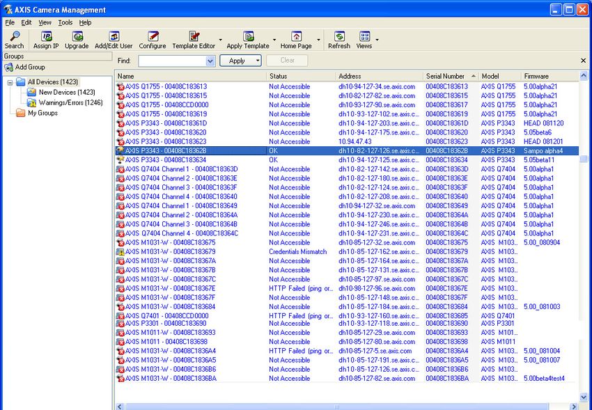
AXIS Camera Management - multiple cameras/large
installations
AXIS Camera Management can automatically discover multiple Axis devices, show connection
status, manage firmware upgrades, and set IP addresses.
Automatic discovery
1. Check that the camera is connected to the network and that power has been applied.
2. Start AXIS Camera Management. When the camera appears in the window, right-click the link
and select Live View Home Page.
3. See page 11 for instructions on how to set the password.
Assign an IP address in a single device
1. Select AXIS P3343-VE/P3344-VE in AXIS Camera Management
and click the Assign IP button .
2. Select Assign the following IP address and enter the IP
address, the subnet mask, and default router the device will
use.
3. Click OK.
Assign IP addresses in multiple devices
AXIS Camera Management speeds up the process of assigning IP
addresses to multiple devices, by suggesting IP addresses from a
specified range.
1. Select the devices you wish to configure (different models can be
selected) and click the Assign IP button .
2. Select Assign the following IP address range and enter the range
of IP addresses, the subnet mask, and default router the devices will use.
3. Click the OK button.AXIS P3343-VE/P3344-VE Installation Guide Page 11
Set the password
To gain access to the product, the password for the default administrator user root must be set. This
is done in the Configure Root Password dialog, which is displayed when the AXIS
P3343-VE/P3344-VE is accessed for the first time.
To prevent network eavesdropping when setting the root password, this can be done via an
encrypted HTTPS connection, which requires an HTTPS certificate.
To set the password via a standard HTTP connection, enter it in the Configure Root Password
window.
ENGLISH
To set the password via an encrypted HTTPS connection, follow these steps:
1. Click the Create self-signed certificate button.
2. Provide the requested information and click OK. The certificate is created and the password can
now be set securely. All traffic to and from the AXIS P3343-VE/P3344-VE Network Camera is
encrypted from this point on.
3. Enter a password and then re-enter it to confirm the spelling. Click OK. The password has now
been configured.
To create an HTTPS connection, start
by clicking this button.
To configure the password directly
via an unencrypted connection, enter
the password here.
4. To log in, enter the user name “root” in the dialog as requested.
Note: The default administrator user name root cannot be deleted.
5. Enter the password as set above, and click OK. If the password is lost, the AXIS
P3343-VE/P3344-VE must be reset to the factory default settings. See page 14.
If required, click Yes to install AMC (AXIS Media Control), which allows viewing of the video stream
in Internet Explorer. You will need administrator rights on the computer to do this.
The Live View page of the AXIS P3343-VE/P3344-VE appears. The Setup link to the right gives you
menu options that allow you to customize the camera.Page 12 AXIS P3343-VE/P3344-VE Installation Guide
Adjust the Lens
Open the Live View page in the web interface and
make the following adjustments to the camera: Horizon line
1. Loosen the locking screw and tilt adjustment
screws.
2. Turn the lens (with the lens holder) to the
desired position. Make sure the horizon lines
on either side of the lens are aligned
horizontally and the single slit between the
horizon lines is pointing down.
3. Once satisfied, gently tighten the locking
screw and tilt adjustment screws to secure the Tilt adjustment screw Tilt adjustment screw
camera’s position. Locking screw This part
must face down
4. Open the Focus Adjustment page in the Web
interface under Setup > Focus & Zoom, and follow the on-screen instructions. Use the image
window to adjust the focus and zoom.
Go to Setup > Video & Image > Advanced in your web interface and see the online help for
more information.
Note: Due to the dome’s refraction, the image may appear slightly out of focus once the dome has been
placed. To correct this go to the Focus Adjustment page in the Web interface under
Setup > Focus & Zoom, and adjust the focus again.
Warning! Adjusting the focus and zoom manually can damage the lens.
Complete the installation
1. Rotate the black protective shield inside the dome cover Black protective
shield
so it is aligned with the camera’s position.
2. If required, attach the weather shield to the camera before
you attach the dome cover. To do this remove the two
screws in the dome cover. Transfer the washers from these
screws to the two long screws provided. Attach the weather shield using the two long screws.
3. Attach the dome cover to the unit casing by tightening the 4 screws.AXIS P3343-VE/P3344-VE Installation Guide Page 13
Other methods of setting the IP address
The table below shows the other methods available for setting or discovering the IP address. All
methods are enabled by default, and all can be disabled.
Use in operating Notes
system
UPnP™ Windows When enabled on your computer, the camera is automatically
detected and added to “My Network Places.”
ENGLISH
Bonjour MAC OSX Applicable to browsers with support for Bonjour. Navigate to the
(10.4 or later) Bonjour bookmark in your browser (e.g. Safari) and click on the
link to access the camera’s web pages.
AXIS Dynamic DNS All A free service from Axis that allows you to quickly and simply
Service install your camera. Requires an Internet connection with no
HTTP proxy. See www.axiscam.net for more information.
ARP/Ping All See below. The command must be issued within 2 minutes of
connecting power to the camera.
View DHCP server All To view the admin pages for the network DHCP server, see the
admin pages server’s own documentation.
Set the IP address with ARP/Ping
1. Acquire a free static IP address on the same network segment your computer is connected to.
2. Locate the serial number (S/N) on the AXIS P3343-VE/P3344-VE label.
3. Open a command prompt on your computer and enter the following commands:
Windows syntax Windows example
arp -s arp -s 192.168.0.125 00-40-8c-18-10-00
ping -l 408 -t ping -l 408 -t 192.168.0.125
UNIX/Linux/Mac syntax UNIX/Linux/Mac example
arp -s temp arp -s 192.168.0.125 00:40:8c:18:10:00 temp
ping -s 408 ping -s 408 192.168.0.125
4. Restart the AXIS P3343-VE/P3344-VE, by disconnecting and reconnecting the network cable.
5. Close the command prompt when you see ‘Reply from 192.168.0.125:...’ or similar.
6. In your browser, type in http:// in the Location/Address field and press Enter on
your keyboard.
Notes:
• To open a command prompt in Windows: from the Start menu, select Run... and type cmd. Click OK.
• To use the ARP command on a Mac OS X, use the Terminal utility in Application > Utilities.Page 14 AXIS P3343-VE/P3344-VE Installation Guide
Unit connectors
Network connector - RJ-45 Ethernet connector. Supports Power over Ethernet. Using shielded
cables is recommended.
Audio in - 3.5mm input for a mono microphone, or a line-in mono signal (left channel is used from
a stereo signal).
Audio out - Audio output (line level) that can be connected to a public address (PA) system or an
active speaker with a built-in amplifier. A pair of headphones can also be attached. A stereo
connector must be used for the audio out.
SDHC memory card slot - The high capacity SD memory card can be used for local recording with
removable storage.
I/O terminal connector - Used in applications for e.g. motion detection,
event triggering, time lapse recording and alarm notifications. It provides the
interface to:
Pin4 Pin2
• 1 transistor output - For connecting external devices such as Pin3 Pin1
relays and LEDs. Connected devices can be activated by the
VAPIX Application Programming Interface (API), by the output buttons on the Live View
page or by an Event Type. The output will show as active (shown under Event Configu-
ration > Port Status) if the alarm device is activated.
• 1 digital input - An alarm input for connecting devices that can toggle between an
open and closed circuit, for example: PIRs, door/window contacts, and glass break
detectors. When a signal is received the state changes and the input becomes active
(shown under Event Configuration > Port Status).
• Auxiliary power and GND
Function Pin Notes Specifications
GND 1 Ground
3.3V DC 2 Can be used to power auxiliary equipment. Max. load = 50mA
Power Note: This pin can only be used as power out.
Digital 3 Connect to GND to activate, or leave floating (or Min. input= - 40V DC
Input unconnected) to deactivate. Max. input= + 40V DC
Digital 4 Uses an open-drain NFET transistor with the source Max. load = 100mA
Output connected to GND. If used with an external relay, a Max voltage = + 40V DC
diode must be connected in parallel with the load,
for protection against voltage transients.AXIS P3343-VE/P3344-VE Installation Guide Page 15
The following connection diagram gives an example of how to connect an auxiliary device to the
AXIS P3343-VE/P3344-VE.
1
E.g. push button
3.3V
max. 50mA 2
ENGLISH
3
D 4
G
S
LED indicators
LED Color Indication
Network Green Steady for connection to a 100 Mbit/s network. Flashes for network activity.
Amber Steady for connection to 10 Mbit/s network. Flashes for network activity.
Unlit No network connection.
Status Green Steady green for normal operation.
Amber Steady during startup; flashes once during reset to factory default or while
restoring settings.
Red Slow flash for failed upgrade.
Power Green Normal operation.
Amber Flashes green/amber during firmware upgrade.Page 16 AXIS P3343-VE/P3344-VE Installation Guide
Resetting to the Factory Default Settings
This will reset all parameters, including the IP address, to the Factory Default settings:
1. Disconnect power from the camera.
2. Press and hold the Control button (see Hardware Overview on page 4) and reconnect power.
3. Keep the Control button pressed until the Status indicator flashes amber (this may take up to15
seconds).
4. Release the Control button. When the Power indicator displays green (which can take up to 1
minute) the process is complete and the camera has been reset.
5. Re-assign the IP address, using one of the methods described in this document.
It is also possible to reset parameters to the original factory default settings via the web interface.
For more information, please see the online help or the user’s manual.
Accessing the camera from the Internet
Once installed, your AXIS P3343-VE/P3344-VE is accessible on your local network (LAN). To access
the camera from the Internet, network routers must be configured to allow incoming traffic, which
is usually done on a specific port
• HTTP port (default port 80) for viewing and configuration
• RTSP port (default port 554) for viewing H.264 video streams
Please refer to the documentation for your router for further instructions. For more information on
this and other topics, visit the Axis Support Web at www.axis.com/techsup
Further information
The user’s manual is available from the Axis Web site at www.axis.com or from the Axis Network
Video Product CD supplied with this product.
Tip!
Visit www.axis.com/techsup to check if there is updated firmware available for your AXIS product.
To see the currently installed firmware version, see Setup > About in your web interface.AXIS P3343-VE/P3344-VE Guide d’installation Page 17
Guide d’installation de la caméra AXIS P3343-VE/P3344-VE
Procédez comme suit pour installer la caméra réseau :
6. « Contenu de l’emballage » à la page 17
7. « Description du matériel » à la page 18
8. « Installation du matériel » à la page 19
9. « Attribution d’une adresse IP » à la page 22
10. « Configuration du mot de passe » à la page 25
11. « Réglage de l’objectif » à la page 27
12. « Fin de l’installation » à la page 27
Remarques :
FRANÇAIS
• Avant de commencer, vérifiez le contenu de l’emballage et assurez-vous que l’alimentation ainsi que les
câbles, les outils et la documentation nécessaires sont disponibles. Reportez-vous à la section Contenu de
l’emballage ci-dessous.
• Cette caméra réseau est conçue pour fonctionner avec un connecteur réseau (PoE). Si vous n’en disposez
pas, utilisez Axis PoE Midspan à 1 port (non inclus)
Contenu de l’emballage
Élément Modèles/variantes/remarques
Caméra réseau avec module AXIS P3343-VE/ AXIS P3344-VE
chauffant
Support de fixation
Bulles du dôme Couvercle transparent non fumé
Couvercle transparent fumé
Blindage de câble
Protection étanche
Étiquettes 2 étiquettes adhésives portant le numéro de série
Kit de montage Tournevis Resitorx, gabarit de perçage, câble réseau de 5 mètres avec joint
4 vis et chevilles, 2 longues vis, 2 vis M4x8
1 joint, bloc de connexion pour terminaux
CD CD du produit de vidéo sur IP AXIS comprenant la documentation,
les outils d’installation et les autres logiciels
Documentation imprimée Guide d’installation (le présent document)
Document de garantie d’Axis
Accessoires en option Consultez le site à l’adresse www.axis.com pour plus d’informations sur les
accessoires disponibles
.Page 18 AXIS P3343-VE/P3344-VE Guide d'installation
Description du matériel
Caméra
Radiateur
Connecteur E/S
Connecteur réseau Bouton de commande
(PoE) Témoins DEL
Entrée audio Sortie audio
Support de fixation
Boîtier de l’unité
Ressort
Logement de carte mémoire SD
Bulle du dôme
Caméra
Protection étanche
Trous pour les câbles
acheminés dans le mur Numéro de série
Trous latéraux avec
joints pour les câbles
acheminés le long du mur
Attention !
Le radiateur de la caméra peut être chaud.AXIS P3343-VE/P3344-VE Guide d’installation Page 19
Installation du matériel
Préparation du câble réseau
Si vous utilisez un câble autre que celui fourni, il est alors nécessaire de préparer un câble réseau
avec un joint. Faites passer délicatement le câble à travers le joint fourni et branchez un connecteur
réseau. Il peut être nécessaire de percer un trou dans le joint à l’aide du tournevis resitorx.
FRANÇAIS
Remarque :
• Ne forcez pas le connecteur réseau dans le joint.
• Ne percez pas le joint avec un couteau ou avec un autre objet pointu.
Préparation du boîtier de l’unité (acheminement des câbles le long du mur)
Si les câbles doivent être acheminés le long du mur, préparez le boîtier de l’unité de la manière
suivante :
1. Détachez le couvercle latéral du boîtier de l’unité en retirant la vis.
2. Dévissez les deux vis sur le blindage de câble et détachez la partie inférieure.
3. Fixez la partie inférieure du blindage de câble au boîtier de l’unité avec la vis.
Boîtier de l’unité Blindage de câble Boîtier de l’unité
Vis
Couvercle latéral
Partie supérieure
Partie inférieure
Remplacement du couvercle de dôme fumé ou non fumé (facultatif)
La caméra AXIS P3343-VE/P3344-VE est livrée avec un dôme facultatif. Pour remplacer le couvercle
de dôme :
1. Dévissez les 4 vis sous le couvercle de dôme qui maintiennent le dôme en place.
2. Transférez le joint de l’ancien dôme au nouveau dôme.
3. Remplacez l’ancien dôme par le nouveau et serrez les vis.Page 20 AXIS P3343-VE/P3344-VE Guide d'installation
Acheminement des câbles
Suivez les instructions appropriées indiquées ci-dessous, selon un acheminement des câbles le long
du mur ou dans le mur.
Acheminement des câbles le long du mur
1. En vous servant du gabarit de perçage, percez 4 trous dans le mur.
2. Fixez le support de fixation au mur à l’aide des 4 vis fournies ou utilisez des vis adaptées au
matériau du mur.
3. Retirez la caméra du boîtier de l’unité en écartant les ressorts.
4. Retirez les joints des trous latéraux du boîtier de l’unité. S’il n’y a qu’un seul câble, retirez un
seul joint.
5. Posez le boîtier de l’unité sur le support de fixation et fixez-le en serrant les quatre vis.
6. Faites passer les câbles à travers les trous latéraux du boîtier de l’unité.
7. Faites glisser les joints le long du câble et fixez-les dans les trous. Les joints doivent être ajustés
parfaitement aux trous sans plis ni courbures.
8. Fixez à nouveau la partie supérieure du blindage de câble en resserrant les deux vis.
Remarque : Pour éviter des problèmes liés à l’humidité, il est recommandé d’acheminer les câbles vers la
caméra par en dessous, les trous des câbles étant dirigés vers le bas.
Acheminement des câbles dans le mur
1. En vous servant du gabarit de perçage, percez 4 trous dans le mur.
2. Acheminez le câble réseau (ainsi que le câble d’E/S et le câble audio si nécessaire) dans le mur
et dans les trous du support de fixation.
3. Fixez le support de fixation au mur à l’aide des 4 vis fournies ou utilisez des vis adaptées au
matériau du mur.
4. Retirez la caméra du boîtier de l’unité en écartant les ressorts.
5. Retirez les joints des trous arrière du boîtier de l’unité. S’il n’y a qu’un seul câble, retirez un seul
joint.
6. Acheminez les câbles par ces trous.
7. Faites glisser les joints le long des câbles et fixez-les dans les trous. Les joints doivent être
ajustés parfaitement aux trous sans plis ni courbures.
8. Fixez le boîtier de l’unité au
support de fixation en serrant les
quatre vis.
Retirez les joints
des trous
Support de fixation
Boîtier de l’unité
Câble réseau avec jointAXIS P3343-VE/P3344-VE Guide d’installation Page 21
Installation de la caméra
Connecteur pour ventilateur
Caméra
Vis
fixée à la caméra
Câble réseau
FRANÇAIS
1. Fixez le câble réseau à la caméra ainsi que le câble audio et le câble d’E/S si nécessaire. Il est
recommandé d’enrouler le câble réseau pour former une boucle comme indiqué dans la figure
ci-dessus.
Remarque : Veillez à ne pas trop étirer ou tordre le câble réseau. Cela pourrait l’endommager.
2. Insérez la carte mémoire SD (facultatif).
3. Écartez les ressorts du boîtier de l’unité et mettez en place la caméra (vous devez entendre un
clic lorsque la caméra est correctement enclenchée).
4. Fixez le connecteur de ventilateur au connecteur de la caméra.
5. Fixez les deux vis M4x8 20 à la caméra pour une meilleure stabilité.
Ces vis sont uniquement nécessaires pour protéger l’unité contre les vibrations et les chocs
importants.
Remarque : La caméra AXIS P3343-VE/P3344-VE peut également
être dotée d’un conduit métallique pour protéger le
câblage lors d’un acheminement des câbles le long du mur.
ConduitPage 22 AXIS P3343-VE/P3344-VE Guide d'installation
Attribution d’une adresse IP
La caméra réseau AXIS P3343-VE/AXIS P3344-VE est conçue pour une utilisation sur un réseau
Ethernet et nécessite une adresse IP pour y accéder. Aujourd’hui, la plupart des réseaux sont
équipés d’un serveur DHCP qui attribue automatiquement des adresses IP aux périphériques
connectés. Si votre réseau ne possède pas de serveur DHCP, la caméra réseau AXIS P3343-VE/AXIS
P3344-VE utilise l’adresse IP 192.168.0.90 comme adresse IP par défaut.
Si vous souhaitez définir une adresse IP statique sous Windows, nous recommandons l’utilisation de
l’application AXIS IP Utility ou d’AXIS Camera Management. Ces deux applications gratuites sont
disponibles sur le CD accompagnant votre caméra réseau Axis. Vous pouvez également les
télécharger à partir du site www.axis.com/techsup. Choisissez la méthode qui vous convient le
mieux en fonction du nombre de caméras à installer.
Méthode Recommandée pour Système
d’exploitation
AXIS IP Utility Une seule caméra Windows
Voir page 23 Petites installations
AXIS Camera Management Plusieurs caméras Windows 2000
Voir page 24 Grandes installations Windows XP Pro
Installation sur un autre Windows 2003 Server
sous-réseau Windows Vista
Remarque : Si vous n’arrivez pas à configurer l’adresse IP, vérifiez qu’aucun pare-feu ne bloque
l’opération.
Pour connaître les autres méthodes de configuration ou de détection de l’adresse IP de la caméra
réseau AXIS P3343-VE/AXIS P3344-VE sous d’autres systèmes d’exploitation, reportez-vous à la
page 28.AXIS P3343-VE/P3344-VE Guide d’installation Page 23
AXIS IP Utility : une seule caméra et une petite installation
AXIS IP Utility recherche et affiche automatiquement les périphériques Axis présents sur votre
réseau. Cette application permet également de définir manuellement une adresse IP statique. Vous
trouverez l’application AXIS IP Utility sur le CD accompagnant votre caméra réseau Axis. Vous
pouvez également la télécharger à partir du site www.axis.com/techsup.
FRANÇAIS
Notez que vous devez installer la caméra réseau AXIS P3343-VE/P3344-VE sur le même segment de
réseau (sous-réseau physique) que l’ordinateur exécutant l’application AXIS IP Utility.
Détection automatique
1. Vérifiez que la caméra réseau AXIS P3343-VE/P3344-VE est connectée au réseau et que
l’alimentation est activée.
2. Lancez AXIS IP Utility.
3. Double-cliquez sur la caméra AXIS P3343-VE/P3344-VE lorsque celle-ci apparaît dans la
fenêtre. Vous accéderez ainsi à la page d’accueil de la caméra.
4. Reportez-vous à la page 25 pour savoir comment configurer le mot de passe.
Configuration manuelle de l’adresse IP (facultatif)
1. Trouvez une adresse IP non utilisée sur le même segment de réseau que celui de votre
ordinateur.
2. Sélectionnez AXIS P3343-VE/P3344-VE dans la liste.
3. Cliquez sur le bouton Assign new IP address to selected device (Attribuer une nouvelle
adresse IP au périphérique sélectionné) et saisissez l’adresse IP.
4. Cliquez sur le bouton Assign (Attribuer) et suivez les instructions à l’écran. La caméra doit être
redémarrée dans les deux minutes pour que la nouvelle adresse IP soit prise en compte.
5. Cliquez sur le bouton Home Page (Page d’accueil) pour accéder aux pages Web de la caméra.
6. Reportez-vous à la page 25 pour savoir comment configurer le mot de passe.Page 24 AXIS P3343-VE/P3344-VE Guide d'installation
AXIS Camera Management : plusieurs caméras et de grandes
installations
AXIS Camera Management peut détecter automatiquement plusieurs périphériques Axis, afficher
l’état de connexion, gérer les mises à niveau du micrologiciel et configurer les adresses IP.
Détection automatique
1. Vérifiez que la caméra est connectée au réseau et sous tension.
2. Lancez AXIS Camera Management. Lorsque la caméra apparaît dans la fenêtre, cliquez sur le
lien avec le bouton droit de la souris et sélectionnez Live View Home Page (Page d’accueil –
Vidéo en direct).
3. Reportez-vous à la page 25 pour savoir comment configurer le mot de passe.
Attribution d’une adresse IP à un seul périphérique
1. Sélectionnez AXIS P3343-VE/P3344-VE dans l’application AXIS
Camera Management, puis cliquez sur le bouton Assign IP
(Attribuer une adresse IP) .
2. Sélectionnez Assign the following IP address (Attribuer
l’adresse IP suivante) et saisissez l’adresse IP, le masque de
sous-réseau et le routeur par défaut que le périphérique utilisera.
3. Cliquez sur OK.AXIS P3343-VE/P3344-VE Guide d’installation Page 25
Attribution d’adresses IP à plusieurs périphériques
AXIS Camera Management accélère le processus d’attribution
d’adresses IP à plusieurs périphériques en suggérant des adresses IP
dans une plage spécifiée.
1. Sélectionnez les périphériques à configurer (il peut s’agir de
modèles différents), puis cliquez sur le bouton Assign IP (Attribuer
adresses IP) .
2. Sélectionnez Assign the following IP address range (Attribuer la
plage d’adresses IP suivante) et saisissez la plage d’adresses IP, le masque de sous-réseau et le
routeur par défaut que les périphériques utiliseront.
3. Cliquez sur le bouton OK.
Configuration du mot de passe
FRANÇAIS
Pour accéder au produit, le mot de passe par défaut de l’administrateur, root, doit être configuré.
Pour ce faire, utilisez la boîte de dialogue Configure Root Password (Configurer le mot de passe
root) qui s’affiche lorsque vous accédez à la caméra AXIS P3343-VE/P3344-VE pour la première fois.
Pour éviter les écoutes électroniques lors de la configuration du mot de passe root, utilisez une
connexion HTTPS cryptée nécessitant un certificat HTTPS.
Pour configurer le mot passe avec une connexion HTTP standard, saisissez-le dans la fenêtre
Configure Root Password (Configurer le mot de passe root).
Pour configurer le mot passe avec une connexion HTTPS cryptée, procédez comme suit :
1. Cliquez sur le bouton Create self-signed certificate (Créer un certificat autosigné).
2. Saisissez les informations demandées, puis cliquez sur OK. Le certificat est créé et le mot de
passe peut maintenant être configuré en toute sécurité. Tout le trafic vers et depuis la caméra
réseau AXIS P3343-VE/P3344-VE est désormais crypté.Page 26 AXIS P3343-VE/P3344-VE Guide d'installation
3. Saisissez un mot de passe, puis saisissez-le de nouveau pour confirmation. Cliquez sur OK. Le
mot de passe est maintenant configuré.
Pour créer une connexion HTTPS,
cliquez sur ce bouton.
Pour configurer directement le mot
de passe via une connexion cryptée,
saisissez le mot de passe à cet
4. Pour vous connecter, saisissez le nom d’utilisateur « root » dans la boîte de dialogue à l’invite.
Remarque : Le nom d’utilisateur par défaut de l’administrateur est root et il ne peut pas être supprimé.
5. Saisissez le mot de passe de la manière indiquée ci-dessus et cliquez sur OK. Si vous avez oublié
votre mot de passe, vous devrez rétablir les paramètres d’usine par défaut de la caméra AXIS
P3343-VE/P3344-VE. Reportez-vous à la page 29.
Si le système vous le demande, cliquez sur Yes (Oui) pour installer AMC (AXIS Media Control) afin de
pouvoir visualiser les flux de données vidéo dans Internet Explorer. Pour ce faire, vous devrez être
connecté à l’ordinateur avec des droits d’administrateur.
La page Live View (Vue en direct) de la caméra AXIS P3343-VE/P3344-VE s’affiche. Le lien Setup
(Configuration) à droite contient toutes les options de menu nécessaires pour adapter la caméra à
vos besoins.AXIS P3343-VE/P3344-VE Guide d’installation Page 27
Réglage de l’objectif
Ouvrez la page Live View (Vue en direct) dans
l’interface Web et effectuez les réglages suivants Ligne d’horizon
sur la caméra :
1. Desserrez la vis de verrouillage et les vis de
réglage de l’inclinaison.
2. Tournez l’objectif (à l’aide du porte-objectif)
dans la position souhaitée. Assurez-vous que
les lignes d’horizon de chaque côté de
l’objectif sont alignées horizontalement et que
la fente unique située entre les lignes
Vis de réglage de
d’horizon pointe vers le bas. Vis de réglage de l’inclinaison
l’inclinaison
3. Une fois que vous avez terminé, serrez Vis de verrouillage Cette partie
doit être dirigée vers le bas
délicatement la vis de verrouillage et les vis de
FRANÇAIS
réglage de l’inclinaison pour bien fixer la
caméra.
4. Ouvrez la page Focus Adjustment (Réglage de la mise au point) de l’interface Web sous Setup
> Focus & Zoom (Configuration - Mise au point et zoom) et suivez les instructions à l’écran.
Utilisez la fenêtre d’image pour régler le zoom et la mise au point.
Cliquez sur Setup > Video & Image > Advanced (Configuration - Vidéo et image - Avancé)
dans l’interface Web de la caméra et consultez l’aide en ligne pour plus d’informations.
Remarque : Du fait de la réfraction du dôme, l’image peut apparaître légèrement floue une fois le dôme
installé. Pour corriger l’image, ouvrez la page Focus Adjustment (Réglage de la mise au point) de
l’interface Web sous Setup > Focus & Zoom (Configuration - Mise au point et zoom) et réglez à
nouveau la mise au point.
Avertissement : Régler la mise au point et le zoom manuellement peut endommager l’objectif.
Fin de l’installation
1. Tournez l’écran protecteur noir à l’intérieur du couvercle Écran protecteur
noir
de dôme afin de l’aligner avec la position de la caméra.
2. Si nécessaire, fixez la protection étanche sur la caméra
avant de fixer le couvercle de dôme. Pour cela, retirez les
deux vis du couvercle de dôme. Transférez les rondelles de
ces vis sur les deux longues vis fournies. Fixez la protection étanche en utilisant les deux
longues vis.
3. Fixez le couvercle de dôme sur le boîtier de l’unité en serrant les 4 vis.Page 28 AXIS P3343-VE/P3344-VE Guide d'installation
Autres méthodes de définition de l’adresse IP
Le tableau ci-dessous indique les autres méthodes permettant de configurer ou de déterminer
l’adresse IP. Toutes les méthodes sont activées par défaut et peuvent être désactivées.
Utilisation sous le Remarques
système
d’exploitation
UPnP™ Windows Lorsque la caméra est activée sur votre ordinateur, elle est
détectée et ajoutée automatiquement au dossier Favoris réseau.
Bonjour MAC OSX Pour les navigateurs compatibles avec Bonjour. Accédez au
(10.4 ou version signet de Bonjour dans votre navigateur (par exemple, Safari),
ultérieure) puis cliquez sur le lien pour accéder aux pages Web de la caméra.
AXIS Dynamic DNS Tous Service Axis gratuit permettant d’installer rapidement et
Service facilement votre caméra. Nécessite une connexion Internet sans
proxy HTTP. Pour plus d’informations, rendez-vous sur
www.axiscam.net.
ARP/Ping Tous Reportez-vous aux instructions ci-dessous. La commande doit
être saisie dans les 2 minutes suivant la mise sous tension de la
caméra.
Affichage des Tous Pour consulter les pages administratives du serveur DHCP réseau,
pages reportez-vous à la documentation du serveur.
administratives du
serveur DHCP
Définition de l’adresse IP à l’aide d’ARP/Ping
1. Trouvez une adresse IP statique disponible sur le même segment de réseau que celui de votre
ordinateur.
2. Repérez le numéro de série (S/N) sur l’étiquette de la caméra AXIS P3343-VE/P3344-VE.
3. Ouvrez une invite de commande sur votre ordinateur et saisissez les commandes suivantes :
Syntaxe pour Windows Exemple pour Windows
arp -s arp -s 192.168.0.125 00-40-8c-18-10-00
ping -l 408 -t ping -l 408 -t 192.168.0.125
Syntaxe pour UNIX/Linux/Mac Exemple pour UNIX/Linux/Mac
arp -s temp arp -s 192.168.0.125 00:40:8c:18:10:00 temp
ping -s 408 ping -s 408 192.168.0.125
4. Redémarrez la caméra AXIS P3343-VE/P3344-VE en débranchant et en rebranchant le câble
réseau.
5. Fermez l’invite de commande lorsque « Reply from 192.168.0.125:... » (Réponse de
192.168.0.125: ...) ou un message similaire apparaît.AXIS P3343-VE/P3344-VE Guide d’installation Page 29
6. Dans votre navigateur, saisissez http:// dans le champ Emplacement/Adresse, puis
appuyez sur la touche Entrée de votre clavier.
Remarques :
• Ouvrir une invite de commande sous Windows : dans le menu Démarrer, sélectionnez Exécuter… et tapez
cmd. Cliquez sur OK.
• Pour utiliser la commande ARP sous Mac OS X, utilisez l’utilitaire Terminal dans Application > Utilitaires.
Connecteurs de l’appareil
Connecteur réseau : connecteur Ethernet RJ-45. Prend en charge l’alimentation par Ethernet. Il est
recommandé d’utiliser des câbles blindés.
Entrée audio : entrée de 3,5 mm pour microphone mono ou signal mono avec entrée de haut
niveau (le canal de gauche est utilisé pour le signal stéréo).
FRANÇAIS
Sortie audio : sortie audio (niveau de ligne) qui peut être connectée à un système d’annonce
publique (PA) ou haut-parleur actif avec amplificateur intégré. Il est également possible de
connecter une paire d’écouteurs. Un connecteur stéréo doit être utilisé pour la sortie audio.
Logement de carte mémoire SDHC : la carte mémoire SD haute capacité peut être utilisée pour
l’enregistrement local avec stockage amovible.
Connecteur pour terminaux E/S : utilisé dans le cadre d’applications telles
que la détection de mouvement, le déclenchement d’événements,
l’enregistrement à intervalles et les notifications d’alarme. Il assure
l’interface avec : Broche 4 Broche 2
Broche 3 Broche 1
• 1 sortie transistor, qui permet de connecter des périphériques
externes, comme des relais ou des DEL. Les périphériques connectés peuvent être
activés à l’aide de l’interface de programmation (API) VAPIX, des boutons de sortie sur
la page Live View (Vue en direct) ou à l’aide d’un type d’événement. La sortie est
considérée comme active (dans Event Configuration > Port Status [Configuration
d’événement - État du port]) si le dispositif d’alarme est activé.
• 1 entrée numérique : une entrée d’alarme utilisée pour connecter des périphériques
pouvant passer d’un circuit ouvert à un circuit fermé, avec par exemple des détecteurs
infrarouges passifs, des contacts de porte/fenêtre et des détecteurs de bris de verre.
Lorsqu’un signal est reçu, l’état change et l’entrée devient active (sous Event
Configuration > Port Status [Configuration d’événement - État du port]).Page 30 AXIS P3343-VE/P3344-VE Guide d'installation
• Alimentation auxiliaire et mise à la terre
Fonction Broc Remarques Caractéristiques
he techniques
GND 1 Mise à la terre
Alimentation 2 Peut servir à alimenter le matériel auxiliaire. Charge maximale =
en courant Remarque : la broche peut être utilisée uniquement 50 mA
continu de comme sortie d’alimentation.
3,3 V
Entrée 3 Peut être connectée à GND pour l’activer ou laisser Entrée minimum = 40 V
numérique pendre (ou déconnectée) si on préfère ne pas CC
l’activer. Entrée maximum = 40 V
CC
Sortie 4 Utilise un transistor NFET à drain ouvert avec la Charge maximale =
numérique source connectée à la terre. En cas d’utilisation avec 100 mA
un relais externe, une diode doit être connectée en Tension maximale = +
parallèle avec la charge, en guise de protection 40 V CA
contre les tensions transitoires.
Le schéma de câblage suivant est un exemple de connexion d’un périphérique auxiliaire à la caméra
AXIS P3343-VE/P3344-VE.
1
E.g. push button
3.3V
max. 50mA 2
3
D 4
G
SAXIS P3343-VE/P3344-VE Guide d’installation Page 31
Témoins DEL
DEL Couleur Indication
Réseau Vert Continu en cas de connexion à un réseau de 100 Mbits/s. Clignote en cas
d’activité réseau.
Orange Continu en cas de connexion à un réseau de 10 Mbits/s. Clignote en cas
d’activité réseau.
Éteint Pas de connexion au réseau.
État Vert Vert continu en cas de fonctionnement normal.
Orange En continu pendant le démarrage, clignote une fois pendant la réinitialisation
des valeurs d’usine par défaut ou la restauration des paramètres.
Rouge Clignote lentement en cas d’échec de la mise à niveau.
Alimentation Vert Fonctionnement normal.
FRANÇAIS
Orange Clignote en vert/orange pendant la mise à niveau des microprogrammes.Page 32 AXIS P3343-VE/P3344-VE Guide d'installation
Rétablissement des paramètres d’usine par défaut
Procédez comme suit pour rétablir tous les paramètres par défaut définis en usine, y compris
l’adresse IP :
1. Débranchez l’alimentation de la caméra.
2. Maintenez le bouton de commande enfoncé (reportez-vous à la présentation du matériel à la à
la page 18) et rebranchez l’alimentation.
3. Appuyez sur le bouton de commande jusqu’à ce que l’indicateur d’état clignote en orange (cela
peut prendre jusqu’à 15 secondes).
4. Relâchez le bouton de commande. Une lumière verte émise par le voyant d’alimentation (peut
prendre 1 minute) indique que l’opération est terminée et que la caméra a été réinitialisée.
5. Attribuez à nouveau l’adresse IP selon une des méthodes décrites dans ce document.
Il est également possible de rétablir les paramètres d’usine par défaut d’origine à partir de
l’interface Web. Pour plus d’informations, reportez-vous à l’aide en ligne ou au manuel d’utilisation.
Accès à la caméra sur Internet
Une fois installée, la caméra AXIS P3343-VE/P3344-VE est accessible sur votre réseau local (LAN).
Pour accéder à la caméra sur Internet, les routeurs réseau doivent être configurés pour autoriser le
trafic entrant, ce qui est généralement réalisé sur un port spécifique :
• Le port HTTP (port 80 par défaut) pour l’affichage et la configuration
• Le port RTSP (port 554 par défaut) pour l’affichage des flux de données vidéo H.264
Pour plus d’informations, consultez la documentation du routeur. Pour plus d’informations à ce
sujet ou pour toute autre question, consultez la page d’assistance technique d’Axis à l’adresse
www.axis.com/techsup.
Plus d’informations
Le manuel de l’utilisateur est disponible sur le site Web d’Axis (www.axis.com) et sur le CD fourni
avec ce produit.
Conseil :
Visitez le site www.axis.com/techsup pour vérifier si des micrologiciels mis à jour sont disponibles
pour votre produit AXIS. Pour connaître la version du micrologiciel actuellement installée,
reportez-vous à la page Setup > About (Configuration - À propos de) dans votre interface Web.Vous pouvez aussi lire