INSTALLATION GUIDE AXIS Q60 Series AXIS Q6032-E PTZ Dome Network Camera AXIS Q6034-E PTZ Dome Network Camera AXIS Q6035-E PTZ Dome Network Camera
←
→
Transcription du contenu de la page
Si votre navigateur ne rend pas la page correctement, lisez s'il vous plaît le contenu de la page ci-dessous
INSTALLATION GUIDE

AXIS Q60 Series

                                           ENGLISH
    AXIS Q6032-E PTZ Dome Network Camera
    AXIS Q6034-E PTZ Dome Network Camera

                                           FRANÇAIS
    AXIS Q6035-E PTZ Dome Network Camera

                                           DEUTSCH
                                           ITALIANO
                                           ESPAÑOL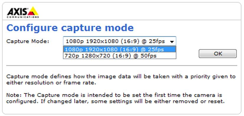
Legal Considerations Korea - AXIS Q6035-E: ࢇ̛̛Е߶ ࡈה$̗
Video and audio surveillance can be prohibited by laws ࢷળࢶଢ̛̛Ի۰શӖЕࡈیЕࢇࢺࡶ
that vary from country to country. Check the laws in your ࣯ࢂଜ̛ݤԂֲɼࢽ࠹ࢂएࠇ߾۰ࡈیଜЕʨࡶ
local region before using this product for surveillance ּࢶࡳԻଢТЬ
purposes. This product includes one (1) H.264 decoder
license. To purchase further licenses, contact your reseller. Safety
Trademark Acknowledgments Complies to EN 60950-1 (IEC 60950-1), Safety of
Apple, Boa, Bonjour, Ethernet, Internet Explorer, Linux, Information Technology Equipment.
Microsoft, Mozilla, Netscape Navigator, OS/2, Real, SMPTE, Equipment Modifications
QuickTime, UNIX, Windows, WWW are registered This equipment must be installed and used in strict
trademarks of the respective holders. Java and all accordance with the instructions given in the user
Java-based trademarks and logos are trademarks or documentation. This equipment contains no
registered trademarks of Sun Microsystems, Inc. in the user-serviceable components. Unauthorized equipment
United States and other countries. Axis Communications changes or modifications will invalidate all applicable
AB is independent of Sun Microsystems Inc. UPnP™ is a regulatory certifications and approvals.
certification mark of the UPnP™ Implementers
Corporation. Liability
Electromagnetic Compatibility (EMC) Every care has been taken in the preparation of this
document. Please inform your local Axis office of any
This equipment generates, uses and can radiate radio inaccuracies or omissions. Axis Communications AB
frequency energy and, if not installed and used in cannot be held responsible for any technical or
accordance with the instructions, may cause harmful typographical errors and reserves the right to make
interference to radio communications. However, there is changes to the product and documentation without prior
no guarantee that interference will not occur in a notice. Axis Communications AB makes no warranty of any
particular installation. kind with regard to the material contained within this
If this equipment does cause harmful interference to radio document, including, but not limited to, the implied
or television reception, which can be determined by warranties of merchantability and fitness for a particular
turning the equipment off and on, the user is encouraged purpose. Axis Communications AB shall not be liable nor
to try to correct the interference by one or more of the responsible for incidental or consequential damages in
following measures: Re-orient or relocate the receiving connection with the furnishing, performance or use of this
antenna. Increase the separation between the equipment material. This product is only to be used for its intended
and receiver. Connect the equipment to an outlet on a purpose.
different circuit to the receiver. Consult your dealer or an
experienced radio/TV technician for help. Shielded (STP) RoHS
network cables must be used with this unit to ensure This product complies with both the European
compliance with EMC standards. RoHS directive, 2002/95/EC, and the Chinese
USA - This equipment has been tested and found to RoHS regulations, ACPEIP.
comply with the limits for a Class B computing device WEEE Directive
pursuant to Subpart B of Part 15 of FCC rules, which are The European Union has enacted a Directive
designed to provide reasonable protection against such 2002/96/EC on Waste Electrical and Electronic
interference when operated in a commercial environment. Equipment (WEEE Directive). This directive is
Operation of this equipment in a residential area is likely applicable in the European Union member
to cause interference, in which case the user at his/her states. The WEEE marking on this product (see
own expense will be required to take whatever measures right) or its documentation indicates that the product
may be required to correct the interference. must not be disposed of together with household waste.
Canada - This Class B digital apparatus complies with To prevent possible harm to human health and/or the
Canadian ICES-003. environment, the product must be disposed of in an
approved and environmentally safe recycling process. For
Europe - This digital equipment fulfills the further information on how to dispose of this product
requirements for RF emission according to limit B of correctly, contact the product supplier, or the local
EN 55022. This product fulfills the requirements for authority responsible for waste disposal in your area.
immunity according to EN 61000-6-2 industrial Business users should contact the product supplier for
enviroments and EN 55024. information on how to dispose of this product correctly.
Japan - This is a class B product based on the standard This product should not be mixed with other commercial
of the Voluntary Control Council for Interference from waste.
Information Technology Equipment (VCCI). If this is used
near a radio or television receiver in a domestic Support
environment, it may cause radio interference. Install and Should you require any technical assistance, please
use the equipment according to the instruction manual. contact your Axis reseller. If your questions cannot be
answered immediately, your reseller will forward your
Australia - This electronic device meets the queries through the appropriate channels to ensure a rapid
requirements of the Radio communications response. If you are connected to the Internet, you can:
(Electromagnetic Compatibility) Standard AS/NZS • download user documentation and firmware updates
CISPR22:2002. • find answers to resolved problems in the FAQ database.
Korea - AXIS Q6032-E/Q6034-E: ࢇ̛̛Еɼࢽࡈ % Search by product, category, or phrases
̗ ࢷળࢶଢ̛̛Ի۰࣯Իɼࢽ߾۰ࡈیଜЕ • report problems to Axis support by logging in to your
ʨࡶּࢶࡳԻଜֲֻҘएࠇ߾۰ࡈیଟܹ private support area
ݡТЬ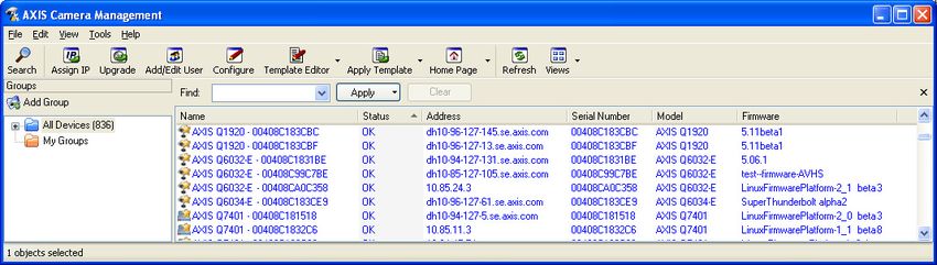
Safeguards
Please read through this Installation Guide carefully before installing the product. Keep the Installation Guide
for further reference.

     CAUTION!
•   When transporting the Axis product, use the original packaging or equivalent to prevent damage to the
    product.
•   Store the Axis product in a dry and ventilated environment.
•   Avoid exposing the Axis product to vibration, shocks or heavy pressure and do not install the camera on
    unstable brackets, unstable or vibrating surfaces or walls, since this could cause damage to the product.
•   Only use handtools when installing the Axis product, the use of electrical tools or excessive force could
    cause damage to the product.
•   Do not use chemicals, caustic agents, or aerosol cleaners. Use a damp cloth for cleaning.

                                                                                                                   ENGLISH
•   Use only accessories that comply with technical specification of the product. These can be provided by Axis
    or a third party.
•   Use only spare parts provided by or recommended by Axis.
•   Do not attempt to repair the product by yourself, contact Axis or your Axis reseller for service matters.

     IMPORTANT!
•   This Axis product must be used in compliance with local laws and regulations.

Battery replacement
This Axis product uses a 3.0V CR2032 Lithium battery as the power supply for its internal real-time clock (RTC).
Under normal conditions this battery will last for a minimum of 5 years. Low battery power affects the
operation of the RTC, causing it to reset at every power-up. A log message will appear when the battery needs
replacing. The battery should not be replaced unless required!
If the battery does need replacing, please contact www.axis.com/techsup for assistance.
•   Danger of Explosion if battery is incorrectly replaced.
•   Replace only with the same or equivalent battery, as recommended by the manufacturer.
•   Dispose of used batteries according to the manufacturer's instructions.

Cleaning of dome cover
•   Be careful not to scratch or damage the dome cover. Do not clean a dome cover that looks clean to the eye
    and never polish the surface. Excessive cleaning can damage the surface.
•   For general cleaning of a dome cover it is recommended to use a non-abrasive, solvent-free neutral soap or
    detergent with water and a soft cloth. Rinse well with clean lukewarm water. Dry with a soft cloth to pre-
    vent water spotting.
•   Never use harsh detergents, gasoline, benzene or acetone etc. and avoid cleaning in direct sunlight or at
    elevated temperatures.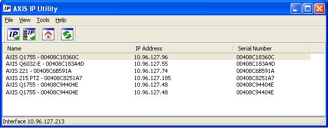
AXIS Q6032-E/Q6034-E/Q6035-E Installation Guide                                                Page 5

         AXIS Q6032-E/Q6034-E/Q6035-E
                Installation Guide
This installation guide provides instructions for installing an AXIS Q6032-E/Q6034-E/Q6035-E PTZ
Dome Network Camera on your network. For all other aspects of using the product, please see the
User Manual, available on the CD included in this package, or from www.axis.com

Installation steps

                                                                                                        ENGLISH
1.   Check the package contents against the list below.
2.   Hardware overview. See page 6.
3.   Install the hardware. See page 7.
4.   Assign an IP address. See page 11.
5.   Set the password. See page 14.

     Package contents
Item                         Models/variants/notes

Network camera               AXIS Q6032-E/Q6034-E/Q6035-E
Dome covers                  Clear transparent cover (pre-mounted)
High PoE Midspan             AXIS T8124 including power cable (country specific)
RJ45 connector               IP66-rated network connector
Sunshield                    Plastic protective cover, including screws
CD                           AXIS Network Video Product CD, including product documentation,
                             installation tools and other software
Printed materials            AXIS Q6032-E/Q6034-E/Q6035-E Installation Guide (this document)
                             Axis Warranty Document
                             Extra serial number labels (2x)
                             AVHS Authentication key

Optional accessories         AXIS T91A Mounting Accessories
                             See www.axis.com for information on available accessories
Page 6 AXIS Q6032-E/Q6034-E/Q6035-E Installation Guide
Hardware overview
Screw holes
Sunshield
Holes for unit holders
Power button
Camera unit (for Factory
Heater Default only)
Caution!
may be hot
Hook for safety wire
Unit holders (3) Network connector
(PoE)
SD memory card slot Control button
Status indicator LED
Part number (P/N) & Serial number (S/N).
The serial number may be required
during the installation.
Metal ring Metal Rubber Dome ring Dome ring Dome cover
screws (4) ring gasket screws (4)
Dome coverAXIS Q6032-E/Q6034-E/Q6035-E Installation Guide Page 7
Install the hardware
Prepare for installation
Read all the instructions before preparing to install the network camera since several installation
preparation steps require removing the dome ring and the dome cover and would benefit from
being completed together.
• The network camera is supplied with an optional sunshield. If required, follow the instruc-
tions Attach the sunshield (optional), below to attach the sunshield.
• The network camera is supplied with a clear transparent cover. If required, follow the
ENGLISH
instructions Replace the clear/smoked dome cover (optional), below to replace the dome
cover.
• A standard or high capacity SD card (not included) is required to store images locally in the
network camera. Follow the instructions Install an SD card (optional), below to remove the
dome cover and install an SD card.
Attach the sunshield (optional)
1. Slide the sunshield over the unit holders on the dome camera unit.
2. Secure the sunshield using the supplied screws (Torx T20).
Replace the clear/smoked dome cover (optional)
! IMPORTANT!
This camera has a dehumidifying membrane to maintain low humidity levels inside the dome. To
avoid condensation, do not disassemble the camera in rain or in damp conditions.
1. Loosen the 4 dome ring screws and remove the dome ring and dome cover, see illustration on
page 6.
2. Remove the 4 metal ring screws, see illustration on page 6.
3. Remove the metal ring and dome ring from the plastic dome cover.
4. Remove the rubber gasket from the dome cover and attach it to the selected dome cover. Be
sure to attach the gasket so it fits the dome cover perfectly.
5. Align the bulge on the dome cover with one of the logotypes on the dome ring.
6. Attach the metal ring and secure by tightening the 4 screws to the maximum stop.
7. If installing an SD card, refer to the instructions Install an SD card (optional), below.Page 8 AXIS Q6032-E/Q6034-E/Q6035-E Installation Guide
8. Put the dome ring with the dome cover back in the original position and tighten the screws.
Make sure to align the bulge on the dome cover with the heater on the camera unit.
Dome cover
Heater
Note:
Be careful not to scratch or damage the dome cover. If possible, keep the protective plastic
on the dome cover until the installation is complete.
Install an SD card (optional)
1. Loosen the 4 dome ring screws and remove the dome ring and the dome cover, see illustration
on page 6.
2. Insert an SD card (not included) into the SDHC (Secure Digital High Capacity) card slot.
3. Put the dome ring with the dome cover back in the original position and tighten the screws.
Make sure to align the bulge on the dome cover with the heater on the camera unit, see
illustration on page 8.
Note:
The SD card is automatically mounted when inserted into the SDHC card slot. However,
before removing the SD card it should be unmounted through the camera’s web pages. Go
to Setup > System Options > Storage > SD Card and click Unmount. For more
information, please see the User Manual available from the AXIS Network Video Product CD
supplied with this product or from the website at www.axis.comAXIS Q6032-E/Q6034-E/Q6035-E Installation Guide Page 9
Install the network camera
! IMPORTANT!
The supplied RJ45 connector or a compatible, IP66 rated RJ45 connector must be used in order to
comply with the IP66 rated design of the camera.
1. Install the selected bracket (not included)
according to the instructions supplied with the
bracket. If drilling is required, make sure to use
drill bits, screws, and plugs that are appropriate
ENGLISH
for the material. See www.axis.com for infor- Torx T30
Screws
mation on available mounting accessories.
2. Remove the protection cap covering the
network connector on the camera.
Safety Slots for
3. Route the network cable and attach the wire unit holders
supplied RJ45 connector. Refer to the
Wall bracket (mounting example, bracket not included)
instructions provided with the connector for
information on wiring and assembly.
4. Hook the camera to the safety wire on the bracket.
5. Connect the network cable and RJ45 connector to the network connector on the camera.
6. Install AXIS T8124, see Install AXIS T8124 High PoE Midspan 1-port, on page 10.
7. Check that the indicator LEDs on the midspan indicate the correct conditions, see the table on
page 11 for further details.
8. Slide the unit holders on the camera into the slots on the bracket and rotate the camera unit.
9. Secure the network camera to the mounting bracket by fastening the 3 screws (Torx T30).Page 10 AXIS Q6032-E/Q6034-E/Q6035-E Installation Guide
Install AXIS T8124 High PoE Midspan 1-port
Axis T8124 High PoE Midspan enables Axis network video products with high power consumption
to receive data and power over the same Ethernet cable. Follow these instructions to connect
AXIS T8124.
Note:
Axis can only guarantee full functionality with AXIS T8124, no other High PoE devices are
supported.
1. Connect AXIS T8124 (Data in) to the network switch using a standard network cable.
2. Connect AXIS T8124 (Data and Power Out) to the network camera, using the network cable that
has been connected to the camera.
3. Connect AXIS T8124 to an AC outlet (100-240 VAC), using the supplied power cable.
AXIS T8124 Data &
Port Power out Data in
connectivity
indicator
AC Input
connectivity
indicator
Network camera Ethernet
For information on the LEDs on the midspan, see Assign an IP address, on page 11.
Note:
Always use a shielded network cable (STP) intended for outdoor use between the camera
and the end point and ensure that the end point is properly grounded. Installations of Axis
cameras using a shielded network cable (STP) and a properly grounded end point have been
tested to comply with industry immunity standards’ levels such as surge protection. Any
other installation method will void the warranty and leave the unit at a risk.AXIS Q6032-E/Q6034-E/Q6035-E Installation Guide Page 11
Assign an IP address
Most networks today have a DHCP server that automatically assigns IP addresses to connected
devices. If your network does not have a DHCP server the network camera will use 192.168.0.90 as
the default IP address.
If you would like to assign a static IP address, the recommended method in Windows is either AXIS
IP Utility or AXIS Camera Management. Depending on the number of cameras you wish to install,
use the method that best suits your purpose.
Both of these free applications are available on the Axis Network Video Product CD supplied with
this product, or they can be downloaded from www.axis.com
ENGLISH
Method Recommended for Operating system
AXIS IP Utility Single camera Windows
See page 12 Small installations
AXIS Camera Management Multiple cameras Windows 2000
See page 13 Large installations Windows XP Pro
Installation on a different subnet Windows 2003 Server
Windows Vista
Windows 7
Notes:
• If assigning the IP address fails, check that there is no firewall blocking the operation.
• For other methods of assigning or discovering the IP address, e.g. in other operating systems, see
page 17.Page 12 AXIS Q6032-E/Q6034-E/Q6035-E Installation Guide AXIS IP Utility - single camera/small installation AXIS IP Utility automatically discovers and displays Axis devices on your network. The application can also be used to manually assign a static IP address. Note that the computer running AXIS IP Utility must be on the same network segment (physical subnet) as the network camera. Automatic discovery 1. Check that the camera is connected to the network and that power has been applied. 2. Start AXIS IP Utility. 3. When the camera appears in the window, double-click it to open its home page. 4. See page 14 for instructions on how to assign the password. Assign the IP address manually (optional) 1. Acquire an unused IP address on the same network segment as your computer. 2. Select the network camera in the list. 3. Click the Assign new IP address to the selected device button and enter the IP address. 4. Click Assign and follow the on-screen instructions. Note that the camera must be restarted within 2 minutes for the new IP address to be set. 5. Click Home Page to access the camera’s web pages. 6. See page 14 for instructions on how to set the password.
AXIS Q6032-E/Q6034-E/Q6035-E Installation Guide                                        Page 13

AXIS Camera Management - multiple cameras/large installations
AXIS Camera Management can automatically discover multiple Axis devices, show connection
status, manage firmware upgrades and set IP addresses.

                                                                                                 ENGLISH
Automatic discovery
1. Check that the camera is connected to the network and that power has been applied.
2. Start AXIS Camera Management. When the network camera appears in the window, right-click
   the link and select Live View Home Page.
3. See page 14 for instructions on how to set the password.

Assign an IP address in a single device
1. Select network camera in AXIS Camera Management and click
    the Assign IP button     .
2. Select Assign the following IP address and enter the IP
   address, subnet mask and default router the device will use.
3. Click OK.

Assign IP addresses in multiple devices
AXIS Camera Management speeds up the process of assigning IP
addresses to multiple devices, by suggesting IP addresses from a
specified range.
1. Select the devices you wish to configure (different models can
   be selected) and click the Assign IP button     .
2. Select Assign the following IP address range and enter the
   range of IP addresses, the subnet mask and default router the
   devices will use.
3. Click Update. Suggested IP addresses are listed under New IP Addresses and can be edited by
   selecting a device and clicking Edit.
4. Click OK.
Page 14 AXIS Q6032-E/Q6034-E/Q6035-E Installation Guide
Set the password
To gain access to the product, the password for the default administrator user root must be set. This
is done in the ‘Configure Root Password’ dialog, which is displayed when the network is accessed
for the first time.
To prevent network eavesdropping when setting the root password, this can be done via an
encrypted HTTPS connection, which requires an HTTPS certificate.
Note: HTTPS (Hypertext Transfer Protocol over Secure Socket Layer) is a protocol used to encrypt
the traffic between web browsers and servers. The HTTPS certificate controls the encrypted
exchange of information.
To set the password via a standard HTTP connection, enter it directly in the first dialog shown
below.
To set the password via an encrypted HTTPS connection, follow these steps:
1. Click the Create self-signed certificate button.
2. Provide the requested information and click OK. The certificate is created and the password can
now be set securely. All traffic to and from the network camera is encrypted from this point on.
3. Enter a password and then re-enter it to confirm the spelling. Click OK. The password has now
been configured.
To create an HTTPS connection,
start by clicking this button.
To configure the password directly
via an unencrypted connection, enter
the password here.AXIS Q6032-E/Q6034-E/Q6035-E Installation Guide Page 15
4. To log in, enter the user name “root” in the dialog as requested
Note: The default administrator user name root cannot be deleted.
5. Enter the password as set above, and click OK.
Note: If the password is lost, the camera must be reset to the factory default settings. See page 20.
6. AXIS Q6035-E: The capture mode must be
set the first time the camera is accessed.
Select the desired Capture Mode from the
drop-down list and click OK.
ENGLISH
Note: The capture mode can be changed later
from the product’s web pages, but this
will reset most other settings. For more
information, see the online help or the
User Manual.Page 16 AXIS Q6032-E/Q6034-E/Q6035-E Installation Guide
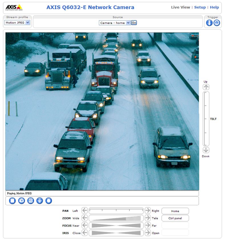
Access the video stream
The Live View page of the network camera is displayed, with links to the Setup tools, which allow
you to customize the camera.
If required, click Yes to install AMC (AXIS Media Control), which allows viewing of the video stream
in Internet Explorer. You will need administrator rights on the computer to do this.
If required, click the link to install missing decoders.
Note:
To install AMC in Windows Vista, you must run Internet Explorer as administrator. Right-
click the Internet Explorer icon and select Run as administrator.
Setup - Provides all the Help - Displays online help
tools for configuring the on all aspects of using the
camera to requirements. camera.AXIS Q6032-E/Q6034-E/Q6035-E Installation Guide Page 17
Other methods of setting the IP address
The table below shows the other methods available for setting or discovering the IP address. All
methods are enabled by default, and all can be disabled.
Use in operating Notes
system
UPnP™ Windows When enabled on your computer, the camera is automatically
detected and added to “My Network Places.”
Bonjour MAC OSX Applicable to browsers with support for Bonjour. Navigate to the
(10.4 or later) Bonjour bookmark in your browser (e.g. Safari) and click on the
ENGLISH
link to access the camera’s web pages.
AXIS Dynamic DNS All A free service from Axis that allows you to quickly and simply
Service install your camera. Requires an Internet connection with no
HTTP proxy. See www.axiscam.net for more information.
ARP/Ping All See below. The command must be issued within 2 minutes of
connecting power to the camera.
DHCP server All To view the admin pages for the network DHCP server, see the
server’s own documentation.
AXIS Video Hosting System (AVHS)
The camera can also be connected to an AVHS service for hosted video. If you have subscribed to an
AVHS service, follow the instructions in the Service Provider’s Installation Guide. For more
information and help to find a local AVHS Service Provider, go to www.axis.com/hosting
A Camera owner authentication key is supplied with this product. The key is associated with the
camera’s unique serial number (S/N) as shown on the top of the label.
Note:
Save the key for future reference.Page 18 AXIS Q6032-E/Q6034-E/Q6035-E Installation Guide Set the IP address with ARP/Ping 1. Acquire an IP address on the same network segment your computer is connected to. 2. Locate the serial number (S/N) on the product label on the camera. 3. Open a command prompt on your computer and enter the following commands: Windows syntax: Windows example: arp -s arp -s 192.168.0.125 00-40-8c-18-10-00 ping -l 408 -t ping -l 408 -t 192.168.0.125 UNIX/Linux/Mac syntax: UNIX/Linux/Mac example: arp -s temp arp -s 192.168.0.125 00:40:8c:18:10:00 temp ping -s 408 ping -s 408 192.168.0.125 4. Check that the network cable is connected to the camera and then start/restart the camera, by disconnecting and reconnecting power. 5. Close the command prompt when you see ‘Reply from 192.168.0.125: ...’ or similar. 6. In your browser, type in http:// in the Location/Address field and press Enter on your keyboard. Notes: • To open a command prompt in Windows: from the Start menu, select Run... and type cmd. Click OK. • To use the ARP command in Windows Vista, right-click the command prompt icon and select Run as administrator. • To use the ARP command on a Mac OS X, use the Terminal utility in Application > Utilities.
AXIS Q6032-E/Q6034-E/Q6035-E Installation Guide                                                   Page 19

Electrical specifications
 Product                  Function                          Description
 AXIS Q6032-E             High Power over Ethernet          50-57 V DC, 50 W (max.)
 AXIS Q6034-E                                               (4-pair powering)
 AXIS Q6035-E

 Product                  Function                          Description
 AXIS T8124               Input Voltage                     100 - 240 V AC (50-60 Hz)
                          Input Current                     1.5 A (max.)

                                                                                                            ENGLISH
                          Input Power                       74 VA
                          Available Output Power            60 W (max.)
                          Nominal Output Voltage            55 V DC

Status indicators
Product                   Color           Indication

AXIS Q6032-E              Unlit           Steady connection/normal operation
AXIS Q6034-E
                          Amber           Steady for system initiating. Flashes during firmware upgrade
AXIS Q6035-E
                                          or reset to factory default.
                          Amber/red       No network connection
                          Red             Firmware upgrade failure
                          Green           Steady for 10 sec. after successful restart

Unit           LED        Color           Indication

AXIS T8124     Port       Unlit           No camera connected
                          Amber           Insufficient power for camera and heater. Check cable
                          Flashing        Power overload
                          Green           Camera connected, normal behavior
               AC input   Steady green    AC power connected
Page 20 AXIS Q6032-E/Q6034-E/Q6035-E Installation Guide
Resetting to the Factory Default Settings
To reset the camera to the original factory default settings, use the Control button and the Power
button on the side of the camera. This will reset all parameters, including the IP address, to the
Factory Default settings:
1. Remove the dome ring and dome cover, this will automatically disconnect power from the
camera.
2. Press and hold the Control button and the Power button at the same time.
3. Continue to hold down the Control button and the Power button until the Status indicator
flashes amber (this may take up to 15 seconds).
4. Release the Control button. When the Status indicator changes to green (which may take up to
1 minute) the process is complete and the camera has been reset. The unit now has the default
IP address 192.168.0.90
Note: The Status indicator will display green for 10 seconds only. After that it will be unlit.
Refer to the Status indicator table on page 19 for more information.
5. Release the Power button.
6. Replace the dome ring and dome cover, this will automatically reconnect power to the camera.
7. Re-assign the IP address, using one of the methods described Assign an IP address, on page 11.
It is also possible to reset parameters to the original factory default settings via the web interface.
For more information, please see the online help or the User Manual available from the AXIS
Network Video Product CD supplied with this product.
Accessing the camera from the Internet
Once installed, your network camera is accessible on your local network (LAN). To access the
camera from the Internet, network routers must be configured to allow incoming traffic, which is
usually done on a specific port.
• HTTP port (default port 80) for viewing and configuration
• RTSP port (default port 554) for viewing H.264 video streams
Please refer to the documentation for your router for further instructions. For more information on
this and other topics, visit the Axis Support Web at www.axis.com/techsup
Further information
The User Manual is available from the Axis Web site at www.axis.com or from the Axis Network
Video Product CD supplied with this product.
Tip!
Visit www.axis.com/techsup to check if there is updated firmware available for your
network camera. To see the currently installed firmware version, see Setup > About.Mesures de sécurité
Lisez attentivement ce guide d’installation avant d’installer le produit. Conservez le guide d’installation pour une
utilisation ultérieure.
ATTENTION!
• Pour éviter d’endommager le produit Axis, utilisez l’emballage d’origine ou un emballage équivalent pour le
transporter.
• Conservez le produit Axis dans un environnement sec et aéré.
• Évitez d’exposer le produit Axis à des vibrations, des chocs ou une trop forte pression et ne l’installez pas
sur des supports instables, ou encore sur des surfaces ou des murs instables ou vibrants; cela risquerait de
l’endommager.
• Utilisez uniquement des outils à main pour l’installation du produit Axis: l’utilisation d’outils électriques ou
l’usage excessif de la force risquent de l’endommager.
• N’utilisez ni produits chimiques, ni substances caustiques, ni nettoyeurs aérosol. Utilisez un chiffon humide
pour le nettoyage.
• N’utilisez que des accessoires conformes aux caractéristiques techniques du produit. Ceux-ci peuvent être
fournis par Axis ou un fournisseur tiers.
• Utilisez uniquement des pièces de rechange fournies ou recommandées par Axis.
• Ne tentez pas de réparer le produit vous-même, contactez Axis ou votre revendeur Axis pour tout problème
de maintenance.
IMPORTANT!
• Ce produit Axis doit être utilisé conformément aux lois et réglementations locales en vigueur.
Remplacement des piles
Ce produit Axis nécessite une pile au lithium CR2032 de 3V pour l’alimentation de son horloge en temps réel
interne. Dans des conditions normales d’utilisation, cette pile est censée durer au moins 5ans. Si la pile est
faible, le fonctionnement de l’horloge en temps réel peut être affecté et entraîner sa réinitialisation à chaque
mise sous tension. Un message enregistré apparaît lorsque la pile doit être remplacée. Ne remplacez la pile que
lorsque cela est nécessaire.
Si la pile doit être remplacée, veuillez contacter www.axis.com/techsup pour obtenir de l’aide.
• Le remplacement incorrect de la pile peut entraîner un risque d’explosion.
• Remplacez la pile par une pile identique ou équivalente uniquement, en respectant les recommandations du
fabricant.
• Jetez les piles usagées conformément aux consignes du fabricant.
Nettoyage de la bulle du dôme
• Veillez à ne pas rayer ou endommager la bulle du dôme. Ne nettoyez pas la bulle du dôme si elle semble
propre à l’œil nu et ne frottez jamais sa surface. Un nettoyage excessif peut l’endommager.
• Pour le nettoyage général de la bulle du dôme, il est recommandé d’utiliser un savon ou un détergent
neutre sans solvant, non abrasif, avec de l’eau et un chiffon doux. Rincez abondamment avec de l’eau douce
et tiède. Séchez à l’aide d’un chiffon doux pour éviter les salissures d’eau.
• N’utilisez jamais de détergents forts, d’essence, de benzène ou d’acétone, etc. et évitez toute exposition
directe aux rayons du soleil ou à des températures élevées lors du nettoyage.AXIS Q6032-E/Q6034-E/Q6035-E Guide d'installation Page 23
AXIS Q6032-E/Q6034-E/Q6035-E
Guide d'installation
Ce guide d’installation explique comment installer la Caméra réseau à dôme
AXIS Q6032-E/Q6034-E/Q6035-E PTZ sur votre réseau. Pour toute autre question concernant
l’utilisation du produit, reportez-vous au manuel d’utilisation du produit, que vous trouverez sur le
CD joint ou sur le site www.axis.com
Procédure d’installation
1. Vérifiez que l’emballage contient bien tous les éléments répertoriés dans la liste ci-dessous.
2. Vue d’ensemble du matériel. Reportez-vous à la page 24.
3. Installation du matériel. Reportez-vous à la page 25.
FRANÇAIS
4. Attribution d’une adresse IP. Reportez-vous à la page 29.
5. Configuration du mot de passe. Reportez-vous à la page 32.
Contenu de l’emballage
Élément Modèles/variantes/remarques
Caméra réseau AXIS Q6032-E/Q6034-E/Q6035-E
Bulles des dômes Bulle transparente non fumée (prémontée)
Injecteur de puissance High PoE AXIS T8124 câble d’alimentation fourni (différent selon les pays)
Connecteur RJ45 Connecteur réseau norme IP66
Pare-soleil Bulle de protection en plastique, vis fournies
CD CD de la caméra vidéo réseau Axis comprenant la documentation,
les outils d’installation et des logiciels complémentaires
Documentation imprimée Guide d’installation de l’AXIS Q6032-E/Q6034-E/Q6035-E (le présent
document)
Document de garantie d’Axis
Étiquettes de numéro de série supplémentaires (2x)
Clé d’authentification AVHS
Accessoires en option Accessoires de montage AXIS T91A
Consultez le site à l’adresse www.axis.com pour plus d’informations sur les
accessoires disponiblesPage 24 AXIS Q6032-E/Q6034-E/Q6035-E Guide d'installation
Description du matériel
Trous de vis
Pare-soleil
Trous pour les supports de rack
Bouton marche/arrêt
Caméra (pour les valeurs d’usine
Radiateur par défaut uniquement)
Attention !
peut être
très chaud
Crochet pour fil
Supports de rack (3) de sécurité
Connecteur réseau
(PoE)
Logement de carte Bouton de
mémoire SD commande
Voyant d’état
Référence (P/N) et numéro de série (S/N).
Le numéro de série peut
être demandé pendant l’installation.
Vis de l'anneau Anneau Joint Anneau du dôme
métallique (4) métallique en caoutchouc
Vis de l’anneau
Bulle du dôme du dôme (4)
Bulle du dômeAXIS Q6032-E/Q6034-E/Q6035-E Guide d'installation Page 25
Installation du matériel
Préparation de l’installation
Lisez toutes les instructions avant de préparer l’installation de la caméra réseau. En effet, de
nombreuses étapes de cette préparation requièrent le retrait de l’anneau et de la bulle du dôme et il
serait plus judicieux de les effectuer ensemble.
• La caméra réseau est livrée avec un pare-soleil facultatif. Si nécessaire, suivez les
instructions décrites dans la section Fixation du pare-soleil (facultatif) ci-après pour
connecter le pare-soleil.
• La caméra réseau est fournie avec un bulle transparente (non fumée). Si nécessaire, suivez
les instructions décrites dans la section Replacement de la bulle du dôme fumée/non fumée
(facultatif) ci-après pour replacer la bulle du dôme.
• Une carte SD standard ou haute capacité (non fournie) est requise pour stocker des images
en local sur la caméra réseau. Suivez les instructions décrites dans la section Installation
FRANÇAIS
d’une carte SD (facultatif) ci-après pour retirer la bulle du dôme et installer la carte SD.
Fixation du pare-soleil (facultatif)
1. Glissez le pare-soleil sur les supports de rack de la caméra dôme.
2. Fixez le pare-soleil à l’aide des vis fournies (Torx T20).
Replacement de la bulle du dôme fumée/non fumée (facultatif)
! IMPORTANT !
Cette caméra dispose d'une membrane de déshumidification qui permet de maintenir de faibles
niveaux d'humidité dans le dôme. Pour éviter toute condensation, ne démontez pas la caméra s'il
pleut ou s'il fait humide.
1. Desserrez les quatre vis de l'anneau du dôme puis retirez ce dernier et la bulle du dôme ;
reportez-vous à l'illustration à la page 24.
2. Retirez les 4 vis de l'anneau métallique (reportez-vous à l'illustration à la page 24).
3. Retirez l’anneau métallique et l’anneau du dôme de la bulle en plastique.
4. Retirez le joint en caoutchouc et fixez-le sur la bulle du dôme choisi. Assurez-vous de bien fixer
le joint de manière à ce qu’il s’emboîte parfaitement avec la bulle du dôme.
5. Alignez le renflement de la bulle du dôme avec l'un des logotypes de l'anneau du dôme.
6. Fixez l’anneau métallique en serrant les 4 vis au maximum.
7. En cas d’installation de la carte SD, reportez-vous aux instructions décrites dans la section
Installation d’une carte SD (facultatif) ci-après.Page 26 AXIS Q6032-E/Q6034-E/Q6035-E Guide d'installation
8. Remettez en place l’anneau et la bulle du dôme, puis serrez les vis. Alignez bien le renflement
de la bulle du dôme avec le radiateur de la caméra.
Bulle du dôme
Radiateur
Remarque :
Veillez à ne pas rayer ou endommager la bulle du dôme. Laissez, si possible, la protection en
plastique sur la bulle du dôme jusqu’à la fin de l’installation.
Installation d’une carte SD (facultatif)
1. Desserrez les quatre vis de l’anneau du dôme puis retirez ce dernier et la bulle du dôme, voir
l’illustration à la page 24.
2. Insérez une carte SD (non fournie) dans le logement de carte SDHC (Secure Digital High
Capacity).
3. Remettez en place l’anneau et la bulle du dôme, puis serrez les vis. Alignez bien le renflement
de la bulle du dôme avec le radiateur de la caméra, voir l’illustration à la page 26.
Remarques :
La carte SD est automatiquement installée une fois insérée dans le logement de carte
SDHC. Il est cependant nécessaire de désinstaller la carte SD à partir des pages Web de la
caméra avant de la retirer. Choisissez Setup > System Options > Storage > SD Card
(Configuration > Options système > Stockage > Carte SD), puis cliquez sur Unmount
(Désinstaller). Pour plus d’informations, consultez le manuel de l’utilisateur, disponible sur
le CD du produit de vidéo sur IP AXIS, fourni avec le produit ou en téléchargement sur le
site Web www.axis.comAXIS Q6032-E/Q6034-E/Q6035-E Guide d'installation Page 27
Installation de la caméra réseau
! IMPORTANT !
Le design norme IP66 de la caméra nécessite l’utilisation des connecteurs RJ45 ou RJ45
compatible norme IP66 fournis.
1. Installez le support choisi (non inclus)
conformément aux instructions fournies avec le
support. S’il s’avère nécessaire de percer,
vérifiez que les forets, vis et chevilles à utiliser
sont appropriés pour le matériau. Consultez le Vis
Torx T30
site www.axis.com pour plus d'informations sur
les accessoires de montage disponibles.
2. Retirez la protection du connecteur réseau de
Fil de
FRANÇAIS
la caméra. Logements pour
sécurité
supports de rack
3. Acheminez le câble réseau et fixez le
Plaquette de fixation murale (exemple de montage,
connecteur RJ45 fourni. Reportez-vous aux
plaquette non incluse)
instructions fournies avec le connecteur pour
plus d’informations sur le câblage et le montage.
4. Accrochez la caméra au fil de sécurité du support.
5. Connectez le câble réseau et le connecteur RJ45 au connecteur réseau de la caméra.
6. Installez l’injecteur AXIS T8124, reportez-vous à la section Installez l'injecteur High PoE AXIS à
1 port AXIS T8124, à la page 28.
7. Vérifiez que les voyants lumineux sur l’injecteur indiquent les conditions correctes. Pour plus
d’informations, reportez-vous au tableau à la page 29.
8. Glissez les supports de rack de la caméra dans les logements du support, puis tournez la caméra.
9. Fixez la caméra réseau au support de fixation à l’aide des trois vis (Torx T30).Page 28 AXIS Q6032-E/Q6034-E/Q6035-E Guide d'installation
Installez l'injecteur High PoE AXIS à 1 port AXIS T8124
L’injecteur de puissance Axis T8124 High PoE permet aux produits vidéo Axis consommant une
quantité importante d’énergie de recevoir des données et de l’alimentation via le même câble
Ethernet. Procédez comme suit pour connecter l' AXIS T8124.
Remarque :
Axis peut garantir l’intégralité des fonctions pour le modèle AXIS T8124 uniquement, tout
autre périphérique High PoE n’est pas pris en charge.
1. Branchez l’AXIS T8124 (Données d’entrée) au commutateur réseau via un câble réseau standard.
2. Branchez l’AXIS T8124 (Données et alimentation de sortie) à la caméra réseau, via un câble
réseau déjà branché à la caméra.
3. Branchez l’AXIS T8124 sur une prise CA (100-240 V CA), à l’aide du câble d’alimentation fourni.
AXIS T8124 Données et
Indicateur alimentation de sortie Données d’entrée
de connexion
du port
Indicateur
de connexion
d’entrée CA
Caméra réseau Ethernet
Pour plus d’informations sur les voyants lumineux de l’injecteur, reportez-vous à la section
Attribution d’une adresse IP, à la page 29.
Remarque :
Utilisez toujours un câble réseau à paires torsadées blindé à usage extérieur pour la liaison
entre la caméra et le point terminal. Assurez-vous également que le point terminal soit
correctement mis à la terre. Les installations des caméras Axis à l’aide d’un câble réseau à
paires torsadées blindé et du point terminal correctement mis à terre ont été soumises à
des tests rigoureux, conformément aux niveaux de la norme relative à l’immunité de
l’industrie, notamment la protection contre les surtensions. Toute autre méthode
d’installation annule la garantie et expose le produit à des risques.AXIS Q6032-E/Q6034-E/Q6035-E Guide d'installation Page 29
Attribution d’une adresse IP
Aujourd’hui, la plupart des réseaux sont équipés d’un serveur DHCP qui attribue automatiquement
des adresses IP aux périphériques connectés. Si votre réseau ne possède pas de serveur DHCP, la
caméra réseau utilise l’adresse IP 192.168.0.90 comme adresse IP par défaut.
Si vous souhaitez paramétrer une adresse IP statique sous Windows, nous recommandons
l’utilisation de l’application AXIS IP Utility ou de l’application AXIS Camera Management. Selon le
nombre de caméras à installer, choisissez la méthode qui vous convient le mieux.
Ces deux applications gratuites sont disponibles sur le CD du produit de vidéo sur IP Axis fourni
avec ce produit. Vous pouvez également les télécharger à partir du site www.axis.com
Méthode Recommandée pour Système d’exploitation
AXIS IP Utility Une seule caméra Windows
Voir page 30 Petites installations
FRANÇAIS
AXIS Camera Management Plusieurs caméras Windows 2000
Voir page 31 Grandes installations Windows XP Pro
Installation sur un autre sous- Windows 2003 Server
réseau Windows Vista
Windows 7
Remarques :
• En cas d’échec de l’attribution d’adresse IP, vérifiez qu’aucun pare-feu ne bloque l’opération.
• Pour connaître les autres méthodes d’attribution ou de détection de l’adresse IP, par exemple sous
d’autres systèmes d’exploitation, reportez-vous à la page 35.Page 30 AXIS Q6032-E/Q6034-E/Q6035-E Guide d'installation
AXIS IP Utility : une seule caméra/petite installation
AXIS IP Utility détecte et affiche automatiquement les périphériques Axis présents sur votre réseau.
Cette application peut également être utilisée pour attribuer manuellement une adresse IP statique.
Notez que l’ordinateur exécutant l’application AXIS IP Utility doit se trouver sur le même segment
de réseau (sous-réseau physique) que la caméra réseau.
Détection automatique
1. Vérifiez que la caméra est connectée au réseau et qu’elle est sous tension.
2. Lancez AXIS IP Utility.
3. Lorsque l’icône de la caméra apparaît dans la fenêtre, double-cliquez dessus pour ouvrir la page
d’accueil correspondante.
4. Reportez-vous à la page 32 pour savoir comment configurer le mot de passe.
Attribution manuelle de l’adresse IP (facultatif)
1. Trouvez une adresse IP non utilisée sur le même segment de réseau que celui de votre
ordinateur.
2. Sélectionnez la caméra réseau dans la liste.
3. Cliquez sur le bouton Assign new IP address to the selected device (Attribuer une nouvelle
adresse IP au périphérique sélectionné) , puis saisissez l’adresse IP.
4. Cliquez sur le bouton Assign (Attribuer) et suivez les instructions qui s’affichent à l’écran. La
caméra doit être redémarrée dans les 2 minutes pour que la nouvelle adresse IP soit prise en
compte.
5. Cliquez sur le bouton Home Page (Page d’accueil) pour accéder aux pages Web de la caméra.
6. Reportez-vous à la page 32 pour savoir comment configurer le mot de passe.AXIS Q6032-E/Q6034-E/Q6035-E Guide d'installation Page 31
AXIS Camera Management : plusieurs caméras/grandes installations
AXIS Camera Management est capable de détecter automatiquement plusieurs dispositifs Axis,
d’afficher leur état de connexion, de gérer les mises à niveau des micrologiciels et de définir les
adresses IP.
Détection automatique
1. Vérifiez que la caméra est connectée au réseau et qu’elle est sous tension.
FRANÇAIS
2. Lancez AXIS Camera Management. Lorsque la caméra réseau apparaît dans la fenêtre, cliquez
sur le lien avec le bouton droit de la souris, puis sélectionnez Live View Home Page (Page
d’accueil – Vue en direct).
3. Reportez-vous à la page 32 pour savoir comment configurer le mot de passe.
Attribution d’une adresse IP à un seul périphérique
1. Sélectionnez la caméra réseau dans l’application AXIS Camera
Management, puis cliquez sur le bouton Assign IP (Attribuer une
adresse IP) .
2. Sélectionnez Assign the following IP address (Attribuer l’adresse IP
suivante) et saisissez l’adresse IP, le masque de sous-réseau et le
routeur par défaut que le périphérique utilisera.
3. Cliquez sur OK.
Attribution d’adresses IP à plusieurs périphériques
AXIS Camera Management accélère le processus d’attribution
d’adresses IP à plusieurs périphériques en suggérant des adresses IP
dans une plage spécifiée.
1. Sélectionnez les périphériques à configurer (il peut s’agir de
modèles différents), puis cliquez sur le bouton Assign IP
(Attribuer adresses IP) .
2. Sélectionnez Assign the following IP address range (Attribuer
la plage d’adresses IP suivante) et saisissez la plage d’adresses IP,
le masque de sous-réseau et le routeur par défaut que les périphériques utiliseront.
3. Cliquez sur Update (Mettre à jour). Les adresses IP suggérées sont énumérées sous le champ
New IP Addresses (Nouvelles adresses IP) et peuvent être modifiées en sélectionnant un
périphérique et en cliquant sur le bouton Edit (Modifier).
4. Cliquez sur OK.Page 32 AXIS Q6032-E/Q6034-E/Q6035-E Guide d'installation
Configuration du mot de passe
Pour accéder au produit, le mot de passe par défaut de l’administrateur, root, doit être configuré.
Pour ce faire, utilisez la boîte de dialogue Configure Root Password (Configurer le mot de passe
root) qui s’affiche lors du premier accès au réseau.
Pour éviter les écoutes électroniques lors de la configuration du mot de passe root, utilisez une
connexion HTTPS cryptée nécessitant un certificat HTTPS.
Remarque : Le protocole HTTPS (Hypertext Transfer Protocol over Secure Socket Layer) est utilisé pour
crypter le trafic entre les navigateurs Web et les serveurs. Le certificat HTTPS contrôle l’échange
crypté des informations.
Pour configurer le mot de passe avec une connexion HTTP standard, saisissez directement le mot de
passe dans la première boîte de dialogue représentée ci-dessous.
Pour configurer le mot de passe avec une connexion HTTPS cryptée, procédez comme suit :
1. Cliquez sur le bouton Create self-signed certificate (Créer un certificat autosigné).
2. Saisissez les informations demandées, puis cliquez sur OK. Le certificat est créé et le mot de
passe peut maintenant être configuré en toute sécurité. Tout le trafic entrant et sortant de la
caméra réseau est désormais crypté.
3. Saisissez un mot de passe, puis saisissez-le à nouveau pour confirmation. Cliquez sur OK. Le
mot de passe est maintenant configuré.
Pour créer une connexion HTTPS,
cliquez sur ce bouton.
Pour configurer directement le mot
de passe par le biais d’une connexion
cryptée, saisissez le mot de passeAXIS Q6032-E/Q6034-E/Q6035-E Guide d'installation Page 33
4. Pour vous connecter, saisissez le nom d’utilisateur « root » dans la boîte de dialogue à l’invite.
Remarque :le nom d’utilisateur par défaut de l’administrateur (root) ne peut pas être supprimé.
5. Saisissez le mot de passe de la manière indiquée ci-dessus et cliquez sur OK.
Remarque :si vous avez oublié votre mot de passe, vous devrez rétablir les paramètres d’usine
par défaut de votre caméra. Reportez-vous à la page 38.
6. AXIS Q6035-E: le mode de capture doit être
configuré lors du premier accès à la caméra
réseau. Sélectionnez le mode de capture
souhaité dans la liste déroulante et cliquez
sur OK.
Remarque:Vous pouvez modifier le mode de
capture ultérieurement dans les
pages web du produit, mais cela
réinitialisera la plupart des autres
paramètres. Pour plus
FRANÇAIS
d’informations, reportez-vous àPage 34 AXIS Q6032-E/Q6034-E/Q6035-E Guide d'installation
Accès au flux de données vidéo
La page Live View (Vidéo en direct) de la caméra réseau s’affiche, avec des liens vers les outils de
configuration, lesquels vous permettent d’adapter la caméra à vos besoins.
Si nécessaire, cliquez sur Yes (Oui) pour installer AMC (AXIS Media Control) afin de visualiser le flux
de données vidéo dans Internet Explorer. Pour ce faire, vous devrez être connecté à l’ordinateur
avec des droits d’administrateur.
Si nécessaire, cliquez sur le lien pour installer les décodeurs manquants.
Remarque :
Pour installer AMC sous Windows Vista, vous devez exécuter Internet Explorer en tant
qu’administrateur. Cliquez avec le bouton droit de la souris sur l’icône d'Internet Explorer et
sélectionnez Exécuter en tant qu’administrateur.
Setup (Configuration) : contient Help (Aide) : affiche
tous les outils nécessaires pour l’aide en ligne sur tout ce
configurer la caméra en qui a trait à l’utilisation
fonction de vos besoins. de la caméra.AXIS Q6032-E/Q6034-E/Q6035-E Guide d'installation Page 35
Autres méthodes de définition de l’adresse IP
Le tableau ci-dessous indique les autres méthodes permettant de configurer ou de détecter
l’adresse IP. Toutes les méthodes sont activées par défaut et peuvent être désactivées.
Utiliser sous le Remarques
système
d’exploitation
UPnP™ Windows Lorsque cette option est activée sur l’ordinateur, la caméra est
automatiquement détectée et ajoutée au dossier Favoris réseau.
Bonjour MAC OSX Pour les navigateurs compatibles avec Bonjour. Accédez au
(10.4 ou version signet de Bonjour dans votre navigateur (par exemple, Safari),
ultérieure) puis cliquez sur le lien pour accéder aux pages Web de la caméra.
AXIS Dynamic DNS Tous Service Axis gratuit permettant d’installer rapidement et
Service facilement votre caméra. Nécessite une connexion Internet sans
FRANÇAIS
proxy HTTP. Pour plus d’informations, rendez-vous sur
www.axiscam.net.
ARP/Ping Tous Voir ci-dessous. La commande doit être saisie dans les 2 minutes
suivant la mise sous tension de la caméra.
Serveur DHCP Tous Pour consulter les pages administratives du serveur DHCP réseau,
reportez-vous à la documentation du serveur.
AXIS Video Hosting System (AVHS)
La caméra peut aussi être connectée à un serveur AVHS pour les vidéos reçues. Si vous vous êtes
inscrit à un serveur AVHS, suivez les instructions décrites dans le Guide d’installation du fournisseur
de service. Pour obtenir des renseignements supplémentaires et trouver un fournisseur de service
AVHS, consultez le site www.axis.com/hosting
La Clé d’authentification du propriétaire de la caméra est inscrite sur la couverture arrière de ce
document. La clé est associée au numéro de série (S/N) unique de la caméra, comme décrit sur le
haut de l’étiquette.
Remarque :
Enregistrez la clé pour référence ultérieure.Vous pouvez aussi lire


