INSTALLATION GUIDE AXIS P3301 Fixed Dome Network Camera AXIS P3301-V Fixed Dome Network Camera AXIS P3304 Fixed Dome Network Camera AXIS P3304-V ...
←
→
Transcription du contenu de la page
Si votre navigateur ne rend pas la page correctement, lisez s'il vous plaît le contenu de la page ci-dessous
INSTALLATION GUIDE

AXIS P3301 Fixed Dome Network Camera

                                         ENGLISH
AXIS P3301-V Fixed Dome Network Camera

                                         FRANÇAIS
AXIS P3304 Fixed Dome Network Camera

AXIS P3304-V Fixed Dome Network Camera

                                         DEUTSCH
                                         ITALIANO
                                         ESPAÑOL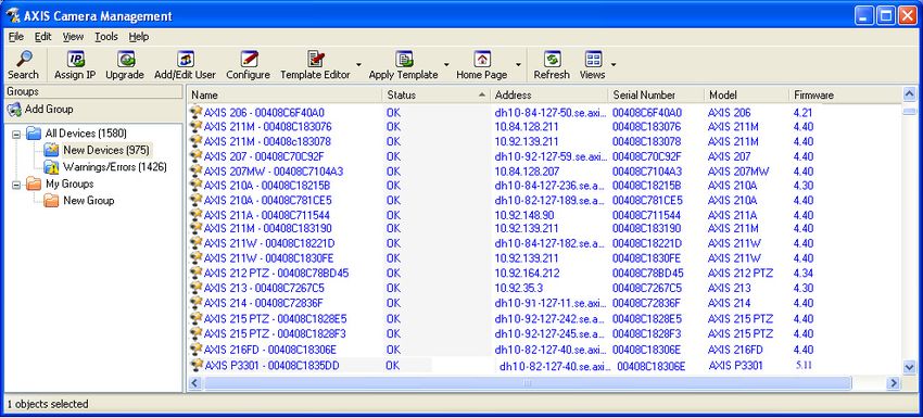
About this Document                                          Equipment Modifications
This document includes instructions for installing AXIS      This equipment must be installed and used in strict
P3301/P3304 Fixed Dome Network Cameras on your               accordance with the instructions given in the user
network. Previous experience of networking will be           documentation. This equipment contains no
beneficial when installing the product.                      user-serviceable components. Unauthorized equipment
                                                             changes or modifications will invalidate all applicable
Legal Considerations                                         regulatory certifications and approvals.
Video and audio surveillance can be prohibited by laws
that vary from country to country. Check the laws in         Liability
your local region before using this product for              Every care has been taken in the preparation of this
surveillance purposes.                                       document. Please inform your local Axis office of any
This product includes one (1) H.264 decoder license. To      inaccuracies or omissions. Axis Communications AB
purchase further licenses, contact your reseller.            cannot be held responsible for any technical or
                                                             typographical errors and reserves the right to make
Electromagnetic Compatibility (EMC)                          changes to the product and documentation without
This equipment generates, uses and can radiate radio         prior notice. Axis Communications AB makes no
frequency energy and, if not installed and used in           warranty of any kind with regard to the material
accordance with the instructions, may cause harmful          contained within this document, including, but not
interference to radio communications. However, there is      limited to, the implied warranties of merchantability
no guarantee that interference will not occur in a           and fitness for a particular purpose. Axis
particular installation.                                     Communications AB shall not be liable nor responsible
                                                             for incidental or consequential damages in connection
If this equipment does cause harmful interference to         with the furnishing, performance or use of this material.
radio or television reception, which can be determined
by turning the equipment off and on, the user is             RoHS
encouraged to try to correct the interference by one or      This product complies with both the European
more of the following measures: Re-orient or relocate        RoHS directive, 2002/95/EC, and the Chinese
the receiving antenna. Increase the separation between       RoHS regulations, ACPEIP.
the equipment and receiver. Connect the equipment to
an outlet on a different circuit to the receiver. Consult    WEEE Directive
your dealer or an experienced radio/TV technician for        The European Union has enacted a Directive
help. Shielded (STP) network cables must be used with        2002/96/EC on Waste Electrical and Electronic
this unit to ensure compliance with EMC standards.           Equipment (WEEE Directive). This directive is
USA - This equipment has been tested and found to            applicable in the European Union member
comply with the limits for a Class B computing device        states.
pursuant to Subpart B of Part 15 of FCC rules, which are     The WEEE marking on this product (see right) or its
designed to provide reasonable protection against such       documentation indicates that the product must not be
interference when operated in a commercial                   disposed of together with household waste. To prevent
environment. Operation of this equipment in a                possible harm to human health and/or the environment,
residential area is likely to cause interference, in which   the product must be disposed of in an approved and
case the user at his/her own expense will be required to     environmentally safe recycling process. For further
take whatever measures may be required to correct the        information on how to dispose of this product correctly,
interference.                                                contact the product supplier, or the local authority
                                                             responsible for waste disposal in your area.
Canada - This Class B digital apparatus complies with        Business users should contact the product supplier for
Canadian ICES-003.                                           information on how to dispose of this product correctly.
                                                             This product should not be mixed with other commercial
Europe -       This digital equipment fulfills the           waste. For more information, visit
requirements for radiated emission according to limit B      http://www.axis.com/corporate/about/environment.htm
of EN55022, and the requirements for immunity
according to EN55024 residential and commercial              Support
industry.                                                    Should you require any technical assistance, please
Japan - This is a class B product based on the standard      contact your Axis reseller. If your questions cannot be
of the Voluntary Control Council for Interference from       answered immediately, your reseller will forward your
Information Technology Equipment (VCCI). If this is used     queries through the appropriate channels to ensure a
near a radio or television receiver in a domestic            rapid response. If you are connected to the Internet, you
environment, it may cause radio interference. Install and    can:
use the equipment according to the instruction manual.       • download user documentation and firmware updates
                                                             • find answers to resolved problems in the FAQ database.
Australia - This electronic device meets the                   Search by product, category, or phrases
requirements of the Radio communications                     • report problems to Axis support by logging in to your
(Electromagnetic Compatibility) Standard AS/NZS                private support area.
CISPR22.                                                     AXIS P3301/P3304 Fixed Dome Network Cameras
                                                             uses a 3.0V CR2032 Lithium battery, for more
                                                             information please see page 73.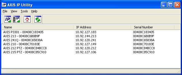
AXIS P3301/P3304 Installation Guide                                                                Page 3

AXIS P3301/P3304 Installation Guide
This installation guide provides instructions for installing the AXIS P3301/AXIS P3301-V/AXIS
P3304/AXIS P3304-V Fixed Dome Network Camera on your network. These cameras will be jointly
referred to as AXIS P3301/P3304. The information in this manual applies to all the cameras unless
specified otherwise. For all other aspects of using the product, please see the User’s Manual,
available on the CD included in this package, or from www.axis.com/techsup

Installation steps

                                                                                                            ENGLISH
1.   Check the package contents against the list below.
2.   Hardware overview. See page 4.
3.   Install the hardware. See page 5.
4.   Assign an IP address. See page 6.
5.   Set the password. See page 9.                                  Important!
                                                                    This product must be used in
6.   Adjust the focus. See page 11.
                                                                    compliance with local laws and
7.   Complete the installation. See page 11.                        regulations.

     Package contents

Item                         Models/variants/notes

Fixed Dome Network camera    AXIS P3301 - Tamper-resistant casing
                             AXIS P3301-V - Vandal-resistant casing
                             AXIS P3304 - Tamper-resistant casing
                             AXIS P3304-V - Vandal-resistant casing
Terminal block connector     4-pin connector block for connecting external devices to the I/O terminal
                             connector
Mounting kit                 Screwdriver for tamper-proof screws
                             Tamper-proof screws
                             Drill template
CD                           AXIS Network Video Product CD, including product documentation,
                             installation tools and other software
Printed Materials            AXIS P3301/P3304 Installation Guide (this document)
                             Axis Warranty Document
Page 4 AXIS P3301/P3304 Installation Guide
Hardware overview
16mm cable conduit
(not supplied) fitted
to AXIS P3301/P3304
Cover plates
Control button I/O terminal
connector
see page 13
Power connector
see page 13
Power Network connector
indicator LED see page 13 Audio out Audio in
Network
indicator LED
Status
indicator Product ID & Serial number (S/N).
LED The serial number may be
required during the installation.
Microphone
Dimensions
HxWxD = 94 x 144 x 132mm (3.7" x 5.7" x 5.2")
Weight AXIS P3301 = 425g (0.94 lb) power supply excl.
Weight AXIS P3301-V = 580g (1.28 lb) power supply excl.
Weight AXIS P3304 = 435g (0.96 lb) power supply excl.
Weight AXIS P3304-V = 590 g (1.30 lb) power supply excl.AXIS P3301/P3304 Installation Guide Page 5
Install the hardware
! IMPORTANT! - The casing of the AXIS P3301-V/AXIS P3304-V is not approved for
outdoor use - the product may only be installed in indoor environments.
Mount the camera
The AXIS P3301/P3304 can be mounted with the cables routed through the wall/ceiling, or from
ENGLISH
above or below. There are cover plates for the openings on both sides of the dome cover.
The AXIS P3301/P3304 can also be fitted with a metal conduit for protecting the cabling when
connected via the side openings. See the illustrations on page 4.
1. Using the drill template, drill two holes in the ceiling/wall. Ensure the camera is positioned so
that the tamper-proof screws can be tightened using the supplied screwdriver.
2. Route the required cables. See Connect the cables, on page 6 for details.
3. Fasten the camera unit to a ceiling or wall, using screws and plugs appropriate for the ceiling/
wall material.
4. Proceed to Connect the cables, on page 6.
Mounting on a drop ceiling
To mount the AXIS P3301/P3304 on a drop ceiling, check that the ceiling material is sturdy enough
to hold the weight of the camera.
The camera can also be secured using a plate or board that better carries the weight of the camera,
and which is more suitable for securing the screws.
Plate or board
Ceiling
AXIS P3301/AXIS P3304
Screws
The AXIS P3301/P3304 network camera can also be mounted using the Drop Ceiling Mount, which
allows the camera to be mounted more discreetly. Please see www.axis.com for all available
mounting accessories.Page 6 AXIS P3301/P3304 Installation Guide
Connect the cables
1. Optionally connect external input/output devices, e.g. alarm devices. See page 13 for informa-
tion on the terminal connector pins.
2. Optionally connect an active speaker and/or external microphone.
3. Connect the camera to the network using a shielded network cable.
4. Connect power, using one of the methods listed below:
• PoE (Power over Ethernet, Class 2). If available, this is automatically detected when the
network cable is connected.
• Connect the supplied indoor power supply to the power connector on the camera.
5. Check that the indicator LEDs indicate the correct conditions. See the table on page 14 for
further details. Note that some LEDs can be disabled and may be unlit.
Assign an IP address
Follow these instructions to assign an IP address or see page 12 for other methods of connecting the
AXIS P3301/P3304 network camera to the Internet.
Assign an IP address
Most networks today have a DHCP server that automatically assigns IP addresses to connected
devices. If your network does not have a DHCP server the AXIS P3301/P3304 will use 192.168.0.90
as the default IP address.
If you would like to assign a static IP address, the recommended method in Windows is either AXIS
IP Utility or AXIS Camera Management. Depending on the number of cameras you wish to install,
use the method that best suits your purpose.
Both of these free applications are available on the Axis Network Video Product CD supplied with
this product, or they can be downloaded from www.axis.com/techsup
Method Recommended for Operating system
AXIS IP Utility Single camera Windows
See page 7 Small installations
AXIS Camera Management Multiple cameras Windows 2000
See page 8 Large installations Windows XP Pro
Installation on a different subnet Windows 2003 Server
Windows Vista
Windows 7
Notes:
• If assigning the IP address fails, check that there is no firewall blocking the operation.
• For other methods of assigning or discovering the IP address of the AXIS P3301/P3304 network
camera, e.g. in other operating systems, see page 12.AXIS P3301/P3304 Installation Guide Page 7
AXIS IP Utility - single camera/small installation
AXIS IP Utility automatically discovers and displays Axis devices on your network. The application
can also be used to manually assign a static IP address.
ENGLISH
Note that the computer running AXIS IP Utility must be on the same network segment (physical
subnet) as the AXIS P3301/P3304 network camera.
Automatic discovery
1. Check that the AXIS P3301/P3304 network camera is connected to the network and that power
has been applied.
2. Start AXIS IP Utility.
3. When the camera appears in the window, double-click it to open its home page.
4. See page 9 for instructions on how to assign the password.
Assign the IP address manually (optional)
1. Acquire an unused IP address on the same network segment as your computer.
2. Select the AXIS P3301/P3304 network camera in the list.
3. Click the button Assign new IP address to the selected device and enter the IP address.
4. Click the Assign button and follow the on-screen instructions. Note that the camera must be
restarted within 2 minutes for the new IP address to be set.
5. Click the Home Page button to access the camera’s web pages.
6. See page 9 for instructions on how to set the password.
Note:
AXIS P3301-V and AXIS P3304-V will display in AXIS IP Utility as AXIS P3301 and AXIS
P3304.Page 8 AXIS P3301/P3304 Installation Guide
AXIS Camera Management - multiple cameras/large installations
AXIS Camera Management can automatically discover multiple Axis devices, show connection
status, manage firmware upgrades and set IP addresses.
Automatic discovery
1. Check that the camera is connected to the network and that power has been applied.
2. Start AXIS Camera Management. When the AXIS P3301/P3304 network camera appears in the
window, double-click it to open the camera’s home page.
3. See page 9 for instructions on how to set the password.
Assign an IP address in a single device
1. Select the AXIS P3301/P3304 network camera in AXIS Camera
Management and click the Assign IP button.
2. Select Assign the following IP address and enter the IP
address, subnet mask and default router the device will use.
3. Click the OK button.
Assign IP addresses in multiple devices
AXIS Camera Management speeds up the process of assigning IP
addresses to multiple devices, by suggesting IP addresses from a
specified range.
1. Select the devices you wish to configure (different models can
be selected) and click the Assign IP button.
2. Select Assign the following IP address range and enter the
range of IP addresses, the subnet mask and default router the
devices will use.
3. Click the OK button.
Note:
AXIS P3301-V and AXIS P3304-V will display in AXIS Camera Management as AXIS P3301
and AXIS P3304.AXIS P3301/P3304 Installation Guide Page 9
Set the password
To gain access to the product, the password for the default administrator user root must be set. This
is done in the ‘Configure Root Password’ dialog, which is displayed when the AXIS P3301/P3304 is
accessed for the first time.
To prevent network eavesdropping when setting the root password, this can be done via an
encrypted HTTPS connection, which requires an HTTPS certificate (see note below).
To set the password via a standard HTTP connection, enter it directly in the first dialog shown
below.
ENGLISH
To set the password via an encrypted HTTPS connection, follow these steps:
1. Click the Create self-signed certificate button.
2. Provide the requested information and click OK. The certificate is created and the password can
now be set securely. All traffic to and from the AXIS P3301/P3304 network camera is encrypted
from this point on.
3. Enter a password and then re-enter it to confirm the spelling. Click OK. The password has now
been configured.
To create an HTTPS connection,
start by clicking this button.
To configure the password directly
via an unencrypted connection, enter
the password here.
4. To log in, enter the user name “root” in the dialog as requested
Note: The default administrator user name root cannot be deleted.
5. Enter the password as set above, and click OK.Page 10 AXIS P3301/P3304 Installation Guide
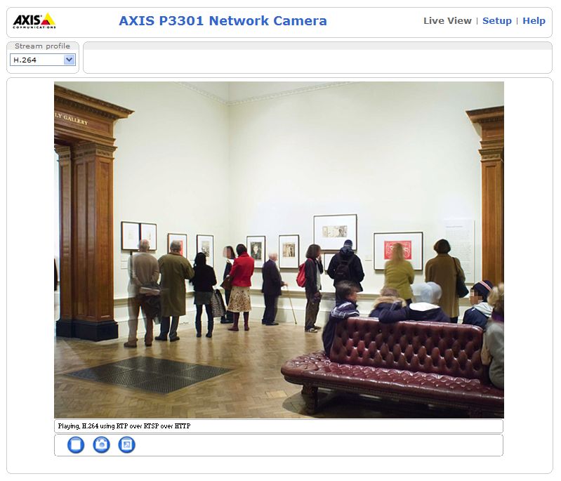
Access the video stream
The Live View page of the AXIS P3301/P3304 network camera is displayed, with links to the Setup
link menus, which allow you to customize the camera.
If required, click Yes to install AMC (AXIS Media Control), which allows viewing of the video stream
in Internet Explorer. You will need administrator rights on the computer to do this.
Setup - Provides all the tools for configuring
the camera to requirements.
Help - Displays
online help on all
aspects of using
the camera.
Notes:
• HTTPS (Hypertext Transfer Protocol over Secure Socket Layer) is a protocol used to encrypt the traffic
between web browsers and servers. The HTTPS certificate controls the encrypted exchange of
information.
• The default administrator user root cannot be deleted.
• If the password for root is lost or forgotten, the AXIS P3301/P3304 network camera must be reset
to the factory default settings. See Resetting to the Factory Default Settings, on page 15.AXIS P3301/P3304 Installation Guide Page 11
Adjust the image and focus
Open the Live View page in the web interface and make the following adjustments to the camera:
1. Loosen the locking screw and tilt adjust-
ment screws.
Locking screw
2. Turn the lens to the desired position.
3. Once satisfied, gently tighten the locking
screw and tilt adjustment screws to
secure the camera’s position.
4. Turn the image balance ring to set the
ENGLISH
Image
horizontal position. balance
5. Open the Focus Adjustment page in the ring
Web interface under Basic Configuration
> Focus and follow the on-screen Tilt adjustment
instructions. Use the image window to screw
adjust the focus and zoom. (on each side)
6. To set the focus and zoom, loosen the Focus puller Zoom puller
zoom and focus pullers anti-clockwise
and rotate the rings.
7. Lock the focus and zoom pullers in
position by rotating the screws clockwise.
Note:
Due to the dome’s refraction, the image may appear slightly out of focus once the dome
has been placed. Focus on an object slightly closer than the intended area to compensate
for this.
The image can also be fine-tuned for low light conditions.
Go to Setup > Video & Audio > Camera Settings in the camera’s web interface and see the online
help for more information.
Complete the installation
1. Rotate the black protective shield inside the dome casing to match the camera’s position.
2. Clean the dome with a dry soft cloth to remove dust and finger prints and use a blower to
remove dust from the lens.
3. Mount the dome casing using the supplied tamper-proof screws and screw driver.
4. Now that the dome is in place, double-check that the camera is properly focused.
5. The installation is now complete.Page 12 AXIS P3301/P3304 Installation Guide
Other methods of setting the IP address
The table below shows the other methods available for setting or discovering the IP address. All
methods are enabled by default, and all can be disabled.
Use in operating Notes
system
AVHS Service All To connect the camera to an AVHS server, refer to the server pro-
Connection vider’s Installation guide. For information and help to find a local
AVHS Service Provider go to www.axis.com
AXIS Dynamic DNS All A free service from Axis that allows you to quickly and simply
Service install your camera. Requires an Internet connection with no
HTTP proxy. See www.axiscam.net for more information.
ARP/Ping All See below. The command must be issued within 2 minutes of
connecting power to the camera.
UPnP™ Windows When enabled on your computer, the camera is automatically
(ME or XP) detected and added to “My Network Places.”
Bonjour MAC OSX Applicable to browsers with support for Bonjour. Navigate to the
(10.4 or later) Bonjour bookmark in your browser (e.g. Safari) and click on the
link to access the camera’s web pages.
DHCP server All To view the admin pages for the network DHCP server, see the
server’s own documentation.
Set the IP address with ARP/Ping
1. Acquire an IP address on the same network segment your computer is connected to.
2. Locate the serial number (S/N) on the AXIS P3301/P3304 network camera label.
3. Open a command prompt on your computer and enter the following commands:
Windows syntax: Windows example:
arp -s arp -s 192.168.0.125 00-40-8c-18-10-00
ping -l 408 -t ping -l 408 -t 192.168.0.125
UNIX/Linux/Mac syntax: UNIX/Linux/Mac example:
arp -s temp arp -s 192.168.0.125 00:40:8c:18:10:00 temp
ping -s 408 ping -s 408 192.168.0.125
4. Check that the network cable is connected to the camera and then start/restart the camera, by
disconnecting and reconnecting power.
5. Close the command prompt when you see ‘Reply from 192.168.0.125: ...’ or similar.
6. In your browser, type in http:// in the Location/Address field and press Enter on
your keyboard.
Notes:
• To open a command prompt in Windows: from the Start menu, select Run... and type cmd. Click OK.
• To use the ARP command on a Mac OS X, use the Terminal utility in Application > Utilities.AXIS P3301/P3304 Installation Guide Page 13
Unit connectors
Network connector - RJ-45 Ethernet connector. Supports Power over Ethernet. Using shielded
cables is recommended.
Power connector - Mini DC connector. 5.1V DC, max 4.0W. See product label for ± connection.
Audio in - 3.5mm input for a mono microphone, or a line-in mono signal (left channel is used from
a stereo signal).
Audio out - Audio output (line level) that can be connected to a public address (PA) system or an
active speaker with a built-in amplifier. A pair of headphones can also be attached. A stereo
ENGLISH
connector must be used for the audio out.
I/O terminal connector - Used in applications for e.g. motion detection,
event triggering, time lapse recording and alarm notifications. It provides the
interface to:
1 2 3 4
• 1 transistor output - For connecting external devices such as relays
and LEDs. Connected devices can be activated by the VAPIX Applica-
tion Programming Interface (API), by the output buttons on the Live View page or by an
Event Type. The output will show as active (shown under Event Configuration > Port Sta-
tus) if the alarm device is activated.
• 1 digital input - An alarm input for connecting devices that can toggle between an open
and closed circuit, for example: PIRs, door/window contacts, glass break detectors, etc.
When a signal is received the state changes and the input becomes active (shown under
Event Configuration > Port Status).
• Auxiliary power and GND
Function Pin Notes Specifications
GND 1 Ground
3.3V DC 2 Can be used to power auxiliary equipment. Max. load = 50mA
Power Note: This pin can only be used as power out.
Digital 3 Connect to GND to activate, or leave floating Min. input= - 40V DC
Input (or unconnected) to deactivate. Max. input= + 40V DC
Digital 4 Uses an open-drain NFET transistor with the Max. load = 100mA
Output source connected to GND. If used with an Max voltage = + 40V DC
external relay, a diode must be connected in
parallel with the load, for protection against
voltage transients.Page 14 AXIS P3301/P3304 Installation Guide
Connection diagram
AXIS P3301/-V/AXIS P3304/-V
1
o
e.g. push button
3.3V
max. 50mA 2
o
3
o
D 4
o
G
S
LED indicators
LED Color Indication
Network Green Steady for connection to a 100 Mbit/s network. Flashes for network activity.
Amber Steady for connection to 10 Mbit/s network. Flashes for network activity.
Unlit No network connection.
Status Green Steady green for normal operation.
Note: The Status LED can be configured to be unlit during normal operation, or to
flash only when the camera is accessed. To configure, go to Setup > System
Options > LED. See the online help files for more information.
Amber Steady during startup, during reset to factory default or when restoring settings.
Red Slow flash for failed upgrade.
Power Green Normal operation.
Amber Flashes green/amber during firmware upgrade.AXIS P3301/P3304 Installation Guide Page 15
Resetting to the Factory Default Settings
This will reset all parameters, including the IP address, to the Factory Default settings:
1. Disconnect power from the camera.
2. Press and hold the Control button and reconnect power.
3. Keep the Control button pressed until the Power indicator flashes amber (this may take up to
15 seconds).
4. Release the Control button. When the Power indicator displays green (which can take up to 1
minute) the process is complete and the camera has been reset.
5. Re-assign the IP address, using one of the methods described in this document.
ENGLISH
It is also possible to reset parameters to the original factory default settings via the web interface.
For more information, please see the online help or the user’s manual.
Accessing the camera from the Internet
Once installed, your AXIS P3301/P3304 is accessible on your local network (LAN). To access the
camera from the Internet, network routers must be configured to allow incoming traffic, which is
usually done on a specific port
• HTTP port (default port 80) for viewing and configuration
• RTSP port (default port 554) for viewing H.264 video streams
Please refer to the documentation for your router for further instructions. For more information on
this and other topics, visit the Axis Support Web at www.axis.com/techsup
Further information
The user’s manual is available from the Axis Web site at www.axis.com or from the Axis Network
Video Product CD supplied with this product.
Tip!
Visit www.axis.com/techsup to check if there is updated firmware available for your AXIS
P3301/P3304 network camera. To see the currently installed firmware version, see Setup >
About.AXIS P3301/P3304 Guide d'installation Page 17
AXIS P3301/P3304 Guide d'installation
Ce guide d'installation vous explique comment installer la AXIS P3301/AXIS P3301-V / AXIS P3304/
AXIS P3304-V Caméra réseau à dôme fixe sur votre réseau. Pour d'autres informations sur
l'utilisation de ce produit, consultez le manuel de l'utilisateur, disponible sur le CD fourni, ou visitez
le site www.axis.com/techsup.
Étapes de l'installation
1. Vérifiez le contenu de la livraison à l'aide de la liste ci-dessous.
2. Présentation du matériel. Reportez-vous à la page 18.
3. Installez le matériel. Reportez-vous à la page 19.
4. Paramétrez une adresse IP. Reportez-vous à la page 20.
5. Définissez le mot de passe. Reportez-vous à la page 23. Important !
FRANÇAIS
Ce produit doit être utilisé
6. Réglez la mise au point. Reportez-vous à la page 25.
conformément aux lois et
7. Terminez l'installation. Reportez-vous à la page 25. dispositions locales en vigueur.
Contenu de l'emballage
Article Modèles/variantes/remarques
Caméra réseau à dôme fixe AXIS P3301 - Boîtier inviolable
AXIS P3301-V - Boîtier anti-effraction
AXIS P3304 - Boîtier inviolable
AXIS P3304-V - Boîtier anti-effraction
Connecteur pour terminaux Connecteur 4 broches pour la connexion d'équipements externes au
connecteur
E/S
Kit de montage Tournevis pour vis inviolables
Vis inviolables
Gabarit de perçage
CD CD de la caméra vidéo réseau Axis comprenant la documentation,
les outils d'installation et les autres logiciels
Documentation Guide d'installation de la caméra AXIS P3301/P3304 (le présent document)
Document de garantie d'AxisPage 18 AXIS P3301/P3304 Guide d'installation
Présentation du matériel
conduit de câbles 16 mm
(non fourni) installé
AXIS P3301/P3304
Plaques
d'obturation
Bouton de
commande
Connecteur pour
Connecteur terminaux E/S
d’alimentation Reportez-vous à
Reportez-vous à la page 28
la page 28
Sortie Entrée
Témoin DEL Connecteur audio audio
d’alimentation deréseau
Reportez-vous
Témoin DEL réseau à la page 28
ID du produit et numéro de série (S/N).
Témoin Le numéro de série peut
DEL être demandé pendant l'installation.
d'état
Microphone
Dimensions
H x L x P = 94 x 144 x 132mm
Poids de la caméra AXIS P3301= 425g (0.94 lb) alimentation exclue
Poids de la caméra AXIS P3301-V = 580g (1.28 lb) alimentation exclue
Poids de la caméra AXIS P3304 = 435 g (0.96 lb) alimentation exclue
Poids de la caméra AXIS P3304-V = 590 g (1.30 lb) alimentation exclueAXIS P3301/P3304 Guide d'installation Page 19
Installation du matériel
! IMPORTANT ! - Le boitier de l'AXIS P3301-V/AXIS P3304-V n'est pas approuvé pour
une utilisation extérieure - Le produit doit être uniquement installé en intérieur.
Montage de la caméra
La caméra AXIS P3301/P3304 peut être montée avec les câbles d'alimentation et réseau acheminés
dans le mur/plafond, ou depuis le haut ou le bas. Vous disposez de plaques d'obturation pour les
ouvertures des deux côtés du capot du dôme.
La caméra AXIS P3301/P3304 peut être également dotée d'un conduit métallique pour protéger les
câbles lors d'une connexion par les ouvertures latérales. Consultez les figures de la page 18.
1. Avec le gabarit de perçage, percez deux trous dans le plafond/mur. Veillez à ce que la caméra
FRANÇAIS
soit positionnée de telle manière que les vis inviolables puissent être serrées à l'aide du
tournevis fourni.
2. Orientez les câbles nécessaires. Pour plus d'informations, consultez la section Branchement des
câbles, page 20.
3. Fixez la caméra au plafond ou au mur à l'aide des vis et des chevilles appropriées.
4. Passez à la section Branchement des câbles, page 20.
Montage sur plafond dur
Pour monter la caméra AXIS P3301/P3304 sur un plafond dur, vérifiez que le matériau du plafond
est assez solide pour supporter le poids de la caméra.
La caméral peut être également fixée à l'aide d'une plaque ou d'une planche qui supporte mieux le
poids de la caméra et qui peut être plus adaptée pour la fixation des vis.
Plaque ou
planche
Plafond
AXIS P3301/AXIS P3304
Vis
La caméra AXIS P3301/P3304 peut être également montée à l'aide du AXIS P3301/P3304 kit de
montage pour faux-plafond, qui permet un montage plus discret. Voir www.axis.com pour les
accessoires de montage disponibles.Page 20 AXIS P3301/P3304 Guide d'installation
Branchement des câbles
1. Si vous le souhaitez, connectez des dispositifs externes, par exemple des dispositifs d'alarme.
Reportez-vous à la page 28 pour plus d'informations sur les broches du connecteur pour
terminaux.
2. Si vous le souhaitez, connectez un haut-parleur actif et/ou un micro externe.
3. Connectez la caméra à votre réseau à l'aide d'un câble de réseau blindé.
4. Branchez l'alimentation à l'aide de l'une des méthodes reprises ci-dessous.
• PoE (Alimentation éléctrique par câble Ethernet, classe 2). Si disponible, ceci est
automatiquement détecté quand le câble résau est connecté.
• Branchez l'alimentation intérieure fournie au connecteur d'alimentation de la caméra.
5. Vérifiez que les témoins DEL indiquent les conditions correctes. Pour plus d'informations,
consultez le tableau à la page 29. Notez que certains témoins DEL peuvent être désactivés et
éteints.
Paramétrage d'une adresse IP
Aujourd'hui, la plupart des réseaux comportent un serveur DHCP qui paramètre automatiquement
des adresses IP aux dispositifs connectés. Si ce n'est pas le cas de votre réseau, la caméra AXIS
P3301/P3304 utilisera l'adresse IP par défaut 192.168.0.90.
Si vous souhaitez paramétrer une adresse IP statique, sous Windows nous recommandons
l'utilisation de l'application AXIS IP Utility ou de l'application AXIS Camera Management. Selon le
nombre de caméras à installer, utilisez la méthode qui vous convient le mieux.
Ces deux applications gratuites sont disponibles sur le CD de la caméra vidéo réseau Axis fourni
avec ce produit. Vous pouvez également les télécharger à partir du site www.axis.com/techsup.
Méthode Recommandée pour Système
d'exploitation
AXIS IP Utility Une seule caméra Windows
Voir page 21 Les petites installations
AXIS Camera Management Plusieurs caméras Windows 2000
Voir page 22 Les grandes installations Windows XP Pro
Installation sur un autre sous- Windows 2003 Server
réseau Windows Vista
Windows 7
Remarques :
• En cas d'échec de l'attribution de l'adresse IP, vérifiez qu'aucun pare-feu ne bloque l'opération.
• Pour connaître les autres méthodes d'affectation ou de repérage de l'adresse IP de la caméra AXIS
P3301/P3304, par exemple sur d'autres systèmes d'exploitation, reportez-vous à la page 26.AXIS P3301/P3304 Guide d'installation Page 21
AXIS IP Utility - Une seule caméra/petite installation
L'utilitaire AXIS IP Utility détecte et affiche automatiquement les périphériques Axis de votre
réseau. Cette application sert également à définir manuellement une adresse IP statique.
FRANÇAIS
Notez que l'ordinateur exécutant l'application AXIS IP Utility doit se trouver sur le même segment
de réseau (sous-réseau physique) que la caméra AXIS P3301/P3304.
Détection automatique
1. Vérifiez que la caméra AXIS P3301/P3304 est connectée au réseau et que l'alimentation est
activée.
2. Démarrez AXIS IP Utility.
3. Lorsque l'icône de la caméra apparaît dans la fenêtre, double-cliquez dessus pour ouvrir la page
d'accueil correspondante.
4. Consultez la page 23 pour savoir comment définir le mot de passe.
Paramétrage manuel de l'adresse IP (optionnel)
1. Trouvez une adresse IP inutilisée sur le même segment de réseau que celui de votre ordinateur.
2. Sélectionnez la caméra AXIS P3301/P3304 dans la liste.
3. Cliquez sur le bouton Assign new IP address to the selected device (Paramétrer une
nouvelle adresse IP de l'outil sélectionné) et entrez l'adresse IP.
4. Cliquez sur le bouton Assign (Paramétrer) et suivez les instructions à l'écran. La caméra doit
être redémarrée dans les 2 minutes pour que la nouvelle adresse IP soit prise en compte.
5. Cliquez sur le bouton Home Page (Page d'accueil) pour accéder aux pages Web de la caméra.
6. Consultez la page 23 pour savoir comment définir le mot de passe.
Remarque:
La caméra AXIS P3301-V et AXIS P3304-Vs'affiche dans l'application AXIS IP Utility sous le
nom AXIS P3301 et AXIS P3304.Page 22 AXIS P3301/P3304 Guide d'installation
AXIS Camera Management - Plusieurs caméras/grandes installations
AXIS Camera Management peut
détecter automatiquement
plusieurs dispositifs Axis, afficher
les états de connexion, gérer les
mises à niveau du microcode et
définir les adresses IP.
Détection automatique
1. Vérifiez que la caméra est
connectée au réseau et que
l'alimentation est activée.
2. Démarrez AXIS Camera Management. Double-cliquez sur l'icône de l'AXIS P3301/P3304
lorsqu'elle apparaît dans la fenêtre de façon à ouvrir la page d'accueil.
3. Consultez la page 23 pour savoir comment définir le mot de passe.
Paramétrage d'une adresse IP à un seul dispositif
1. Sélectionnez AXIS P3301/P3304 dans l'application AXIS
Camera Management, puis cliquez sur le bouton Assign IP
(Affecter une IP).
2. Sélectionnez Assign the following IP address (Affecter
l'adresse IP suivante) et saisissez l’adresse IP, le masque de
sous-réseau et le routeur par défaut que le dispositif utilisera.
3. Cliquez sur le bouton OK.
Paramétrage d'adresses IP à plusieurs dispositifs
AXIS Camera Management accélère le processus d'affectation
d'adresses IP sur plusieurs appareils en suggérant les adresses IP
parmi une plage spécifiée.
1. Sélectionnez les appareils à configurer (il peut s'agir de plusieurs
modèles), puis cliquez sur le bouton Assign IP (Affecter une
adresse IP).
2. Sélectionnez Assign the following IP address range (Affecter la
plage d'adresses IP suivante) et saisissez la plage d'adresses IP, le
masque de sous-réseau et le routeur par défaut que les dispositifs utiliseront.
3. Cliquez sur le bouton OK.
Remarque:
La caméra AXIS P3301-V et AXIS P3304-V s'affiche dans l'application AXIS Camera
Management sous le nom AXIS P3301 et AXIS P3304.AXIS P3301/P3304 Guide d'installation Page 23
Définition du mot de passe
Pour accéder à la caméra, le mot de passe root de l'administrateur par défaut doit être défini. Pour
ce faire, utilisez la boîte de dialogue Configure Root Password (Configurer mot de passe root) qui
s'affiche lors du premier AXIS P3301/P3304 accès à la caméra.
Pour éviter les écoutes électroniques lors de la définition du mot de passe root, utilisez une
connexion HTTPS cryptée nécessitant un certificat HTTPS (voir remarque ci-dessous).
Pour définir le mot passe avec une connexion HTTP standard, entrez directement le mot de passe
dans la première boîte de dialogue affichée ci-dessous.
Pour définir le mot passe avec une connexion HTTPS cryptée, procédez comme suit :
1. Cliquez sur le bouton Create self-signed certificate (Créer un certificat autosigné).
2. Entrez les informations demandées, puis cliquez sur OK. Le certificat est créé et le mot de passe
peut être maintenant défini en toute sécurité. L'ensemble du trafic vers et depuis la caméra
AXIS P3301/P3304 est crypté à partir de ce moment.
FRANÇAIS
3. Entrez un mot de passe, puis entrez-le de nouveau pour confirmation. Cliquez sur OK. Le mot de
passe est alors configuré.
Pour créer une connexion HTTPS, cliquez sur
ce bouton.
Pour configurer directement le mot de passe via
une connexion cryptée, entrez le mot de passe à
cet endroit.
4. Pour vous connecter, saisissez le nom d'utilisateur « root » dans la boîte de dialogue lorsque
vous y êtes invité.
Remarque : le nom d'utilisateur par défaut de l'administrateur, à savoir root, ne peut pas être
supprimé.
5. Entrez le mot de passe comme expliqué ci-dessus, puis cliquez sur OK.Page 24 AXIS P3301/P3304 Guide d'installation
Accès au flux vidéo
La page Live View (Vidéo en direct) de la caméra AXIS P3301/P3304 s'affiche, avec des liens
vers les outils de configuration pour adapter la caméra à vos besoins.
Si nécessaire, cliquez sur Yes (Oui) pour installer AMC (Axis Media Control) afin de pouvoir
visualiser le flux vidéo dans Internet Explorer. Pour ce faire, vous devrez être connecté à votre
ordinateur avec les droits d'administrateur.
Setup (Configuration) : contient tous les outils
nécessaires pour adapter la caméra à vos besoins.
Help (Aide) :
affiche une aide
en ligne sur
l'utilisation de la
caméra.
Remarques :
• Le protocole HTTPS (Hypertext Transfer Protocol over Secure Socket Layer) est utilisé pour crypter le
trafic entre les navigateurs Web et les serveurs. Le certificat HTTPS contrôle l'échange crypté des
informations.
• Le mot de passe root de l'administrateur par défaut ne peut être supprimé.
• Si vous perdez ou oubliez le mot de passe root, les paramètres par défaut définis en usine de la
caméra AXIS P3301/P3304 doivent être rétablis. Reportez-vous à la section Rétablissement des
paramètres d'usine par défaut, page 30.AXIS P3301/P3304 Guide d'installation Page 25
Réglage de l'image et de la mise au point
Ouvrez la page Live View (Vidéo en direct) dans l'interface Internet et effectuez les réglages
suivants sur la caméra :
1. Désserrez la vis de verrouillage et les vis
Vis de verrouillage
de réglage de l'inclinaison.
2. Tournez l'objectif dans la position
souhaitée.
3. Une fois que vous avez terminé, serrez
Vis
délicatement la vis de verrouillage et les de réglage
vis de réglage de l'inclinaison pour bien de la balance
fixer la caméra.
Vis de réglage
4. Tournez la vis de réglage de la balance de l'inclinaison
pour définir la position horizontale. (de chaque côté)
5. Ouvrez la page Focus Adjustment
FRANÇAIS
Point Zoom
(Réglage et mise au point) de l'interface Mise au point
Web sous Basic Configuration > Focus de l'objectif
(Configuration de base - Mise au point)
et suivez les instructions à l'écran.
Utilisez la fenêtre d'image pour régler le zoom et la mise au point.
6. Pour régler le zoom et la mise au point, desserrez les commandes correspondantes en tournant
dans le sens inverse des aiguilles d'une montre, puis faites tourner les bagues.
7. Verrouillez les commandes de zoom et de mise au point en serrant les vis dans le sens des
aiguilles d'une montre.
Remarque:
Du fait de la réfraction du dôme, l'image peut apparaître légèrement floue une fois le dôme
installé. Mettez au point sur un objet legèrement plus proche que la zone cible pour
compenser ce défaut.
L'image peut également être ajustée en cas de faible éclairage.
Accédez à Setup > Video & Audio > Camera Settings (Configuration - Vidéo et image - Réglages
caméra) dans l'interface Web de la caméra et consultez l'aide en ligne pour plus d'informations.
Terminez l'installation
1. Tournez l'écran protecteur noir à l'intérieur du boîtier du dôme, conformément à la position de
la caméra.
2. Nettoyez le dôme avec un chiffon doux et sec pour enlever la poussière et les traces de doigt.
Dépoussiérez l'objectif avec un ventilateur.
3. Montez le boîtier du dôme à l'aide des vis inviolables et du tournevis fournis.
4. Une fois le dôme en place, faites une double vérification de la mise au point de la caméra.
5. L'installation est terminée.Page 26 AXIS P3301/P3304 Guide d'installation
Autres méthodes de définition de l'adresse IP
Le tableau ci-dessous indique les autres méthodes permettant de définir ou de déterminer l'adresse
IP. Toutes les méthodes sont activées par défaut et désactivables.
Système Remarques
d'exploitation
Service de Tout Pour connecter la caméra au serveur AVHS, consulter le guide
connection AVHS d´installation du fournisseur du serveur. Pour plus d´informations
et d´aides pour trouver un fournisseur local du service AVHS,
merci de vous connecter sur www.axis.com
AXIS Dynamic DNS Tous Service Axis gratuit vous permettant d'installer rapidement votre
Service caméra en toute simplicité. Nécessite une connexion Internet
sans proxy HTTP. Pour plus d'informations, rendez-vous sur le site
www.axiscam.net.
ARP/Ping Tous Reportez-vous aux instructions ci-dessous. La commande doit
être saisie dans les 2 minutes suivant la connexion de
l'alimentation à la caméra.
UPnP™ Windows Lorsque la caméra est activée sur votre ordinateur, elle est
(ME ou XP) détectée et ajoutée automatiquement au dossier Favoris réseau.
Bonjour MAC OS X Applicable aux navigateurs prenant en charge Bonjour. Accédez
(10.4 ou version au raccourci de Bonjour dans votre navigateur (par exemple,
ultérieure) Safari), puis cliquez sur le lien pour accéder aux pages Web de la
caméra.
Serveur DHCP Tous Pour consulter les pages administratives du serveur DHCP réseau,
reportez-vous à la documentation du serveur.
Définition de l'adresse IP à l'aide d'ARP/Ping
1. Trouvez une adresse IP sur le même segment de réseau que celui de votre ordinateur.
2. Repérez le numéro de série (S/N) sur l'étiquette de la caméra AXIS P3301/P3304.
3. Ouvrez une invite de commande sur votre ordinateur et entrez les commandes suivantes :
Syntaxe pour Windows : Exemple pour Windows :
arp -s arp -s 192.168.0.125 00-40-8c-18-10-00
ping -l 408 -t ping -l 408 -t 192.168.0.125
Syntaxe pour UNIX/Linux/Mac : Exemple pour UNIX/Linux/Mac :
arp -s temp arp -s 192.168.0.125 00:40:8c:18:10:00 temp
ping -s 408 ping -s 408 192.168.0.125
4. Vérifiez que le câble réseau est connecté à la caméra, puis démarrez/redémarrez cette dernière
en débranchant, puis en rebranchant l'alimentation.
5. Fermez la commande d'invite quand vous voyez « Reply from 192.168.0.125:...» (Réponse de
192.168.0.125 :) ...’ ou un message similaire.AXIS P3301/P3304 Guide d'installation Page 27
6. Dans votre navigateur, tapez http:// dans le champ Emplacement/Adresse, puis
appuyez sur Entrée sur le clavier.
Remarques :
• Pour ouvrir une invite de commande sous Windows : dans le menu Démarrer, sélectionnez Exécuter…
et tapez cmd. Cliquez sur OK.
• Pour utiliser la commande ARP sur Mac OS X, utilisez l'utilitaire Terminal dans Application >
Utilitaires.
FRANÇAISPage 28 AXIS P3301/P3304 Guide d'installation
Connecteurs de l'unité
Connecteur de réseau - Connecteur Ethernet RJ-45 Accepte l'alimentation éléctrique par câble
Ethernet. Il est recommandé d'utiliser des câbles blindés.
Connecteur d’alimentation - Miniconnecteur CC. 5,1 V CC, jusqu'à 4,0 W. Reportez-vous à
l'étiquette du produit pour connaître la connexion ±.
Entrée audio - Entrée audio - 3,5 mm entrée pour microphone mono ou ligne entrée en signal
mono (le canal à gauche est utilisé pour le signal stéréo).
Sortie audio - Sortie audio qui peut être connectée à un système d'adresse publique (PA) ou haut
parleur actif avec amplificateur intégré. Une paire d'écouteurs peut être aussi connectée. Un
connecteur stéréo doit être utilisé pour la sortie audio.
Connecteur pour terminaux E/S - Utilisé dans les applications comme la
détection de mouvement, le déclenchement d'événement, l'enregistrement à
intervalles et la notifications d'alarme. Il assure l'interface avec :
1 2 3 4
• 1 sortie transistor : permet de connecter des dispositifs externes,
comme des relais ou DEL. Les dispositifs connectés peuvent être
activés à l'aide de l'interface de programmation (API) VAPIX, des boutons de sortie sur la
page Live View (Vidéo en direct) ou à l'aide d'un type d'événement. La sortie est considérée
comme étant active (Event Configuration > Port Status) (Configuration d'événement -
État du port) si le dispositif d'alarme est activé.
• 1 entrée numérique : entrée d'alarme utilisée pour connecter des dispositifs pouvant passer
d'un circuit ouvert à un circuit fermé, par exemple : les détecteurs infrarouge passifs, les
contacts de porte/fenêtre, les détecteurs de bris de verre, etc. Lorsqu'un signal est reçu,
l'état change et l'entrée devient active (elle apparaît sous Event Configuration > Port
Status (Configuration d'événement - État du port)).
• Alimentation auxiliaire et mise à la terre
Fonction Broc Remarques Spécifications
he
GND 1 Terre
3,3V CC 2 Cette broche peut également servir à alimenter Charge maximale = 50mA
le matériel auxiliaire.
Remarque : Cette broche ne peut être utilisée
que comme sortie d'alimentation.
Entrée 3 Connectez-la au GND pour l'activer ou laissez- Entrée minimum = 40 V CC
numérique la flotter (ou déconnectée) pour la désactiver. Entrée maximum = 40 V CC
Sortie 4 Utilise un transistor NFET à drain ouvert avec la Charge maximale = 100mA
numérique source connectée à GND. En cas d'utilisation Tension maximale = + 40V CC
avec un relais externe, une diode doit être
connectée en parallèle avec la charge, comme
protection contre les tensions transitoires.AXIS P3301/P3304 Guide d'installation Page 29
Diagramme de connexion
AXIS P3301/-V/ AXIS P3304/-V
Par exemple,
1 un bouton de
o
commande
3,3V
max. 50mA 2
o
3
o
D 4
o
FRANÇAIS
G
S
Témoins DEL
DEL Couleur Indication
Réseau Vert Continu en cas de connexion à un réseau 100 Mbit/s. Clignote en cas d'activité
réseau.
Orange Continu en cas de connexion à un réseau 10 Mbit/s. Clignote en cas d'activité
réseau.
Éteint Pas de connexion à réseau.
État Vert Vert continu en cas de fonctionnement normal.
Remarque : Le voyant d'état peut être configuré pour être éteint au cours du
fonctionnement normal, ou pour clignoter uniquement lors des accès à la caméra.
Pour ce faire, cliquez sur Setup > System Options > LED (Configuration - Options
système - DEL). Reportez-vous à l'aide en ligne pour plus d'informations.
Orange En continu pendant le démarrage, la réinitialisation des valeurs d'usine ou la
restauration des paramètres.
Rouge Clignote lentement en cas d'échec de la mise à niveau.
Alimentat Vert Fonctionnement normal.
ion
Orange Clignote en vert/orange pendant la mise à niveau du microprogramme.Page 30 AXIS P3301/P3304 Guide d'installation
Rétablissement des paramètres d'usine par défaut
Procédez comme suit pour revenir aux paramètres par défaut définis en usine et réinitialiser
l'adresse IP :
1. Débranchez l'alimentation de la caméra.
2. Maintenez le bouton de commande enfoncé et rebranchez l'alimentation.
3. Appuyez sur le bouton jusqu'à ce que le voyant d'alimentation passe à l'orange et clignote (cela
peut prendre jusqu'à 15 secondes).
4. Relâchez le bouton. Quand le voyant d'alimentation émet une lumière verte (ce qui peut
prendre 1 minute), la caméra est revenue aux réglages par défaut définis en usine.
5. Réaffectez l'adresse IP à l'aide de l'une des méthodes décrites dans ce document.
Il est également possible de rétablir les paramètres usine par défaut d'origine via l'interface Web.
Pour plus d'informations, reportez-vous à l'aide en ligne ou au Manuel de l'utilisateur.
Accès à la caméra via Internet
Une fois installée, la caméra AXIS P3301/P3304 est accessible sur le réseau local (LAN). Pour
accéder à la caméra via Internet, des routeurs réseau doivent être configurés pour autoriser le trafic
entrant, ce qui est généralement réalisé sur un port spécifique.
• Port HTTP (port 80 par défaut) pour l'affichage et la configuration
• Port RTSP (port 554 par défaut) pour affichage des flux vidéo H.264.
Pour plus d'informations, consultez la documentation du routeur. Pour plus d'informations sur cette
rubrique ou toute autre rubrique, consultez la page Axis Support Web à l'adresse www.axis.com/
techsup
Plus d'informations
Le manuel de l'utilisateur est disponible sur le site Web d'Axis, www.axis.com, ou sur le CD du
produit vidéo réseau Axis fourni avec la caméra.
Conseil :
Visitez le site www.axis.com/techsup pour vérifier si des micro-codes mis à jour sont
disponibles pour votre caméra AXIS P3301/P3304. Pour connaître la version du micrologiciel
actuellement installée, reportez-vous à la page Setup > About (Configuration - A propos de).AXIS P3301/P3304 Installationsanleitung Seite 31
AXIS P3301/P3304 Installationsanleitung
In dieser Anleitung wird die Installation der AXIS P3301/AXIS P3301-V/AXIS P3304/AXIS P3304-V
Fixed-Dome Netzwerk Kamera in einem Netzwerk beschrieben. Alle weiteren Hinweise zur
Verwendung des Produkts finden Sie im Benutzerhandbuch, das auf der mitgelieferten CD oder auf
unserer Webseite unter www.axis.com/techsup zur Verfügung steht.
Installationsschritte
1. Prüfen Sie, ob alle in der nachfolgenden Liste aufgeführten Komponenten vorhanden sind.
2. Hardwareübersicht. Siehe Seite 32.
3. Installieren Sie die Hardware. Siehe Seite 33.
4. Legen Sie eine IP-Adresse fest. Siehe Seite 34.
5. Legen Sie das Kennwort fest. Siehe Seite 37. Wichtiger Hinweis!
Verwenden Sie dieses Produkt
6. Stellen Sie die Bildschärfe ein. Siehe Seite 39.
unter Beachtung der geltenden
7. Schließen Sie die Installation ab. Siehe Seite 40. rechtlichen Bestimmungen.
Lieferumfang
DEUTSCH
Komponente Modell/Variante/Anmerkung
Unbewegliche Dome- AXIS P3301 - Manipulationsgeschütztes Gehäuse
Netzwerk-Kamera AXIS P3301-V - Vandalismusgeschütztes Gehäuse
AXIS P3304 - Manipulationsgeschütztes Gehäuse
AXIS P3304-V - Vandalismusgeschütztes Gehäuse
Klemmenblock-Anschluss 4-polige E/A-Anschluss-
leiste
Montagesatz Schraubendreher für manipulationssichere Schrauben
Manipulationssichere Schrauben
Bohrschablone
CD CD für AXIS-Netzwerkvideoprodukte einschließlich Produktdokumentation,
Installationswerkzeugen und anderer Software
Gedruckte Dokumente AXIS P3301/P3304 Installationsanleitung (dieses Dokument)
Axis-GarantieerklärungSeite 32 AXIS P3301/P3304 Installationsanleitung
Hardwareübersicht
16-mm-
Kabelführung
(nicht mitgeliefert)
angebracht an
AXIS P3301/P3304
Abdeckplatten
Steuertaste
E/A-Anschluss-
Stromversorgungs leiste
anschluss siehe Seite 42
(siehe Seite 42
Audio- Audio-
Netzwerkanschluss Ausgang Eingang
Betriebsanzeige siehe Seite 42
(LED)
Netzwerkanzeige
(LED)
Seriennummer (S/N).
Status- Die Seriennummer wird für
anzeige die Installation benötigt.
(LED)
Mikrofon
Abmessungen
H × B × T = 94 x 144 x 132 mm
Gewicht AXIS P3301/AXIS P3304 = 425 g (ohne Netzteil)
Gewicht AXIS P3301-V/AXIS P3304-V = 580 g (ohne Netzteil)Vous pouvez aussi lire