Magnetic - Technisches Datenblatt Technical data sheet
←
→
Transcription du contenu de la page
Si votre navigateur ne rend pas la page correctement, lisez s'il vous plaît le contenu de la page ci-dessous
magnetic
    HWR 50/100 plus
    HWR 50/100 plus

                  Technisches Datenblatt
                   Technical data sheet

                                magnetic ...einfach besser

Version_06.2021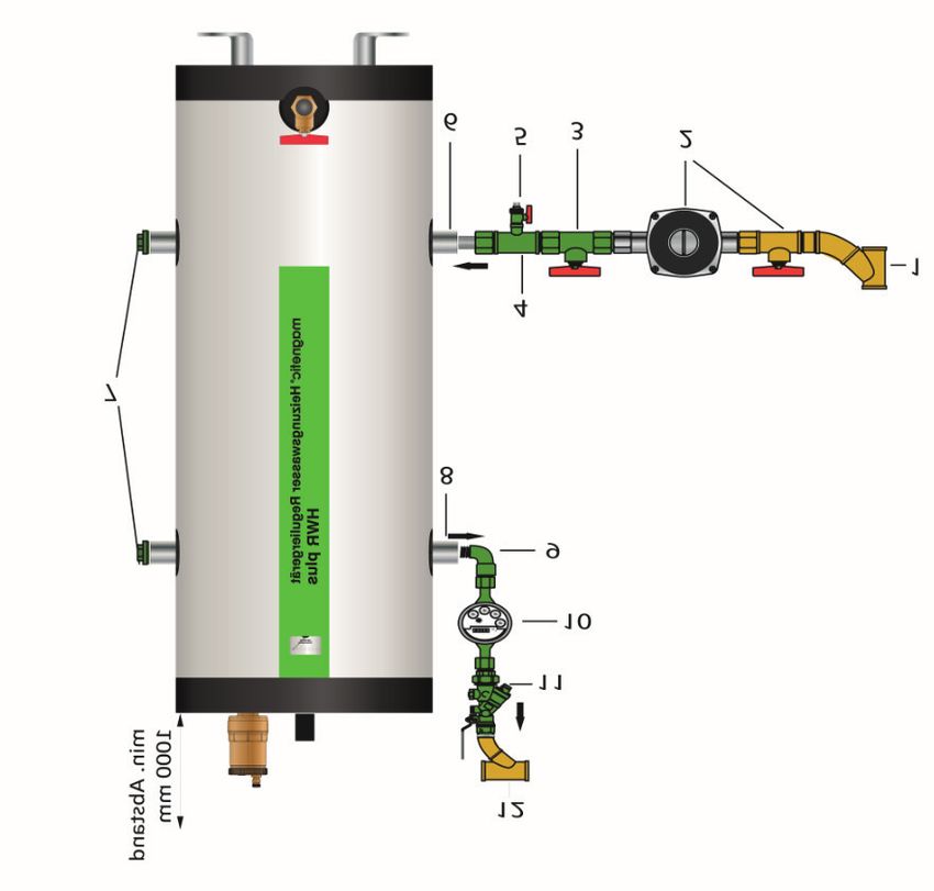
DE
magnetic
HWR 50/100 plus
Heizungswasser Reguliergerät
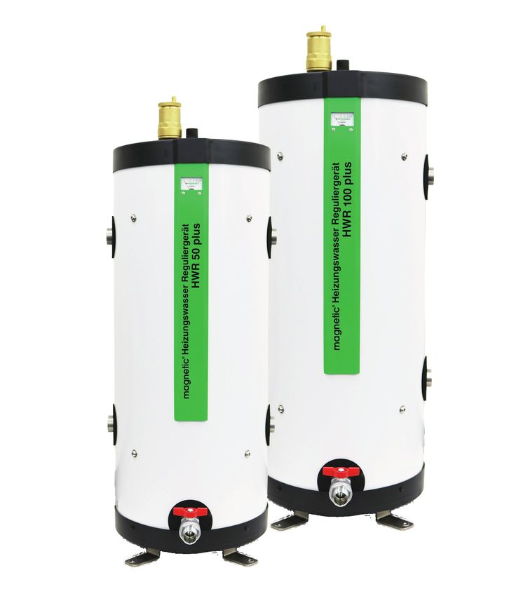
Beschreibung
Elektrochemisches Korrosionsschutzgerät zur pH-Wertstabilisierung nach VDI 2035 und Sauerstoffbin-
dung. Besteht aus rostfreiem Reaktionsbehälter mit Mikrogasblasenabscheider und integriertem Magnet-
flussfilter, sowie Abschlämmfunktion und austauschbaren Hochpotentialschutzanoden für den Einbau in
geschlossenen Heiz- und Kühlkreisläufe. Mit Funktionsanzeige und Überwachungseinrichtung der Hoch-
leistungsschutzanoden, geeignet für Heizungsanlagen bis zu 15.000 Liter (HWR 50 plus) bzw. 35.000 Liter
(HWR 100 plus) Heizleistung. Durch die Kombination von 3 Korrosionsschutzmaßnahmen in einem Gerät
eignet sich der HWR 50/100 plus optimal zur dauerhaften Regulierung des Heizungswassers.
Technische Daten
Typenbezeichnung HWR 50 plus HWR 100 plus
Anlagenvolumen* max. 15.000 l 35.000 l
Volumen geschätzt** ~ 18,5 l/kW FBH ~ 18,5 l/kW FBH
~ 12 l/kW Radiatoren ~ 12 l/kW Radiatoren
Montage Boden-Bypass Boden-Bypass
Max. Betriebstemperatur 90 °C 90 °C
Betriebsdruck 6 bar 6 bar
Prüfdruck 10 bar 10 bar
Reaktorbehälter Edelstahl V4A Edelstahl V4A
Verkleidung / Dämmung Alu-Dibond / HT/ARMAFLEX Alu-Dibond / HT/ARMAFLEX
* Ohne Berücksichtigung von Pufferspeicher.
** Bei alten Anlagen mit neuem Wärmeerzeuger ca. 20% auf die Heizleistung hinzurechnen.
Installationshinweis
• Das Gerät wird in einem Bypass eingebunden, die Zuleitung erfolgt über ein 1“ Rohr
• Der Durchfluss muss auf 10 Liter pro Minute eingeregelt werden
• Material bauseits: ggf. 1“ Zuführungspumpe mit Pumpenkugelhahn (z.B. Wilo Stratos PICO 25/1-4 in
Regelungsart Differenzdruck konstant)
magnetic GmbH & Co. KG | Am Richtbach 5 | D-74547 Untermünkheim
www.magnetic-online.de | info@magnetic-online.de
DE

magnetic
HWR 50/100 plus
Heizungswasser Reguliergerät

Maße

 Maße                                        HWR 50 plus              HWR 100 plus

 A      Durchmesser                          370 mm                   370 mm

 B      Breite inkl. Anschlussrohre          403,5 mm                 403,5 mm

 C      Höhe gesamt                          1060 mm                  1210 mm

 D      Boden – Mitte Zulauf                 295,5 mm                 295,5 mm

 E      Boden – Mitte Auslauf                745,5 mm                 895,5 mm

 F      Tiefe inkl. Kugelhahn                460 mm                   460 mm

 G      Mindestabstand                       1000 mm                  1000 mm

 Zulauf - unten / Auslauf oben               1“                       1“

Installationsprinzip mit Anschlussset
Im Lieferumfang enthaltenes Zubehör:
• Wasserzähler mit Anschlussverschraubungen
• Anschluss-Set - komplette Anschlussarmatur mit allen für den Betrieb notwendigen Armaturen

 Im gelieferten Anschluss-Set enthalten:

 (3)       Kugelhahn 1“

 (4)       T-Stück 1“ x 1“ x 1/2“

 (5)       KFE-Hahn 1/2“

 (6)       Doppelnippel 1“

 (7)       Blindstopfen 1“

 (8)       Reduzierung 1“ x 3/4“

 (9)       Winkelstück     3/4“

 (10)      Wasserzähler (drehbar) 3/4“, mit Verschraubung

 (11)      Regulierventil mit automatischer Durchflussregelung

 Bauseits zu stellen:

 (1)       Einschweißschuh oder T-Stück für 1“ Zuleitung An-schluss ggf. 1

           Zuführpumpe mit Pumpenkugelhahn, nicht drehzahlgeregelt (z.B.
 (2)       Wilo Stratos PICO 25/1-4 in Regelungsart Differenzdruck konstant),
           mit Heizungs-umwälzpumpe gleichgeschaltet

 (12)      Einschweißschuh oder T-Stück für 3/4“ Auslauf-Anschluss

                        magnetic GmbH & Co. KG | Am Richtbach 5 | D-74547 Untermünkheim
                                      www.magnetic-online.de | info@magnetic-online.de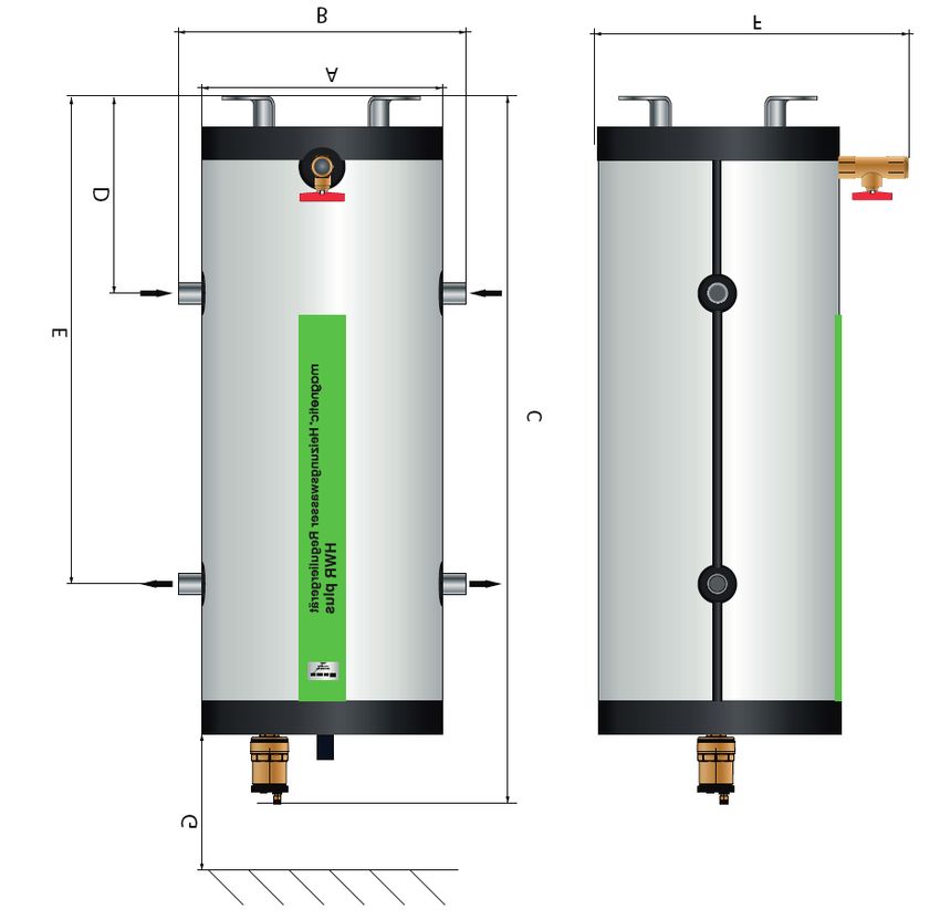
ENG

magnetic
HWR 50/100 plus
Heating water regulator

Description
Electrochemical corrosion protection device consisting of a corrosion-resistant reaction vessel with micro
bubble remover and integrated magnetic flux filter with sludge removal function and a replaceable high-
potential protective anode with Mg-Mn special alloy. For the permanent installation in closed circuit hea-
ting/cooling systems in accordance with VDI 2035. With function meter and monitoring device for the high-
performance protective anode. suitable for heating systems up to 15,000 liters (HWR 50 plus) or 35,000
liters (HWR 100 plus) heating capacity. Due to the combination of 3 proven corrosion protection methods
in one device, the HWR 50/100 plus is optimally suited for the permanent regulation of the heating water.

Technical Data

    Type                              HWR 50 plus                          HWR 100 plus

    System volume* max.               15000 l                              35000 l

    Estimated volume**                ~ 18,5 l/kW Floor heating            ~ 18,5 l/kW Floor heating
                                      ~ 12 l/kW Radiators                  ~ 12 l/kW Radiators

    Installation                      Floor-Bypass                         Floor-Bypass

    Operating temperature max.        90 °C                                90 °C

    Operating pressure                6 bar                                6 bar

    Testing pressure                  10 bar                               10 bar

    Reactor vessel                    Chrome steel V4A                     Chrome steel V4A

    Casing / Insulation               Alu-Dibond / HT/ARMAFLEX             Alu-Dibond / HT/ARMAFLEX

*          Without taking into account a buffer tank
**         About 20% must be added to the capacity in the case of old system with a new heat source

Installationshinweis
•     The device must be connected in a bypass, the supply is effected via 1” pipe
•     The flow rate must be set to 10 litres per minute
•     Material tob e provided by the customer: if required, a 1“ supply line pump with ball valve. (e.g. Wilo
      Stratos PICO 25/1-4 in ‘constant differential pressure’‘ control mode)

                   magnetic GmbH & Co. KG | Am Richtbach 5 | D-74547 Untermünkheim
                             www.magnetic-online.de | info@magnetic-online.de
ENG
magnetic
HWR 50/100 plus
Heating water regulator
Dimensions
Dimensions HWR 50 plus HWR 100 plus
A Diameter 370 mm 370 mm
B Width incl. connecting pipes 403,5 mm 403,5 mm
C Total height 1060 mm 1210 mm
D Bottom – inlet centre 295,5 mm 295,5 mm
E Bottom – outlet centre 745,5 mm 895,5 mm
F Depth incl. ball valve 460 mm 460 mm
G Min. clearance 1000 mm 1000 mm
inlet, bottom / outlet, top 1“ 1“
Installations principle with installation kit
Accessories included in the scope of supply:
• Water quantity counter with screw coupling
• Installation kit - complete installation kit with all valves and fittings necessary for operation.
Included in the supplied installation kit:
(3) Ball valve 1“
(4) T-fitting 1“ x 1“ x 1/2“
(5) Fill & Drain valve 1/2“
(6) Full coupling 1“
(7) Plug 1“
(8) Reducer 1“ x 3/4“
(9) Elbow 3/4“
(10) Water quantity counter (rotatable) 3/4" with screw coupling
(11) Regulating valve with automatic flow regulation
To be supplied by customer:
(1) Buttweld coupling or T-fitting for 1“ supply line con-nection
(2) Supply line pump with pump ball valve, not speed-regulated, swit-
ched together with water circulating pump
(12) Buttweld coupling or T-fitting for 3/4"“ outlet coneection
magnetic GmbH & Co. KG | Am Richtbach 5 | D-74547 Untermünkheim
www.magnetic-online.de | info@magnetic-online.deFR
magnetic
HWR 50/100 plus
Régulateur d‘eau de chauffage
Description
Dispositif électrochimique de protection contre la corrosion composé d‘une cuve de réacteur en acier
inoxydable avec séparateur de microbulles de gaz et filtre à flux magnétique intégrés, avec fonction de dé-
colmatage et anode sacrificielle haute performance remplaçable en alliage spécial Mg-Mn à installer. Avec
dispositif d‘affichage et de contrôle des fonctions de l‘anode de protection haute performance. Convient
aux systèmes de chauffage jusqu‘à 15 000 litres (HWR 50 plus) ou 35 000 litres (HWR 100 plus). La com-
binaison de trois types de protection éprouvés en un seul appareil assure une régulation permanente de
l‘eau de chauffage.
Fiche technique
Type HWR 50 plus HWR 100 plus
Volume de l’installation* max. 15000 l 35000 l
Volume estimé** ~ 18,5 l/kW Chauffage au sol ~ 18,5 l/kW Chauffage au sol
~ 12 l/kW Radiateurs ~ 12 l/kW Radiateurs
Montage Sol-Bypass Sol-Bypass
Température d‘utilisation max. 90 °C 90 °C
Pression de service 6 bar 6 bar
Pression de contrôle 10 bar 10 bar
Cuve de réacteur Acier chromé V4A Acier chromé V4A
Carénage / Isolation Alu-Dibond / HT/ARMAFLEX Alu-Dibond / HT/ARMAFLEX
* Sans tenir compte du ballon.
** Pour les vieilles installations équipées d’un générateur de chaleur neuf, ajouter env. 20% à la puissance
de chauffe.
Instructions de montage
• L’appareil est relié par un bypass, l’alimentation se fait par un tuyau de 1“
• Le débit doit être réglé sur 10 litres/minute
• Matériau sur site: éventuellement pompe d’alimentation 1“ avec vanne à sphère (ex. Wilo Stratos PICO
25/1-4 avec mode de régulation par pression différentielle constante)
magnetic GmbH & Co. KG | Am Richtbach 5 | D-74547 Untermünkheim
www.magnetic-online.de | info@magnetic-online.deFR
magnetic
HWR 50/100 plus
Régulateur d‘eau de chauffage
Dimensions
Dimensions HWR 50 plus HWR 100 plus
A Diamètre 370 mm 370 mm
B Largeur avec tuyaux de raccor-
403,5 mm 403,5 mm
dement
C Hauteur totale 1060 mm 1210 mm
D Fond – centre entrée 295,5 mm 295,5 mm
E Fond – centre sortie 745,5 mm 895,5 mm
F Arrière – centre raccordement 460 mm 460 mm
G Largeur avec vanne à sphère 1000 mm 1000 mm
inlet, bottom / outlet, top 1“ 1“
Principe d’installation avec kit de raccordement
Accessoires compris dans la livraison:
• Compteur de quantité d‘eau avec raccord à vis
• Kit d‘installation - kit d‘installation complet avec toutes les vannes et tous les raccords nécessaires au
fonctionnement.
Le kit de raccordement fourni comprend:
(3) Vanne à sphère 1“
(4) Pièce en T 1“ x 1“ x 1/2“
(5) Robinet KFE 1/2“
(6) Raccord double 1“
(7) Obturateur 1“
(8) Réduction 1“ x 3/4“
(9) Coude 3/4“
(10) Compteur d‘eau (rotatif) 3/4“ avec rac-cord vissé
(11) Vanne de régulation avec régulation automatique de débit
Mettre à disposition sur le site:
(1) Sabot soudé ou pièce en T 1“, éventuel-lement raccord d’alimen-
tation 1“
Pompe d’alimentation avec vanne à sphère, sans régulation de
(2) vitesse (ex. Wilo Stratos PICO 25/1-4 à régulation par pression
différentielle constante), avec circulateur de chauffage simultané
(12) (12) Sabot soudé ou pièce en T pour raccord de sortie 3/4“
magnetic GmbH & Co. KG | Am Richtbach 5 | D-74547 Untermünkheim
www.magnetic-online.de | info@magnetic-online.deIT
magnetic
HWR 50/100 plus
Regolatore dell‘acqua di riscaldamento
Descizione
Dispositivo elettrochimico di protezione dalla corrosione, composto da un recipiente di reazione in acciaio
inossidabile, dotato di un separatore di microbolle di gas e di un filtro magnetico integrato, nonché di una
funzione di pulizia e di un anodo protettivo ad alte prestazioni sostituibile, per l‘installazione fissa in circuiti
chiusi di riscaldamento e raffreddamento secondo VDI 2035. Con display di funzionamento e dispositivo di
monitoraggio anodico ad alta efficienza, adatto a sistemi di riscaldamento fino a 15000 litri (HWR 50 plus)
o 35000 litri (HWR 100 plus). Grazie alla combinazione di 3 misure di protezione contro la corrosione in un
solo apparecchio, l‘HWR 50/100 plus è perfettamente adatto alla regolazione permanente dell‘acqua di
riscaldamento.
Data tecnici
Tipo HWR 50 plus HWR 100 plus
Volumi max. dell’impianto* 15000 l 35000 l
Volumi stimati** ~ 18,5 l/kW risc. a pav. ~ 18,5 l/kW risc. a pav.
~ 12 l/kW Radiatori ~ 12 l/kW Radiatori
Montaggio Pavimento-Bypass Pavimento-Bypass
Temperatura in esercizio 90 °C 90 °C
Pressione di esercizio 6 bar 6 bar
Pressione di prova 10 bar 10 bar
Contenitore dove avviene la
reazione Acciaio cromato V4A Acciaio cromato V4A
Rivestimento / isolamento Alu-Dibond / HT/ARMAFLEX Alu-Dibond / HT/ARMAFLEX
* Senza considerare il serbatoio di accumulo.
** In caso di impianti vecchi con caldaia nuova aggiungere ca. 20% al rendimento del riscaldamento.
Istruzioni per l’installazione
• Inserire l’apparecchio in un bypass collegandolo tramite un tubo da 1”
• Impostare la portata a 10 litri al minuto
• Nel punto di installazione prevedere event. una pompa di convogliamento da 1” con rubinetto (ad es.
Wilo Stratos PICO 25/1-4 in tipo di regolazione pressione differenziale costante)
magnetic GmbH & Co. KG | Am Richtbach 5 | D-74547 Untermünkheim
www.magnetic-online.de | info@magnetic-online.deIT
magnetic
HWR 50/100 plus
Regolatore dell‘acqua di riscaldamento
Dimensioni
Dimensioni HWR 50 plus HWR 100 plus
A Diametro 370 mm 370 mm
B Largh. incl. tubi di collegamento 403,5 mm 403,5 mm
C Altezza complessiva 1060 mm 1210 mm
D Afflusso pavimento-centro 295,5 mm 295,5 mm
E Deflusso pavimento-centro 745,5 mm 895,5 mm
F Collegamento retro-centro 460 mm 460 mm
G Largh. incl. rubinetto 1000 mm 1000 mm
Afflusso - lato inf. / Deflusso - lato sup. 1“ 1“
Principio di installazione con il kit di collegamento
Accessori inclusi nella fornitura:
• Contatore di quantità d‘acqua con attacco a vite
• Kit di installazione - kit di installazione completo con tutte le valvole e i raccordi necessari per il funzio-
namento.
Il kit di collegamento comprende:
(3) Rubinetto a sfera 1”
(4) Raccordo a T 1” x 1” x ½”
(5) Rubinetto a sfera di riempimento e svuo-tamento ½”
(6) Nipplo doppio 1”
(7) Tappo cieco 1”
(8) Riduzione 1” x ¾”
(9) Raccordo ad angolo ¾”
(10) Contatore (girevole) ¾” con raccordo
(11) Valvola di regolazione con regolazione automatica della portata
Nel punto di installazione prevedere:
(1) Piastra di saldatura o raccordo a T per collegamento afflusso da 1”
Pompa con rubinetto, senza regolazione del numero di giri (ad es. Wilo Stratos
(2) PICO 25/1-4 in tipo di regolazione pressione differenziale costante), sincronizzata
con la pompa di circolazione nella rete di riscaldamento
(12) (12) Piastra di saldatura o raccordo a T per collegamento deflusso da ¾”
magnetic GmbH & Co. KG | Am Richtbach 5 | D-74547 Untermünkheim
www.magnetic-online.de | info@magnetic-online.deVous pouvez aussi lire