Operation Manual - Lancer Worldwide
←
→
Transcription du contenu de la page
Si votre navigateur ne rend pas la page correctement, lisez s'il vous plaît le contenu de la page ci-dessous
IBD Bold 30i

                                         Operation Manual

                                                                              Model TP30

“Lancer” and “Lancer Worldwide” are registered trademarks of Lancer Corp.
© 2021 by Lancer, all rights reserved.

         For more Information visit lancerworldwide.com or call Tech Support/Warranty: 800-729-1550
6655 Lancer Boulevard • San Antonio, TX 78219 • custserv@lancerworldwide.com • ©2021 Lancer Worldwide • Lancer PN: 28-3111 • Revision 2/15/2022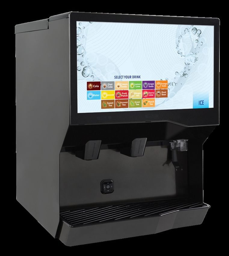
TABLE OF CONTENTS
ABOUT THIS MANUAL                                                                   BEFORE GETTING STARTED
This booklet is an integral and essential part of the product                       Each unit is tested under operating conditions and is
and should be handed over to the operator after the                                 thoroughly inspected before shipment. At the time of
installation to keep as a reference. Please read carefully the                      shipment, the carrier accepts responsibility for the unit.
guidelines and warnings contained herein as they are intended                       Upon receiving the unit, carefully inspect the carton for visible
to provide the user with essential information for the continued                    damage. If damage exists, have the carrier note the damage
safe use and maintenance of the product. In addition, it                            on the freight bill and file a claim with carrier. Responsibility
provides GUIDANCE ONLY to the user on the correct services                          for damage to the dispenser lies with the carrier.
and site location of the unit.

The installation or relocation of this product must be carried out by qualified personnel with
up-to-date safety and hygiene knowledge and practical experience, in accordance with current regulations.

IMPORTANT SAFETY INSTRUCTIONS...................... 3-5                                Customize............................................................ 22-24
   Intended Use............................................................... 3       Digital Merchandising................................................24
   Electrical Warning....................................................... 3         Load USB...................................................................25
   CO2 Warning............................................................... 4        Import USB Data....................................................... 26
   CO2 Safe Handling and Storage................................. 4                    Export USB Data.......................................................27
   Water Notice............................................................... 5       Maintenance..............................................................28
   Automatic Agitation.................................................... 5           Lancer Link Setup..................................................... 29
SPECIFICATIONS AND FEATURES............................ 6-7                            Settings................................................................30-31
   IBD Bold 30i................................................................ 6   CLEANING AND SANITIZING.................................. 32-34
   General Systems Overview-Remote Syrup Pumps... 7                                    General Information.................................................. 32
                                                                                       Cleaning and Sanitizing Solutions............................ 33
PRE-INSTALLATION CHECKLIST..................................7
                                                                                       Scheduled Maintenance/Cleaning........................... 33
INSTALLATION............................................................ 8-16          Cleaning and Sanitizing Nozzles.............................. 34
   Unpacking the Dispenser........................................... 8                Cleaning Syrup Lines - Bag in Box.......................... 34
   Selecting/Preparing a Counter Location.................... 9
                                                                                    TROUBLESHOOTING...............................................35-38
   Installing an Icemaker................................................10
   Dispenser Installation........................................... 11-12          ILLUSTRATIONS AND PART LISTINGS.................39-47
   Condensation Fan Installation...................................13                  Graphics & Labels Assembly................................... 39
   Installing Remote Syrup Pumps-Bag in Box............14                              Main Unit Assembly............................................. 40-41
   Installing CO2 Supply.................................................15            Electrical Assembly................................................... 42
   Dispenser Setup........................................................16           Display Assembly ..................................................... 43
   Access Service Menu................................................16               SBC Wiring Diagram ................................................ 43
IBD BOLD 30i SERVICE MENU................................17-31                         Plumbing Diagram.................................................... 44
   Water Purging............................................................17         Valve Wiring Diagram................................................ 44
   Adding Brand/Flavor Valves......................................18                  Power Supply Wiring Diagram................................. 45
   Plain/Carb Water Calibration.....................................19                 Unit Wiring Diagram.................................................. 46
   Graduated Cylinder Syrup Calibration..................... 20                        DIP Switch Legend................................................... 46
   Ratio Cup Syrup Calibration......................................21                 Counter Cutout..........................................................47
   Sold Outs.................................................................. 22

  2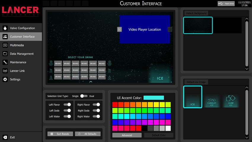
IMPORTANT SAFETY INSTRUCTIONS
READ ALL SAFETY INSTRUCTIONS BEFORE USING THIS UNIT.
This manual contains important safety information and all applicable safety precautions must be observed. To reduce
the risk of fire, electric shock, damage to the equipment or personal injury when using this unit all instuctions/warnings
on the product being used must be followed:

  ! WARNING                                                                  ! ATTENTION
 Text following the Warning signal indicates a                              Text following the Attention signal addresses a
 hazardous situation, which if not avoided, will result                     situation that if not followed could potentially
 in death or serious injury. Be sure to read all Warning                    damage the equipment. Be sure to read the Attention
 statements before proceeding with the installation.                        statements before proceeding.

 ! CAUTION                                                                    NOTE
 Text following the Caution signal indicates a                              Text following the Note signal provides you with
 hazardous situation, which if not avoided, could                           information that may help you more effectively perform
 result in minor or moderate injury. Be sure to read                        the installation procedures within this manual.
 the Caution statements before proceeding with the                          Disregarding information will not cause damage or
 installation.                                                              injury, however it may limit the performance of the
                                                                            dispenser.

   ! Intended Use
 The dispenser is for indoor use only. This unit is not a toy. Children should be supervised not to play with appliance. It should not
 be used by children or infirm persons without supervision. This appliance can be used by children aged from 8 years and above
 and persons with reduced physical, sensory or mental capabilities or lack of experience and knowledge if they have been given
 supervision or instruction concerning use of the appliance in a safe way and understand the hazards involved. Cleaning and user
 maintenance shall not be performed by children without supervision. The min/max ambient operating temperature for the dispenser
 is 40°F to 105°F (4°C to 41°C) at a max altitude of 16,400 ft (5,000 m). Do not operate unit outside these conditions. Should
 freezing occur, cease operation of the unit and contact authorized service technician. Service, cleaning, and sanitizing should be
 accomplished only by trained personnel. During installation, old hose-sets should not be reused to connect the unit to the water
 mains; new hose-sets should always be used. Applicable safety precautions must be observed. Instruction warnings on the product
 being used must be followed.

   ! Utilisation prévue
 La distributrice doit être utilisée à l’intérieur uniquement. Cet appareil n’est pas un jouet. Ne laissez pas les enfants jouer avec l’appareil.
 Cet appareil ne doit pas être utilisé par des enfants ou des personnes handicapées sans supervision. Cet appareil peut être utilisé par
 des enfants âgés de 8 ans et plus et des personnes ayant des capacités physiques, sensorielles ou mentales réduites ou un manque
 d’expérience et de connaissances s’ils ont reçu une supervision ou des instructions concernant l’utilisation de l’appareil en toute
 sécurité et comprennent les risques impliqué. Le nettoyage et l’entretien journalier ne doivent pas être effectués par des enfants sans
 supervision. La température ambiante de fonctionnement de la distributrice se situe entre 40 °F et 105 °F (4 °C et 41 °C) à une altitude
 maximale de 16 400 pied (5 000 mètre). Ne faites pas fonctionner l’appareil en dehors de ces conditions. Si l’appareil a gelé, cessez de
 l’utiliser et contactez un technicien d’entretien autorisé. Le personnel assigné au nettoyage, à la désinfection et à l’entretien de l’appareil
 doit avoir reçu une formation à cet effet. Lors de l'installation, les ensembles de raccordement de tuyaux usagé ne doivent pas être
 réutilisés pour être raccordés l'unité au réseau d'alimentation en eau; de nouveaux ensembles de tuyaux doivent toujours être utilisés.
 Les mesures de sécurité en vigueur doivent être suivies. Observez toutes les étiquettes de sécurité apposées sur l’appareil.

   F Electrical Warning
 Check the dispenser nameplate label, located behind the splash plate, for the correct electrical requirements of unit. Do not plug
 into a wall electrical outlet unless the current shown on the serial number plate agrees with local current available. Follow all local
 electrical codes when making connections. Each dispenser must have a separate electrical circuit. Do not use extension cords
 with this unit. Do not ‘gang’ together with other electrical devices on the same outlet. Do not locate multiple portable socket-
 outlets or portable power supplies at the rear of the appliance. The key-switch does not disable the line voltage to the transformer
 primary. Always disconnect electrical power to the unit to prevent personal injury before attempting any internal maintenance.
 The resettable breaker switch should not be used as a substitute for unplugging the dispenser from the power source to service
 the unit. Only qualified personnel should service internal components of electrical control housing. Make sure that all water lines
 are tight and units are dry before making any electrical connections!

                                                                                                                                               3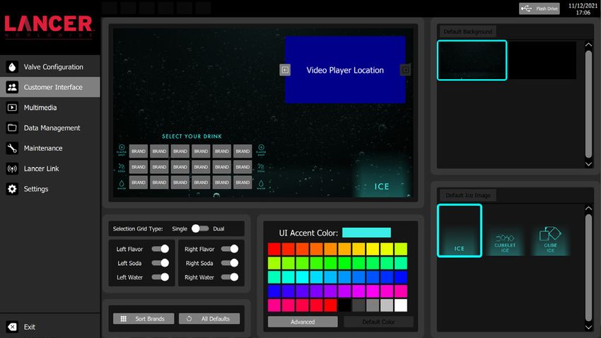
F Avertissement - Électricité
Reportez-vous à l’étiquette d’identification de la distributrice située derrière la plaque antiéclaboussures pour connaître les
caractéristiques électriques de l’appareil. Ne branchez pas l’appareil dans une prise électrique murale à moins que le courant
disponible corresponde à l’intensité nominale indiquée sur l’étiquette portant le numéro de série. Les raccordements électriques
doivent être conformes au code électrique local. Chaque distributrice doit être branchée dans un circuit électrique dédié. Ne raccordez
pas cet appareil à l’aide d’une rallonge électrique. Ne branchez pas cet appareil dans une prise électrique multiple partagée par
d’autres appareils. Ne placez pas plusieurs prises d’alimentation multiples portables ou alimentations électriques portables à l’arrière
de l’appareil. L’interrupteur verrouillable ne désactive pas la tension de ligne au primaire du transformateur. Débranchez toujours
l’alimentation électrique de l’appareil avant une intervention d’entretien afin de prévenir des blessures. L’ouverture du disjoncteur
à réarmement ne remplace pas le débranchement de la distributrice au moment de procéder à une intervention d’entretien. Seul
le personnel qualifié est autorisé à faire l’entretien et la réparation des composants électriques logés dans le boîtier du module de
commande. Veillez à ce que les conduites d’eau soient étanches et que l’appareil soit sec avant de procéder à des raccordements
électriques.

    5 Carbon Dioxide (CO2)
•     WARNING: Carbon Dioxide (CO2) is a colorless, noncombustible gas with a light pungent odor. High percentages of CO2 may
      displace oxygen in the blood.
•     WARNING: Prolonged exposure to CO2 can be harmful. Personnel exposed to high concentrations of CO2 gas will experience
      tremors which are followed by a loss of consciousness and suffocation.
•     WARNING: If a CO2 gas leak is suspected, immediately ventilate the contaminated area before attempting to repair the leak.
•     WARNING: Strict attention must be observed in the prevention of CO2 gas leaks in the entire CO2 and soft drink system.

    5 Dioxyde de carbone (CO2)
•     AVERTISSEMENT : Le dioxyde de carbone (CO2) est un gaz incolore et non combustible qui a une odeur âcre. Un pourcentage élevé de
      CO2 réduit la quantité d’oxygène dans le sang.
•     AVERTISSEMENT : L’exposition prolongée au CO2 est dangereuse pour la santé. Le personnel exposé à un taux élevé de CO2 souffre
      de tremblements qui sont suivis par une perte de conscience et la suffocation.
•     AVERTISSEMENT : Si vous suspectez une fuite de CO2, aérez immédiatement la zone contaminée avant de procéder à la réparation de la
      fuite.
•     AVERTISSEMENT : Il est impératif de prévenir toute fuite de CO2 dans le système de distribution de CO2 et de breuvage.

    5 CO2 Safe Handling and Storage
CO2 cylinders should only be handled by trained personnel who are aware of the hazards associated with CO2 gas. CO2 cylinders
should be handled with care. Never drag or drop a CO2 cylinder. Never attempt to handle a leaking CO2 cylinder. The valve should
always be closed when handling a cylinder. If the cylinder is fitted with a valve cap, always verify the cap is secure before handling.
Always store CO2 cylinders in an upright position and in a well-ventilated area. Never store CO2 cylinders near anything that emits
high heat and keep out of direct sunlight. Enclosed areas in which CO2 is being stored should be equipped with a CO2 monitoring
system.

    5 Manipulation et stockage sûrs du CO2
Les bouteilles de dioxyde de carbone ne doivent être manipulées que par du personnel formé et conscient des dangers associés au gaz
carbonique. Les bouteilles de dioxyde de carbone doivent être manipulées avec précaution. Ne jamais faire glisser ou laisser tomber une
bouteille de dioxyde de carbone. N’essayez jamais de manipuler une bouteille de dioxyde de carbone qui fuit. La vanne doit toujours être
fermée lors de la manipulation d’une bouteille. Si la bouteille est équipée d’un bouchon de valve, vérifiez toujours que le bouchon est bien
fixé avant de manipuler la bouteille. Stockez toujours les bouteilles de dioxyde de carbone en position verticale et dans un endroit bien
aéré. Ne rangez jamais les bouteilles de dioxyde de carbone à proximité de tout ce qui dégage beaucoup de chaleur et gardez-les à l’abri
de la lumière directe du soleil. Les zones fermées dans lesquelles le dioxyde de carbone est stocké doivent être équipées d’un système
de surveillance du dioxyde de carbone.

4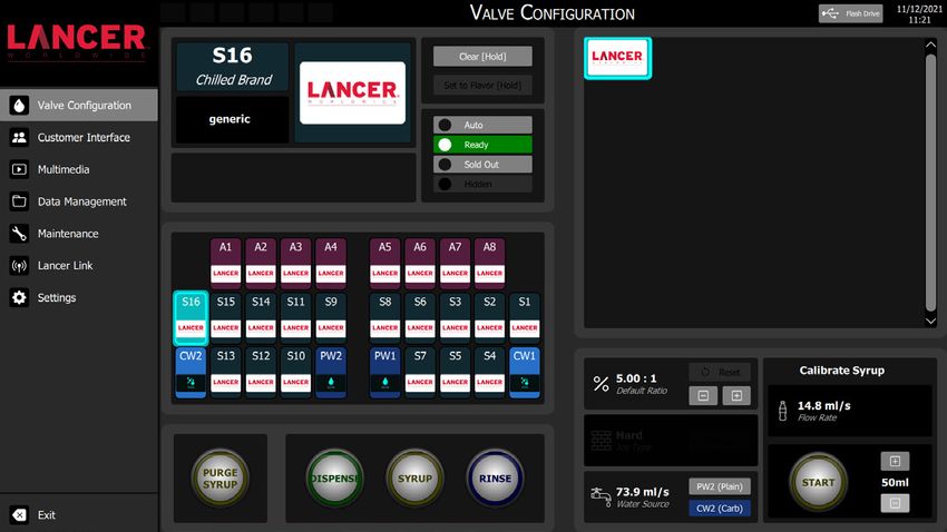
! Water Notice
Provide an adequate potable water supply. Water pipe connections and fixtures directly connected to a potable water supply
must be sized, installed, and maintained according to federal, state, and local laws. The water supply to the carbonator must be
at least a 3/8 inches (9.525 mm) pipe with a minimum of 75 psi (0.516 MPa) line pressure, but not exceeding a maximum of 125
psi (0.862 MPa). Water pressure exceeding 125 psi (0.862 MPa) must be reduced to 125 psi (0.862 MPa) with pressure regulator.
The water supply to non-carb drinks must be a minimum of 75 psi (0.517 MPa), using a water booster if needed. Use a filter in the
water line to avoid equipment damage and beverage off-taste. Check the water filter periodically, as required by local conditions.
The water supply must be protected by means of an air gap, a backflow prevention device or another approved method to comply
with NSF standards. A leaking inlet water check valve will allow carbonated water to flow back through the pump when it is shut
off and contaminate the water supply. Ensure the backflow prevention device complies with ASSE and local standards. It is the
responsibility of the installer to ensure compliance.

 ! Remarque relative à l’eau
Assurez-vous que l’alimentation en eau potable est suffisante. Les branchements et les raccords de tuyauterie d’eau directement reliés à
l’alimentation en eau potable doivent avoir la taille appropriée et être installés et entretenus conformément aux codes provincial et local.
La conduite d’alimentation en eau doit avoir un diamètre minimum de 3/8 po (9,525 mm) et une pression minimale de 75 psi (0,516 Mpa)
sans toutefois excéder 125 psi (0,862 Mpa). Si la pression d’eau excède 125 psi (0,862 Mpa), réglez le régulateur de pression à 125 psi
(0,862 Mpa). L’alimentation en eau des boissons sans carburateur doit être d’au moins 75 psi (0,517 MPa), en utilisant un surpresseur
d’eau si nécessaire. Installez un filtre dans la conduite d’eau pour protéger l’appareil et éliminer tout arrière-goût. Inspectez le filtre à eau
régulièrement, selon les conditions du réseau local. Le circuit d’alimentation en eau doit être protégé au moyen d’un clapet antiretour,
ou d’un dispositif antirefoulement ou d’une autre méthode conforme aux normes de la NSF. Dans le cas d’une fuite du clapet antiretour
de la conduite d’alimentation, l’eau gazéifiée refoule à travers la pompe (lorsqu’elle n’est pas en service) et contamine ainsi l’alimentation
en eau. Assurez-vous que le dispositif antirefoulement est conforme aux normes de l’ASSE et aux codes en vigueur localement. Cette
tâche est de la responsabilité de l’installateur.

 NOTE
    The dispenser should only be installed in a location where it can be overseen by trained personnel, and it should never be
    installed in an area where a waterjet can be used.

 REMARQUE
    Le distributeur de boissons ne doit être installé qu’à un endroit où il peut être surveillé par du personnel qualifié et ne doit
    jamais être installé dans une zone où un jet d’eau peut être utilisé.

! Automatic Agitation
•      Units are equipped with an automatic agitation system and will activate unexpectedly.
•      CAUTION: Do not place hands or foreign objects in the ice bin tank. Unplug the dispenser during servicing, cleaning, and
       sanitizing.
•      CAUTION: To avoid personal injury, do not attempt to lift the dispenser without assistance. For heavier dispensers, use a
       mechanical lift.

! Agitation Automatique
•      Les distributeurs de boissons sont équipés d’un système d’agitation automatique et s’activeront de manière inattendue.
•      MISE EN GARDE : Ne placez pas les mains ou des objets étrangers dans le réservoir de glace. Débranchez le distributeur
       de boissons pendant l’entretien, le nettoyage et l’assainissement.
•      MISE EN GARDE : Pour éviter des blessures corporelles, n’essayez pas de soulever le distributeur de boissons sans
       assistance. Pour les distributeurs de boissons plus lourds, utilisez un élévateur mécanique.

                                                                                                                                              5
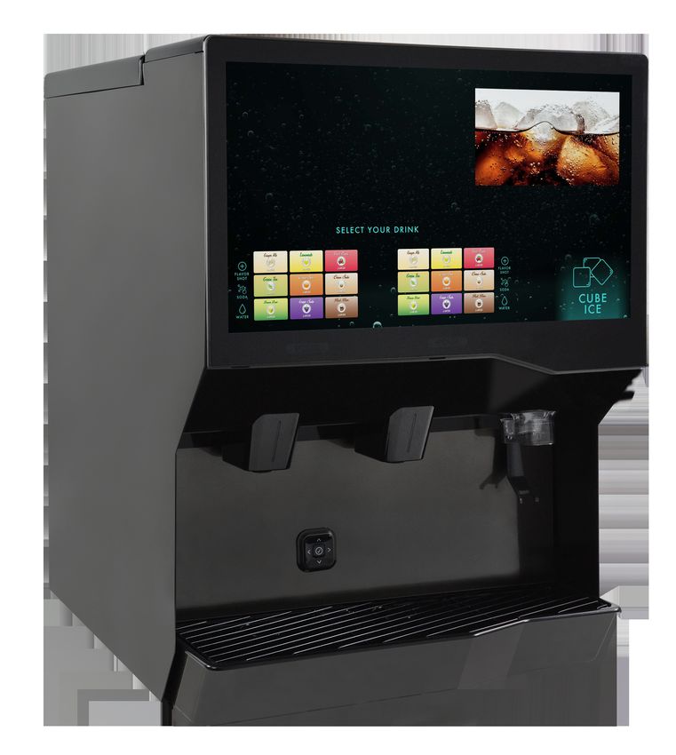
SPECIFICATIONS AND FEATURES
IBD BOLD 30i

                                                                                                            A

                          B

                      C

                                                                                                                40.60 in

                D

                                     30.00 in
                                                                                                   34.00 in
                                                                                                                   A. Top Cover
                                                                                                                   B. Touchscreen Display
                                                                                                                   C. Splash Plate
                                                                                                                   D. Cup Rest/Drip Tray

DIMENSIONS                                    ELECTRICAL                                     CARBON DIOXIDE (CO2) SUPPLY
     Width: 30.00 inches (762 mm)                 120 VAC / 60 Hz / 5.0 Amps                    Min Pressure: 70 psi (0.483 MPa)
     Depth: 34.00 inches (863.6 mm)                                                             Max Pressure: 80 psi (0.552 MPa)
                                                  220/240 VAC / 50/60 Hz / 2.5 Amps
     Height: 40.60 inches (1031.24 mm)
                                              CARBONATED WATER SUPPLY                        FITTINGS
WEIGHT                                                                                          Carbonator Inlet: 3/8 inch barb
                                                  Min Flowing Pressure: 25 psi (0.172 MPa)
     Shipping: 290 lbs (132 kg)                                                                 Plain Water Inlet: 3/8 inch barb
                                                  Max Static Pressure: 50 psi (0.345 MPa)
     Operating (w/ Ice): 570 lbs (259 kg)                                                       Brand Syrup Inlets: 3/8 inch barb
     Ice Capacity: 280 lbs (127 kg)                                                             Ambient Flavor Inlets: 3/8 inch barb
                                              PLAIN WATER SUPPLY                                CO2 Inlet: 3/8 inch barb
                                                  Min Flowing Pressure: 75 psi (0.517 MPa)

                                            This unit emits a sound pressure level below 70 dB
                                                      Max Altitude: 16,400 ft (5,000 m)

 6
General System Overview - Remote Syrup Pumps

                                                                                                                     Syrup Line
                                                                                          N
                                                                                                                     CO2 Line
                                                                                                                     Plain Water Line
                    J                                                              K
                                                                                                                     Carb Water Line
                                                                                                                     Drain Line
                                                 I                                                                   Electrical

                                                                                                     L
                                                                                                                   110

                                         E
   A                                                                                                 75   75

                D                                                                                                                 M
           B

                                                                                                               A. Water Source
                                                                                                               B. Water Booster
                                                                                                               C. Floor Drain
                                                                                                               D. Water Regulator
                                                                                                               E. Remote Pump
                        F   G    G   F       F       G    G    F          F   H    H      F                    F. Syrup Pump
                                                                                                               G. BIB Container
                        F            F       F                 F          F               F                    H. Ambient BIB
                            G    G                   G    G                   H    H
  C                                                                                                            I. Dispenser
                                                                                                               J. Icemaker (Opt)
                        F   G    G   F       F       G    G    F          F   H    H      F                    K. Electrical Outlet
                                                                                                               L. CO 2 Regulator
                        F   G    G   F       F       G    G    F          F   H    H      F                    M. CO2 Source
                                                                                                               N. Remote Tower

                                PRE-INSTALLATION CHECKLIST
TOOLS REQUIRED:                              POST MIX ACCESSORIES:                     CONSIDER THE FOLLOWING
                                                                                       BEFORE INSTALLATION:
       Oetiker Pliers                                High Pressure CO2 Regulator
                                                                                              Location of Water Supply Lines
       Tubing Cutters                                Low Pressure CO2 Regulator
                                                     Manifold                                 Location of Drain
       Wrench
                                                     CO2 Supply                               Location of Electrical Outlet
       Slotted Screwdriver
                                                     Chain for CO2 Tank                       Location of Heating and Air
       Phillips Screwdriver                                                                   Conditioning Ducts
                                                     Beverage Dispenser
       Drill                                                                                  Do you have enough space to
                                                     Beverage Tubing                          install the dispenser?
BIB SYSTEM:
                                                     Oetiker Clamp Fittings                   Is countertop level?
       BIB Rack
                                                     Water Booster (Lancer PN:                 an the countertop support
                                                                                              C
       BIB Syrup Boxes                               82-3401 or MC-163172                     the weight of the dispenser?
                                                                                              (Include the weight of an ice
       BIB Regulator Set                             Water Regulator                          machine plus weight of ice,
                                                                                              if necessary)
       BIB Connectors
                                                                                              Is dispenser located away from
                                                                                              direct sunlight or overhead
                                                                                              lighting?
                                                                                                                                        7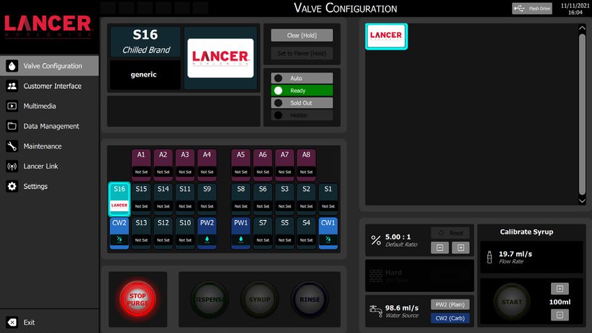
Read This Manual
This manual was developed by Lancer Worldwide as a reference guide for the owner/operator and installer
of this dispenser. Please read this manual before installation and operation of this dispenser. Please see
Troubleshooting section for service assistance. If the service cannot be corrected please call your Service
Agent or Lancer Customer Service. Always have your model and serial number available when you call.

                                                 INSTALLATION
Unpacking the Dispenser
1.   Set shipping carton upright on the floor then cut package   4.   Remove plywood shipping base from unit by moving unit so
     banding straps and remove.                                       that one side is off the countertop or table allowing access
2.   Open top of carton and remove interior packaging.                to screws on the bottom of the plywood shipping base.

3.   Lift carton up and off of the unit.                               NOTE
                                                                      If unit is to be transported, it is advisable to leave the
      NOTE                                                            unit secured to the plywood shipping base.
     Inspect unit for concealed damage. If evident, notify
     delivering carrier and file a claim against the same.
                                                                       REMARQUE
                                                                      Si l’appareil doit être transporté, il est conseillé de le
      REMARQUE                                                        laisser fixé sur la base d’expédition en contreplaqué.
     Inspectez l’appareil pour déceler des dommages cachés.
     Si l’appareil est endommagé, avisez le transporteur et      5.   Remove accessory kit and loose parts from ice
     soumettez-lui une réclamation.                                   compartment.
                                                                 6.   Clean ice chute and ice bin using cleaning solution on page
      ! WARNING                                                       33.

     Never energize the machine if there is any trace of         7.   If leg kit has been provided, assemble legs by tilting unit.
     damage. Contact Lancer Customer Service for
     assistance.                                                       ! ATTENTION
                                                                      DO NOT LAY UNIT ON ITS SIDE OR BACK.

      ! AVERTISSEMENT
     N’alimentez jamais la machine s’il y a une trace                  ! ATTENTION
     quelconque de dommage. Contactez le service à la
     clientèle de Lancer pour obtenir de l’aide.                      NEW COUCHEZ PAS L’APPAREIL SUR LE CÔTÉ OU
                                                                      SUR LE DOS.

                                                                       NOTE
                                                                      NSF listed units must be sealed to the counter or use
                                                                      legs provided.

                                                                       REMARQUE
                                                                      Les appareils homologués par la NSF doivent être scellés
                                                                      sur le comptoir ou reposer sur les pieds fournis.

 8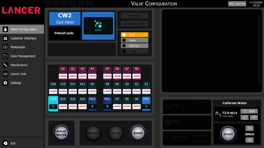
Selecting/Preparing a Counter Location
      NOTE                                                              Leveling the Dispenser
     The dispenser should only be installed in a location
                                                                       In order to facilitate proper dispenser drainage, ensure
     where it can be overseen by trained personnel, and it
                                                                       that the dispenser is level, front to back and side to
     should never be installed in an area where a waterjet
                                                                       side. Place a level on the top of the rear edge of the
     can be used.
                                                                       dispenser. The bubble must settle between the level
                                                                       lines. Repeat this procedure for the remaining three
      REMARQUE                                                         sides. Adjust as necessary. For optimum performance
     Le distributeur de boissons ne doit être installé qu’à un
                                                                       place the unit at a 0° tilt. The maximum tilt is 5°.
     endroit où il peut être surveillé par du personnel qualifié
     et ne doit jamais être installé dans une zone où un jet
     d’eau peut être utilisé.                                           Mise à niveau de la distributrice
                                                                       Afin de faciliter une vidange complète, assurez-vous
                                                                       que l’appareil est de niveau sur les axes avant arrière et
                                                                       gauche droit. Placez un niveau sur le bord arrière de la
1.   Select a levelled, well ventilated location that is in close
                                                                       distributrice. La bulle doit se situer entre les deux lignes.
     proximity to a properly grounded electrical outlet, within        Répétez la procédure sur les trois autres côtés. Ajustez
     five (5) feet (1.5 m) of a drain, a water supply that meets the   le niveau de l’appareil si nécessaire. Pour un résultat
     requirements shown in the Specifications section found on         maximal, réglez l’inclinaison à 0°. L’inclinaison maximale
     page 6, and away from direct sunlight or overhead lighting.       est de 5°.
2.   Sufficient clearance must be provided, if an ice maker is not
     installed, to allow filling ice compartment from a five gallon
     bucket (a minimum of 16 inches [40.6 cm] is recommended).          NOTE
3.   The selected location should be able to support the weight        To assure that beverage service is accessible to all
     of the dispenser, ice and possibly an icemaker being              customers, Lancer recommends that counter height
     installed after counter cut out is made. Total weight (with       and equipment selection be planned carefully. The
     icemaker) for this unit could exceed 800 pounds (363.6 kg).       2010 ADA Standards for Accessible Design states that
                                                                       the maximum reach height from the floor should be no
      NOTE                                                             more than 48” if touch point is less than 10” from the
     Lancer does NOT recommend the use of shaved or                    front of the counter, or a maximum of 46” if the touch
     flake ice in the dispenser.                                       point is more than 10” and less than 27” from the
                                                                       front of the counter. For more information about the
                                                                       customer’s legal requirements for the accessibility of
      REMARQUE                                                         installed equipment, refer to 2010 ADA Standards for
                                                                       Accessible Design - http://www.ada.gov.
     Lancer ne recommande pas l’utilisation de glace pilée
     ou en écailles dans le distributeur.
                                                                        REMARQUE
4.   Unit may be installed directly on countertop or on legs. If       Pour s’assurer que le service de boissons est accessible
     installed directly on the counter, unit must be sealed to the     à tous les clients, Lancer recommande que la hauteur du
                                                                       comptoir et la sélection de l’équipement soient planifiées
     countertop with an FDA approved sealant. If an icemaker is
                                                                       avec soin. Les normes 2010 de l’ADA pour la conception
     to be mounted on top of dispenser, do not install dispenser
                                                                       accessible stipulent que la hauteur de portée maximale
     on legs.
                                                                       depuis le sol ne doit pas dépasser 48” si le point de
      NOTE                                                             contact est à moins de 10 de l’avant du comptoir, ou un
                                                                       maximum de 46” si le point de contact est plus à moins
     NSF listed units must be sealed to the counter or use             de 10” et à moins de 27” de l’avant du comptoir. Pour
     legs provided.                                                    plus d’informations sur le les exigences légales du
                                                                       client concernant l’accessibilité de l’équipement installé,
                                                                       reportez-vous aux normes ADA 2010 pour la conception
      REMARQUE                                                         accessible - http://www.ada.gov.
     Les unités répertoriées NSF doivent être scellées au
     comptoir ou utiliser les pieds fournis.

5.   Select a location for the remote pump deck, syrup
     pumps, CO2 tank, syrup containers, and water filter
     (recommended). Please see General System Overview on
     page 7 for reference.
6.   Cut the necessary holes for the water, syrup, and CO2 lines
     in the designated countertop location for the dispenser.

                                                                                                                                 9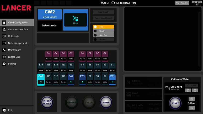
Installing an Icemaker (if necessary)

       ! ATTENTION                                                         Attach Bin Stat Bracket As Shown   Recommended Bin Stat Attachment
                                                                                                                    Bulb           Tube
      When installing an icemaker on the dispenser, use a
      bin thermostat to control the ice level (see below). This                              4”
      will prevent damage to the dispensing mechanism.
      The bracket for mounting a thermostat is located in
      the ice bin. During the automatic agitation cycle and
      while dispensing ice, ensure there is adequate space
      between the top of the ice level and the bottom of the
      icemaker so the ice can move without obstruction.
      Contact your icemaker manufacturer for information                     ! ATTENTION
      on a suitable bin thermostat.                                         Failure to use an ice bin thermostat will not only void
                                                                            your IBD’s warranty but will result in the inability to
                                                                            control the level of ice in the ice bin which can cause
       ! ATTENTION                                                          damage to your dispenser.
      Lorsque vous installez une machine à glaçons sur
      le distributeur, utilisez un thermostat de bac pour
      contrôler le niveau de glace (voir ci-dessous). Cela                   ! ATTENTION
      permettra d’éviter d’endommager le mécanisme                          Le fait de ne pas utiliser un thermostat de bac à glace
      de distribution. Le support pour le montage d’un                      annulera non seulement la garantie de votre IBD, mais
      thermostat est situé dans le bac à glace. Pendant le                  entraînera l’incapacité de contrôler le niveau de glace
      cycle d’agitation automatique et lors de la distribution              dans le bac à glace, ce qui peut endommager votre
      de la glace, assurez-vous qu’il y a suffisamment                      distributeur.
      d’espace entre le haut du niveau de glace et le bas
      de la machine à glaçons pour que la glace puisse se
      déplacer sans obstruction. Contactez le fabricant               5.    Ensure the icemaker is installed properly to allow for removal
      de votre machine à glaçons pour obtenir des                           of the merchandiser.
      informations sur un thermostat de bac adapté.                   6.    Ensure manual fill is accessible.
                                                                      7.    Clean and maintain icemaker per manufacturer’s
1.    Install the icemaker per manufacturer specifications. Points          instructions.
      of consideration include drainage, ventilation, and drop
      zones.
2.    An adapter plate is required when installing an icemaker.
      Contact your Sales Representative or Lancer Customer
      Service for more information.
3.    A bin thermostat is required in order to control the level of
      ice in the dispenser (Refer to ATTENTION note above).
      Contact your icemaker manufacturer to obtain the correct
      bin thermostat.
4.    Bin thermostat should be a minimum of 2” below the top
      edge of the dispenser. The preferred location of the bin
      thermostat is on the left side wall.

 10
Dispenser Installation
NOTE 3. Route appropriate tubing from the water source to the water
The installation or relocation must be carried out inlet at the remote pump deck.
by qualified personnel with up-to-date knowledge 4. Install water booster (Lancer PN MC-163172) between water
and practical experience in accordance with current supply and the remote pump deck.
regulations.
5. Using tubing cutters, cut the water supply line and install
U-fitting. Route appropriate tubing from the U-fitting to the
REMARQUE plain water inlet at the unit.
L’installation ou la réinstallation après un déplacement
doit être effectuée par un technicien qualifié C A. Line to Water Source
D
conformément aux codes en vigueur. B. U-Fitting
C. Line to Remote Pump Deck
D. Line to Plain Water Inlet
1. To access the valves behind the merchandiser for water
and syrup calibration (as shown under Service Menu A
section), the merchandiser must be lifted out of the way.
Grab the sides of the screen and pull out and up.
B
NOTE
Since this unit uses ice for cooling there is no risk of
water freezing within the tubes in the unit as long as
the unit is used indoors and not placed in extreme cold
A environments.
REMARQUE
Étant donné que ce distributeur de boissons utilise de
la glace pour le refroidissement, il n’y a aucun risque
de gel de l’eau à l’intérieur des tubes du distributeur de
B boissons tant qu’il est utilisé à l’intérieur uniquement et
non placé dans des environnements extrêmement froids.
A. Merchandiser 6. Route the appropriate tubing from the remote pump deck
B. Splash Plate outlet to the carbonated water inlet at the unit.
2. To remove splash plate, remove cup rest, then remove A. Remote Pump Deck
splash plate by pushing it up, bringing the bottom of it C B. Pump Inlet
forward and carefully pulling it out halfway to disconnect A C. Pump Outlet
the cable from the ADA kaypad. Once cable is D. Line to Carb Inlet
disconnected, pull out splash plate completely.
B
D
7. Install a shut-off valve in the water line feeding the remote
pump deck as well as the water line feeding the plain water
inlet.
118. Route appropriate tubing from the syrup pump location to
the syrup inlets and connect tubing to all syrup inlets. 11. Remove drip tray by lifting up and pulling out. Connect the
insulated drain line to the drain fitting.
C
C
A A. Oetiker Pliers
B. Tubing
C. Syrup/Water
B Inlet
A. Drain Fitting
NOTE A B. Drain Line
B C. Drip Tray
See Plumbing Diagrams on the front of the unit or on
page 44 for reference.
! CAUTION
REMARQUE Drain line must be insulated with a closed cell
insulation. Insulation must cover the entire length of
Voir les schémas de plomberie sur le devant de l’unité the drain hose, including fittings. The drain should be
ou à la page 44 pour référence. installed in such a manner that water does not collect
in sags or other low points, as condensation will form.
9. Route appropriate tubing from the CO2 source location to
the CO2 inlet on the unit and connect tubing to inlet.
! MISE EN GARDE
10. Route the power supply cord to a grounded electrical outlet
of the proper voltage and amperage rating. La conduite d’évacuation doit être isolée avec une
isolation à cellules fermées. L’isolation doit couvrir
toute la longueur du tuyau de vidange, y compris les
F WARNING raccords. Le drain doit être installé de manière à ce
DO NOT PLUG UNIT INTO GROUNDED ELECTRICAL que l’eau ne s’accumule pas dans les affaissements
OUTLET AT THIS TIME. Make sure that all water lines ou autres points bas, car de la condensation se
are tight and unit is dry before making any electrical formerait.
connections.
! ATTENTION
! AVERTISSEMENT Pouring hot water into drain may cause the drain
NE PAS BRANCHER L’APPAREIL DANS UNE PRISE tube to collapse. Allow only luke warm or cold water
ÉLECTRIQUE MISE À LA TERRE POUR LE MOMENT. to enter drain tube. Pouring coffee tea and similar
Assurez-vous que toutes les conduites d’eau sont substances into drain may cause the drain tube to
étanches et que l’unité est sèche avant d’effectuer des become clogged with coffee or tea grounds, or other
connexions électriques. solid particles.
! ATTENTION
Verser de l’eau chaude dans le drain peut provoquer
l’effondrement du tube de drainage. Ne laissez entrer
que de l’eau tiède ou froide dans le tube de vidange.
Le fait de verser du café, du thé et des substances
similaires dans le drain peut obstruer le tube de
drainage avec du marc de café ou de thé, ou d’autres
particules solides.
12Condensation Fan Installation
1. Install condensation fan on the underside of the unit by NOTE
(1) pushing fan bracket into slots in the right wall, then (2) When installing the drip tray, make sure both of the
sliding down to engage. cold plate drain hoses are lined up to the openings in
the drip tray. Make sure the end of the hose rests at
least a half of an inch over the edge of the opening to
ensure proper drainage of the cold plate.
REMARQUE
Lors de l’installation du bac d’égouttage, assurez-
2 vous que les deux tuyaux de vidange de la plaque
froide sont alignés avec les ouvertures du bac
d’égouttage. Assurez-vous que l’extrémité du tuyau
1 repose à au moins un demi-pouce sur le bord de
l’ouverture pour assurer un bon drainage de la plaque
froide.
2. Connect the unit’s red and black power harness to fan
connector.
3. Reattach drip tray and cup rest to the unit.
4. Reconnect the cable to the ADA keypad and reinstall the
splash plate.
13Installing Remote Syrup Pumps - Bag In Box
1. Install BIB rack and remote pumps according to 5. Install BIB (bag in box) connectors onto the syrup pump
manufacturers’ instructions. inlet tubing.
2. Once pumps and BIB rack are installed, measure and
cut tubing to length between the pump CO2 inlets, then ! ATTENTION
connect tubing to all pumps. Use proper connector for syrup manufacturer.
! ATTENTION
Utilisez le connecteur approprié spécifique au fabricant
de sirop.
A B C
A
C
B A. Syrup Pump
D B. CO2 Line
C. Fitting
D. Oetiker Pliers
3. Using tubing cutters, cut the CO2 supply line to the syrup
pumps and install tee fitting. Then, route the appropriate
tubing from the tee fitting to the syrup pumps and to the
A. Syrup Pump Inlet
unit. D B. Fitting
A. Tee Fitting C. BIB Connector
D B. CO2 Supply Line D. Oetiker Pliers
C. Line to Unit
D. Line to Syrup Pump 6. Connect syrup BIBs to connectors. Repeat for each syrup
B line/pump.
C
A
4. Connect tubing from dispenser syrup inlet to the syrup
pump outlet fitting. Repeat for each syrup line/pump.
C
A. Syrup Pump Inlet
A B B. BIB Connector
C. B
IB Syrup Container
B
C
A. Syrup Pump Outlet
B. Syrup Pump
A C. Fitting
14Installing CO2 Supply
1. Connect high pressure CO2 regulator assembly to CO2 3. Route appropriate tubing from the low pressure CO2
cylinder or bulk system. regulator manifold location to the 1/4” nut, 3/8” stem on
the high pressure CO2 regulator attached to source and
! ATTENTION connect tubing.
Before installing regulator, ensure that a seal (washer A A. CO2 Regulator
or O-ring) is present in regulator attachment nut. B. Fitting
C. L
ine to CO2 Regulator
Manifold
! ATTENTION D. Oetiker Pliers
Avant d’installer le régulateur, assurez-vous qu’un
joint torique ou une rondelle est en place dans l’écrou
d’accouplement du régulateur. B
C
D
A
C 4. Connect tubing routed from the CO2 inlet at the unit to one
of the low pressure CO2 regulator manifold outlets.
5. Connect tubing routed from the syrup pump location to the
second outlet of the low pressure CO2 regulator manifold.
A. Line to Dispenser
D B. Line to Syrup Pumps
C. Line to CO2 Regulator
D. CO2 Regulator Manifold
B
A. CO2 Regulator
- Thread regulator nut onto to tank, B. Outlet
then tighten nut with wrench C. Wrench C
D. CO2 Supply
D B
2. Connect a 1/4” nut, 3/8” stem and seal to CO2 regulator
A
outlet.
A 6. Using a wrench, loosen lock nut on the regulator
adjustment screw of the high pressure CO2 regulator
connected to the source, then using a screwdriver back out
lock nut screw all the way.
B
D ! WARNING
A. CO2 Regulator DO NOT TURN ON CO2 SUPPLY AT THIS TIME.
C B. Wrench
C. 1/4” nut, 3/8 stem ! AVERTISSEMENT
D. CO2 Supply
N’OUVREZ PAS L’APPROVISIONNEMENT EN
CO2 MAINTENANT.
! ATTENTION A. CO2 Regulator
A dedicated CO2 regulator is required to supply the A B. Screwdriver
CO2 inlet at the unit as well as to all remote syrup C. Loosened Lock Nut
pumps. D. Regulator Adjustment Screw
B
! ATTENTION
Un régulateur de CO2 spécifique est obligatoire pour
alimenter l’arrivée de CO2 à l’appareil ainsi que toutes
les pompes à sirop à distance. C D
7. Repeat Step 6 for both low pressure CO2 regulators on the
regulator manifold routed to the unit and the syrup pumps.
15Dispenser Setup
1. Turn on water source.
! AVERTISSEMENT
2. Open the pressure relief valve located on the front of the
unit by flipping up the valve cap lever. Hold open until water N’alimentez jamais la machine s’il y a une trace quel
flows from the relief valve; then, close (flip down) the relief conque de dommage. Contactez le service à la clientèle
valve. de Lancer pour obtenir de l’aide. Assurez-vous que
la distributrice est reliée à la terre pour éviter des
blessures graves ou des décharges électriques. Le
cordon d’alimentation comporte une fiche de terre à trois
broches. Si une prise électrique à trois trous n’est pas
disponible, utilisez une méthode approuvée pour assurer
la mise à la terre de l’appareil. Les raccordements
électriques doivent être conformes au code électrique
local. Chaque distributrice doit être branchée dans
un circuit électrique dédié. N’utilisez pas de rallonge
électrique. Ne branchez pas plusieurs appareils sur la
même prise de courant.
6. Turn on the power to the dispenser by pressing the circuit
breaker on the right side of the unit’s electrical box and
turning the 3-way key switch (located on the right side of the
unit) to the vertical position.
3. Verify all Bag-In-Box contains syrup and check all
connections for leaks.
4. Place enough ice in the ice bin to fill approximately 1/2 of
the bin before connecting the unit.
5. Connect unit power cord to grounded electrical outlet.
F WARNING A
Never energize the machine if there is any trace
of damage. Contact Lancer Customer Service
for assistance. The dispenser must be properly
electrically grounded to avoid serious injury or fatal A. Circuit breaker
electrical shock. The power cord has a three-prong
grounded plug. If a three-hole grounded electrical
outlet is not available, use an approved method to 7. Test the ice dispense feature by ensuring that the ice auger
ground the unit. Follow all local electrical codes when runs when the ice lever is pressed.
making connections. Each dispenser must have a
8. If necessary, turn on the screen by pressing the circuit
separate electrical circuit. Do not use extension cords.
breaker on the unit’s electrical box.
Do not connect multiple electrical devices on the
same outlet. 9. Once the screen has booted up, the service menu for drink
setup must be accessed.
Access Service Menu
1. Access the Service Menu by turning the key switch
clockwise to the third position.
2. A keypad will appear, enter the designated pin number to
access the service menu.
3. For technician access to service menu enter the
technician’s pin number: 4433. Sleep Position On Position Service Position
16IBD BOLD 30i SERVICE MENU
Valve Configuration - Water Purging
1. Tap Valve Configuration on the navigation menu. 4. Repeat steps 2 - 3 for the remaining water buttons.
5. Make sure the pump deck is turned OFF before turning on
CO2.
6. Turn on CO2 at the source then, using a screwdriver, adjust
the high pressure regulator at the source to 110 psi (0.758
MPa) then tighten locknut with wrench.
B A. Regulator Adjustment Screw
B. Adjust to 110 psi (0.758 MPa)
C. Wrench
A
2. Tap the water valve to be purged.
C
7. Adjust both of the low pressure regulators on the regulator
manifold to 75 psi (0.517 MPa) then tighten locknut with
wrench.
8. Purge carbonated water (CW) buttons until gas-out.
9. Plug in the remote carbonator pump deck, if not already
done so, and turn the switch to the ON position.
10. Purge carbonated water (CW) buttons until the carbonator
pump comes on. Release the button, allow carbonator
to fill and stop. Repeat this process until a steady flow of
3. Tap the Purge Water button to activate purging. Once a carbonated water is achieved.
steady flow of water is achieved, press the Stop Purge
button to deactivate. 11. Activate each valve to purge air from the syrup lines.
NOTE
The pump deck has a 3 minute timeout feature. If the
timeout occurs, turn the deck OFF then ON by flipping
the switch on the control box.
REMARQUE
Un délai d’inactivité de 3 minutes est prévu pour le bloc
de pompes. Si ce délai est dépassé, mettre le bloc de
pompes à OFF (ARRÊT), puis à ON (MARCHE) à l’aide de
l’interrupteur de la boîte de commande.
NOTE
NOTE To check for CO2 leaks, close the valve on the CO2
Once the purge is activated, it will continue to cylinder and observe if the pressure to the system
dispense product until it is deactivated. To deactivate drops with the cylinder valve closed for five minutes.
the purge, simply press the Stop Purge button. Open the cylinder valve after checking.
REMARQUE REMARQUE
Une fois la purge activée, elle continuera à distribuer Pour vérifier la présence de fuite de CO2, fermer la valve
le produit jusqu’à ce qu’elle soit désactivée. Pour de la bouteille de CO2 pour déterminer si la pression du
désactiver la purge, appuyez simplement à nouveau système chute dans un délai de cinq minutes.
sur le bouton Stop Purge. Ouvrir la valve de la bouteille après la vérification.
17Valve Configuration - Adding Brand/Flavor Valves
NOTE
1. In order to use a brand or flavor, the valve must first be
configured. Ambient flavor valves (A1-A8) can be configured as
ambient brand valves by pressing and holding the Set
2. Tap Valve Configuration on the navigation menu. to Brand or Set to Flavor buttons.
Press and hold the Clear button to clear the
associated valve configuration.
REMARQUE
Les vannes de saveur ambiante (A1-A8) peuvent être
configurées en appuyant et en maintenant les boutons
“Set to Brand” ou “Set to Flavor”.
Appuyez sur le bouton Clear et maintenez-le enfoncé
pour effacer la configuration de la vanne associée.
3. Tap the desired chilled or ambient valve to configure. Clear
Setting
Set to Brand Set to Flavor
NOTE
Each brand has a predefined default water type and
ratio. The water source can be changed by tapping the
desired option from the Water pane. The ratio can be
adjusted by tapping the +/- buttons in the Ratio pane.
REMARQUE
4. Press and hold the desired brand icon from the brand
Chaque marque a un type d’eau et un rapport
selector pane to assign it to the selected valve.
prédéfinis par défaut. La source d’eau peut être
modifiée en appuyant sur l’option souhaitée dans
le volet Water (Eau). Le ratio peut être ajusté en
appuyant sur les boutons +/- du volet Ratio.
5. Tap the Purge Syrup button to activate purging. Once a
steady flow of syrup is achieved, press the Stop Purge
button to deactivate.
Dedicated Pour Buttons
Water Selector
6. Repeat steps 3 - 5 for any other brand or flavor modules.
18Valve Configuration - Plain/Carb Water Calibration
NOTE NOTE
Ensure there is ice on the cold plate and the lines are The larger the volume dispensed, the more accurate
cold before attempting to set the flow rates on the the results.
valves. The drink temperature should be no higher
than 40°F (4.4°C) when flow rates are set.
REMARQUE
Plus le volume distribué est grand, plus les résultats
REMARQUE sont précis.
Assurez-vous qu’il y a de la glace sur la plaque froide
et que les conduites sont froides avant de tenter de 5. With a graduated cylinder or ratio cup placed in a position
régler les débits sur les vannes. La température de la below the nozzle, tap the Start button. The unit will dispense
boisson ne doit pas dépasser 40 ° F (4,4 ° C) lorsque the volume designated in the previous step.
les débits sont réglés.
1. Tap Valve Configuration on the navigation menu.
2. Tap on the Water Valve to be calibrated.
Fill to 200 ml
Ratio Cup
Graduated Cylinder (Not Included)
3. Adjust the water flow rate to 73.9 ml/s using the +/- buttons
in the Calibrate Water pane (roughly equates to 2.5 fl oz/s, 6. Examine the dispensed volume in the graduated cylinder. If
which is normal for a 3.0 fl oz/s finished drink). the dispensed volume does not match the value entered on
the screen in step 5, use a screwdriver to adjust the water
flow control.
Adjust
Flow Rate C
A
Adjust Dispense Increase Decrease
Amount
NOTE A. Flow Control
Tap the Reset button to restore the flow rate to the B. Valve Retainer
D B C. Solenoid
default setting.
D. Valve Body
REMARQUE 7. See Plumbing Diagram on front of machine or page 44 for
Appuyez sur le bouton Reset (Réinitialiser) pour reference.
restaurer le débit d’eau par défaut. 8. Repeat steps 5 and 6 until the designated volume is
achieved.
4. Adjust the desired dispense amount to 200 ml using the 9. Repeat calibration for the other water modules.
+/- buttons. The provided graduated cylinder or ratio cup
will be used to calibrate the plain and carbonated water
module.
19Valve Configuration - Graduated Cylinder Syrup Calibration
1. Tap Valve Configuration on the navigation menu. 4. With the graduated cylinder placed in a position below
the nozzle, tap the Start button. The unit will dispense the
2. Tap on the syrup valve to be calibrated.
designated syrup amount.
Fill to 50 ml
3. Adjust the desired dispense amount to 50 ml using the +/-
buttons in the Calibrate Syrup pane.
Graduated Cylinder
5. Examine the dispensed volume in the graduated cylinder.
If the dispensed volume does not match the value of 50 ml,
use a screwdriver to adjust the brand syrup flow control.
(See Plumbing Diagram on page 44 for reference).
NOTE C
Syrup flow rate is determined by water source flow A
rate and selected syrup ratio (e.g., 5.00:1).
Increase Decrease
REMARQUE
Le débit de sirop est déterminé par le débit de la
source d’eau et le rapport de sirop sélectionné (par A. Flow Control
exemple, 5,00:1). B. Valve Retainer
D B C. Solenoid
D. Valve Body
6. Repeat steps 4 and 5 until the designated volume of 50 ml
is achieved.
7. Repeat steps 2 - 6 for the remaining brand syrup modules.
NOTE
The water flow rate was set to 73.93 ml/sec, which
makes the final syrup flow rate 14.79 ml/s. The finished
drink flow rate dispensed will be 88.72 ml/s.
REMARQUE
Le débit d’eau a été réglé à 73,93 ml/s, ce qui fait que
le débit de sirop final est de 14,79 ml/s. Le débit de
boisson fini distribué sera de 88,72 ml/s.
20Valve Configuration - Ratio Cup Syrup Calibration
1. After calibrating water valves, remove the nozzle cover by 7. Hold the ratio cup under the separator and turn it as
squeezing the sides and pulling down. needed for best visibility. Press and hold the Dispense
2. Remove nozzle by twisting counterclockwise and pulling button until cup is filled to target window.
downward. NOTE
Ensure the “W” section is in the water section of the
ratio cup.
REMARQUE
Assurez-vous que la section “W” se trouve dans la
section eau de la coupelle de rapport.
Water Side
3. Insert syrup separator into outer nozzle.
Ratio Cup
(Not Included)
8. Examine the dispensed volume in the ratio cup. If the
dispensed volumes are not level as instructed by the ratio
cup, use a screwdriver to adjust the syrup flow control.
(See Plumbing Diagram on page 44 for reference).
C
4. Reattach outer nozzle by pushing up and twisting
clockwise until snug. A
5. Tap Valve Configuration on the navigation menu.
6. Tap the syrup valve to be calibrated. Increase Decrease
A. Flow Control
B. Valve Retainer
D B C. Solenoid
D. Valve Body
9. Repeat steps 6- 8 for the remaining syrup modules.
21Valve Configuration - Sold Outs
1. Tap Valve Configuration on the navigation menu. REMARQUE
2. Tap the desired valve to adjust operational state. Prêt - signifie qu’il y a un produit disponible et que la
vanne distribuera lorsqu’elle est activée.
Out - signifie qu’il n’y a pas de produit disponible ou
qu’il y a un problème avec la marque spécifiée et sera
distribué lorsqu’il est activé.
Auto - signifie que le capteur épuisé configuré
contrôle si la marque peut être distribuée. Ce la
fonction nécessite un kit de capteur en option épuisé,
n’est pas livré en standard et est disponible pour un
maximum de vingt (20) marques à la fois. Si aucun
capteur épuisé n’est attribué, la fonction Auto agit de
la même manière que la fonction Prêt.
3. Tap one of the three (3) sold out states to enable.
NOTE
Ready - signifies there is available product and the valve will dispense when activated.
Sold Out - signifies there is no available product or there is a problem with the specified brand and will not dispense
when activated.
Auto - signifies that the configured Sold Out Sensor controls whether the brand can be dispensed. This feature
requires an optional sold out sensor kit, does not come standard, and is available for up to twenty (20) brands at one
time. If no sold out sensor is assigned then the Auto feature acts the same as the Ready feature.
Customer Interface - Customize
1. Tap Customer Interface on the navigation menu. NOTE
Interface changes are reflected in the preview window.
REMARQUE
Les modifications de l’interface sont reflétées dans la
fenêtre d’aperçu.
22GRID OPTIONS
1. The Selection Grid Type toggles either a Single or Dual 2. Drag and drop brand to desired location.
grid for the customer interface. The single grid provides
larger icons in a single grouping while the dual grid
will automatically center the brand icons above each
associated nozzle.
3. Press the All Defaults to revert back to the original
interface display settings.
Single Dual
2. Toggle the switches below to show/hide flavors, soda, and
water icons in the customer interface for the left and right
nozzles.
THEMING
1. UI Accent Color can be changed using the color picker
pane.
SORT BRANDS
1. Tap the Sort Brands button to manually rearrange the 2. Selecting Advanced enables the use of sliders to pick an
brands on the customer interface by dragging the brands accent color.
to their desired location.
NOTE
Dual Grid mode limits the positioning of brand icons to the
3. Press the Default Color button to revert back to the original
associated dispense nozzle that the brand was mapped. accent color.
REMARQUE
Le mode Dual Grid limite le positionnement des icônes
de marque à la buse de distribution associée à laquelle la
marque a été mappée.
23Vous pouvez aussi lire