USER GUIDE GUIDE DE L'UTILISATEUR
←
→
Transcription du contenu de la page
Si votre navigateur ne rend pas la page correctement, lisez s'il vous plaît le contenu de la page ci-dessous
USER GUIDE
GUIDE DE L'UTILISATEUR

                         1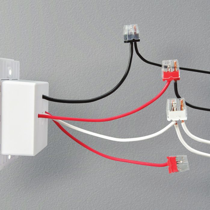
ENGLISH   TABLE OF CONTENTS

              Important safety information    4
              Overview                        7
              Parts included                  8
              Installation                   10
              • Double gang box
              • Single gang box
              • Main unit
              Configuring Relay              24
              • Logging into Wink
              • Customizing Relay
              Features                       26
              Warranty                       28
              Compliance                     30
              Troubleshooting                34

2                                                 3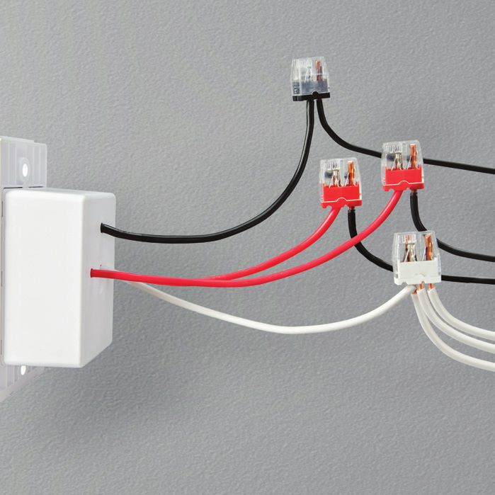
IMPORTANT SAFETY INFORMATION

        Carefully read all safety information before installing.          instructions, and installed/or used in accordance with
                                                                          appropriate electrical codes and regulations.
        WARNING: RISK OF ELECTRIC SHOCK                               •   Only use this device with copper or copper-clad wires.
    •   Before installing, servicing, or removing Relay,              •   Relay can ONLY be installed in a light load gang box
        TURN OFF POWER AT CIRCUIT BREAKER.                                (a gang box that controls lights only.)
    •   After power has been turned off, make sure the light          •   Relay can only be used in a single or double gang box
        switch you are going to replace with Relay is powered             where a neutral wire is present. Do not install in a multi-
        down before continuing installation.                              gang box unit.
        NOTE: It is recommended to use a circuit tester
        to make sure the circuit is off.                              •   Relay is not compatible with a 3-way light switch.
                                                                      •   Relay replaces single or double light switches not wired
    •   Installation involves handling high-voltage wires;
                                                                          to an AC outlet.
        follow warnings and safety instructions carefully.
    •   IF YOU ARE UNSURE ABOUT ANY OF THE                            •   The included wire stripper has an exposed blade which
        INSTRUCTIONS, CONSULT A QUALIFIED ELECTRICIAN.                    could potentially cause injury. Use with caution.
                                                                      •   Use this device only for its intended purpose as
        CAUTIONS & REQUIREMENTS                                           described in this user guide.
    •   Relay can ONLY connect to a 2.4GHz router
        broadcasting with a 20 MHz bandwidth.
    •   Relay must be installed in accordance with the installation

4                                                                                                                                       5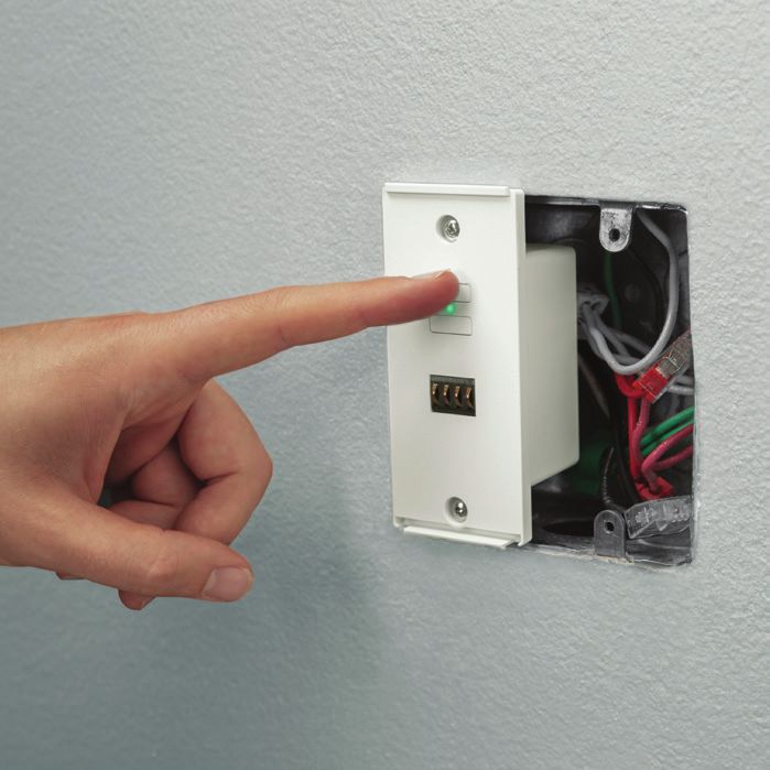
OVERVIEW

    GET INSTANT ACCESS TO
    YOUR CONNECTED HOME
    ON A TOUCHSCREEN
    THAT’S TAILORED TO YOU.
    CONTROL SMART LIGHTS,
    LOCKS, WINDOWS, A/Cs,
    AND MORE, ALL FROM
    WINK RELAY.

6                             7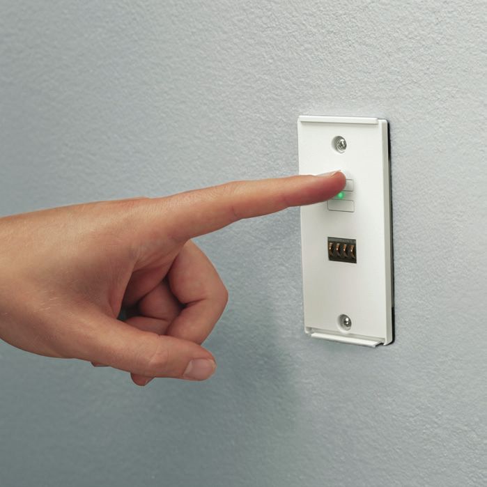
PARTS INCLUDED

                                                                                                 WIRE
                                            USER GUIDE                                        CONNECTOR**

                                           SCREWDRIVER

                MAIN UNIT   POWER BOX        SCREWS (2)               WIRE STRIPPER*         SNAP PL ATES (2)

                                        ** Wire stripper is provided in case your wires need to be trimmed
                                           or stripped for proper installation.
                                        ** A push-in wire connector works as a ‘finger trap’ for wires;
                                           simply push wires into an available pole to lock.
8                                                                                                            9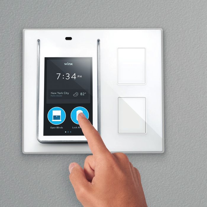
INSTALLATION
1 WARNING: RISK OF ELECTRIC SHOCK
Disconnect power to switch at the circuit breaker.
Test the existing light switch to make sure the circuit
breaker is off.
IF YOU ARE UNSURE ABOUT ANY OF THE INSTRUCTIONS,
CONSULT A QUALIFIED ELECTRICIAN.
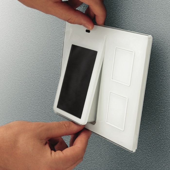
2 Separate power box from main unit by gently pulling the
base of the power box up and away from the back of Relay.
3 Remove existing wall plate and light switch.
10 11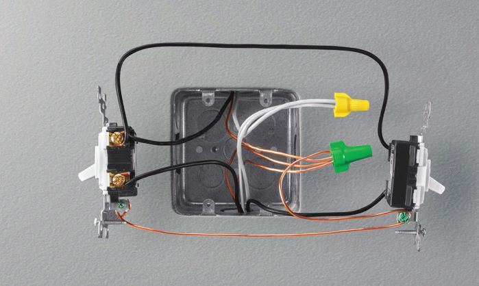
4 Identify the line, 1 load, 2 and neutral wires,             3
   then disconnect from existing switch.
       IF THERE ARE NO NEUTRAL WIRES, STOP AND CALL US
       AT 1-844-WINKAPP.                                                               3

 5     Disconnect wires from existing switches.
                                                                               1
 6     Cut and strip wires, if necessary.
       TO TRIM WIRES:
     • Place wire in the trimming notch closest to the spring at the spot
       it should be cut and press handle.
                                                                                   2
       TO STRIP WIRES:
     • Place insulated wire in the stripping notch that fits the wire gauge.
       Press and hold handle closed. Rotate wire until a cut is made around
       the insulation and pull insulation off the wire.

12                                                                                         13
DOUBLE GANG BOX INSTALLATION (RECOMMENDED)
     A double gang box is a double light switch that controls
     two loads.                                                            1

 7   Connect wires from gang box to wires on the power box.
     NOTE: Colors of wires may vary depending on your gang box.
     Consult a qualified electrician if you are unsure about a wire.

     Connect the line wire from the gang box (usually black)
                                                                                   2
     to the black 2-pole connector on the power box. 1
                                                                       3
 		Connect one of the load wires from the gang box
   (usually black) to one of the red 2-pole connectors
   on the power box. 2

     Connect the other load wire from the gang box (usually black)             4
     to the other red 2-pole connector on the power box. 3

     Connect the neutral wire(s) from the gang box (usually
     white) to the white 4-pole connector on the power box.       4

 8   There are no bare copper (ground) wires on the power box,
     however there will be ground wires in your wall; connect them
     all using the green 4-pole wire connector (included.)
     NOTE: Your ground wires may already be attached together
     with a connector. If this is the case, you will not need to
     complete this step. WARNING: Cap any loose wires.
14                                                                                     15
9   Push all wires back into wall as far as possible.

 10 Screw power box in place with the two (2) screws provided.
    Depending on the size of your wall opening, the powerbox
    may or may not fit completely inside the wall. Do not screw
    the powerbox flush with the wall.

 11 Turn power back on at circuit breaker.

 12 On the front of the power box, you will see two buttons
    and an LED light. If wired correctly, the LED light will
    be solid green.

     Press and hold the top button: the light attached to
     load 1 should turn on. Press and hold the bottom button:
     the light attached to load 2 should turn on. If the LED light
     does not light up green, see Troubleshooting section.

16                                                                   17
SINGLE GANG BOX INSTALLATION
     A single gang box is a single light switch that controls one load.
     Since Relay has the ability to control two light loads, installation   1
     in a gang box that has two loads running to it is preferred.

 7   Connect wires from gang box to wires on power box.
     NOTE: Colors of wires may vary depending on your gang box.
     Consult a qualified electrician if you are unsure about a wire.

     Connect the line wire from the gang box (usually black)                            2

     to the black 2-pole connector on the power box. 1

     Connect one of the load wires from the gang box
     (usually black) to one of the red 2-pole connectors
     on the power box. 2
                                                                                3
     Connect the neutral wire(s) from the gang box (usually
     white) to the white 4-pole connector on the power box.          3

 8   There are no bare copper (ground) wires on the power box,
     however there will be ground wires in your wall; connect them
     all using the green 4-pole wire connector (included).
     NOTE: Your ground wires may already be attached together
     with a connector. If this is the case, you will not need to
     complete this step. WARNING: Cap any loose wires.                              UNUSED

18                                                                                           19
9 Push all wires back into wall as far as possible.
10 Screw power box in place with the two (2) screws provided.
Depending on the size of your wall opening, the powerbox
may or may not fit completely inside the wall. Do not screw
the powerbox flush with the wall.
11 Turn power back on at circuit breaker.
12 On the front of the power box, you will see two buttons
and an LED light. If wired correctly, the LED light will
be solid green.
Press and hold the button the light was wired to: the light
should turn on. If the LED light does not light up green,
see Troubleshooting section.
20 21INSTALLING THE MAIN UNIT
The main unit attaches to the power box in one of three
positions (left, center, right) using one of the three ports
on the back of the unit.
13 Once you have decided which position you want, place
the snap plates (included) over the unused ports and snap
them into place.
14 Gently hook and press the main unit's uncovered ports
onto the power box and snap it into place.
You are now ready to start configuring Relay!
22 23CONFIGURING RELAY
Connecting Relay to Wink is easy. Follow the step-by-step
instructions that appear on the Relay screen.
LOGGING INTO WINK
1 Relay will automatically turn on once it’s connected to the
power box and power has been restored to the circuit breaker.
2 Instructions on Relay's screen will walk you through the
Wi-Fi pairing process.
NOTE: Relay must be connected to Wi-Fi to operate.
If Relay does not connect to your Wi-Fi network, see
Troubleshooting section.
3 Log in or create a Wink account.
CUSTOMIZING RELAY
After setting up your Wink Relay, you can customize Wink Relay
through the Wink app on your smartphone. 3 Create or sign into your Wink account.
1 Connect your smartphone to your Wi-Fi network 4 Go to Relay in your Wink app where you can customize
(enter network name and password). your Relay.
2 Download or launch the Wink app from the Apple App Store For more information and further set up assistance,
or Google Play. please visit wink.com/relay
24 25FEATURES
5
1 4.3" multi-touch LCD display.
2 2x smart switches trigger lights or user preset actions.
Designed to control up to two (2) light loads.
1
3 Microphone and speaker for intercom functionality. 2
4 Temperature and humidity sensor.
5 Proximity sensor:
Bluetooth® Low Energy (BLE) allows Relay
to recognize which user is present via their
smartphone and activates their stored user profile.
NOTE: Runs the Wink app
(Wi-Fi®, Bluetooth®, and ZigBee® compatible.)
3
4
26 27WARRANTY
LIMITED ONE-YEAR WARRANTY THIS WARRANTY CONTAINS THE SOLE WARRANTY OF WINK.
Wink, Inc. ("Wink") Original Purchase Product Warranty THERE ARE NO OTHER WARRANTIES, EXPRESSED OR IMPLIED,
INCLUDING THE IMPLIED WARRANTY OR CONDITION OF
Wink warrants to the original purchaser ("Purchaser") of this Wink QUALITY, MERCHANTABILITY OR FITNESS FOR A PARTICULAR
product, for the period of one (1) year following the date on which PURPOSE, AND SUCH IMPLIED WARRANTIES, IF ANY, ARE
Purchaser purchases the product, that the product shall be free of LIMITED IN DURATION TO THE TERM OF THIS WARRANTY. IN
defects in design, assembly, material, or workmanship. Wink will NO EVENT SHALL WINK BE LIABLE FOR INCIDENTAL, SPECIAL,
refund or replace, at its option, any defective product free of charge. DIRECT, INDIRECT OR CONSEQUENTIAL DAMAGES SUCH AS, BUT
In order to qualify for this warranty, the Purchaser must provide the NOT LIMITED TO, LOST BUSINESS OR PROFITS ARISING OUT OF
defective product and a copy of the original receipt of purchase to THE SALE OR USE OF ANY WINK PRODUCT, EVEN IF ADVISED OF
Wink for inspection. The receipt of purchase must indicate the product THE POSSIBILITY OF SUCH DAMAGES.
purchased, price paid, date of purchase, and name of merchant. Some jurisdictions do not allow exclusions or limitations on implied
To request service under this warranty, contact Wink at 1-844-WINK- warranties or incidental, consequential or other damages, so the
APP or support@wink.com and a Wink representative will provide above exclusions and limitations may not apply to you.
instruction on how to proceed.
This warranty shall be null and void if Wink determines that the product
has been improperly installed, altered or tampered with in any way.
This warranty does not protect against normal use, wear and tear, or
damage due to abuse.
28 29COMPLIANCE
FCC STATEMENTS CAUTION: Any changes or modifications not expressly approved by
the party responsible for compliance could void the user's authority
This device complies with Part 15 of the FCC Rules. Operation is
to operate this equipment.
subject to the following two conditions: (1) this device may not cause
harmful interference, and (2) this device must accept any interference
received, including interference that may cause desired operation.
FCC RADIATION EXPOSURE STATEMENTS:
NOTE: This equipment has been tested and found to comply with
the limits for a Class B digital device, pursuant to Part 15 of the FCC This equipment complies with FCC radiation exposure limits set forth
Rules. These limits are designed to provide reasonable protection for an uncontrolled environment. This equipment should be installed
against harmful interference in a residential installation. This equipment and operated with minimum distance 20cm between the radiator and
generates, uses and can radiate radio frequency energy and, if not your body.
installed and used in accordance with the instructions, may cause NOTE: The country code selection is for non-US model only and is not
harmful interference to radio communications. However, there is no available to all US model. Per FCC regulation, all Wi-Fi product marketed
guarantee that interference will not occur in a particular installation. in US must fixed to US operation channels only.
If this equipment does cause harmful interference to radio or television
reception, which can be determined by turning the equipment off and
on, the user is encouraged to try to correct the interference by one
of the following measures:
• Reorient or relocate the receiving antenna.
• Increase the separation between the equipment and receiver.
• Connect the equipment into an outlet on a circuit different from
that to which the receiver is connected.
• Consult the dealer or an experienced radio/TV technician for help.
30 31INDUSTRY CANADA STATEMENTS PRODUCT RATING
This device complies with Industry Canada licence-exempt RSS standard(s). 120VAC, 60Hz, 3A, 360W, Tungsten per each output
Operation is subject to the following two conditions: (1) this device may
not cause interference, and (2) this device must accept any interference, 120VAC, 60Hz, 8A, 960W, General Purpose per each output
including interference that may cause undesired operation of the device.
COPYRIGHT NOTICE
RADIATION EXPOSURE STATEMENTS Copyright 2014 Wink, Inc.
This equipment complies with IC radiation exposure limits set forth for an Wink is a trademark of Wink, Inc.
uncontrolled environment. This equipment should be installed and operated
with minimum distance 20cm between the radiator and your body. No part of this manual may be reproduced
or modified without written consent from Wink, Inc.
Wi-Fi is a registered trademark of the Wi-Fi Alliance.
Bluetooth is a registered trademark of SIG, Inc.
ZigBee is a registered trademark of ZigBee Alliance.
32 33TROUBLESHOOTING
ISSUE SOLUTION
Won't power up Check the wiring.
Not connecting Check your router settings:
to Wi-Fi 1 Relay can ONLY connect to a 2.4GHz
router broadcasting with a 20 MHz bandwidth.
When using a dual band router: Dual band routers
operate in 2.4GHz and 5GHz modes simultaneously.
Relay CANNOT connect to the 5GHz network, it can
ONLY connect to the 2.4GHz network. Relay can
ONLY connect to the 2.4GHz router broadcasting with CUSTOMER SERVICE
a 20 MHz bandwidth, NOT when the 2.4GHz router is
broadcasting with a 40MHz bandwidth.
If you need any help, we have your back with a customer
2 Check that security is set to WPA-PSK not WEP. support team that is available 7 days a week.
Email us at support@wink.com
I have Check the wiring instructions. or call 1-844-WINK-APP to speak to a real person.
extra wires
34 35FRANÇAIS TABLE DES MATIÈRES
Informations importantes en 38
matière de sécurité
Vue d’ensemble 41
Pièces incluses 42
Installation 44
• Boîtier double
• Boîtier simple
• Unité principale
Configuration de Relay 58
• Connexion à Wink
• Personnalisation de Relay
Caractéristiques 60
Garantie 62
Conformité 64
Dépannage 68
36 37INFORMATIONS IMPORTANTES EN MATIÈRE DE SÉCURITÉ
Lisez attentivement toutes les informations concernant • Relay doit être installé conformément aux instructions
la sécurité avant l’installation. d'installation, et installé / ou utilisé suivant les normes
et régulations électriques appropriées.
AVERTISSEMENT : RISQUE DE DÉCHARGE ÉLECTRIQUE • Utilisez cet appareil seulement avec du fil de cuivre
• Avant l’installation, l’entretien ou le retrait de Relay, ou couvert de cuivre.
COUPEZ L’ALIMENTATION AU DISJONCTEUR. • Relay doit SEULEMENT être installé dans un boîtier
de charge d’éclairage (un boîtier qui contrôle
• Après que l’alimentation soit coupée, assurez-vous que l’éclairage seulement.)
l’interrupteur que vous voulez remplacer par Relay soit
mis hors tension avant de continuer l’installation. • Relay doit seulement être utilisé dans un boîtier simple
REMARQUE : Il est recommandé d’utiliser un multimètre ou double où un fil neutre est présent. Ne pas installer
pour vous assurer que le circuit soit hors tension. dans une unité de boîtier multiple.
• Relay n'est pas compatible avec un boîtier d’éclairage
• L’installation implique la manutention de fils à haute
triple.
tension, suivez les avertissements et les instructions
de sécurité attentivement. • Relay remplace les plaques d’interrupteur simples ou
doubles qui ne sont pas branchées à une prise CA.
• SI VOUS ÊTES INCERTAIN D’UNE CONSIGNE, CONSULTEZ
UN ÉLECTRICIEN QUALIFIÉ. • Le couteau à dénuder inclus possède une lame exposée qui
pourrait entraîner une blessure. Utilisez avec prudence.
AVERTISSEMENTS ET EXIGENCES • Utilisez cet appareil uniquement pour son usage prévu
• Relay peut SEULEMENT se connecter à un routeur de comme décrit dans ce guide de l’utilisateur.
2,4 GHz diffusant avec une largeur de bande de 20 MHz.
38 39VUE D’ENSEMBLE
OBTENEZ UN ACCÈS
INSTANTANÉ À VOTRE
MAISON CONNECTÉE
SUR UN ÉCRAN TACTILE
PERSONNALISÉ POUR VOUS.
CONTRÔLEZ L’ÉCLAIRAGE, LES
SERRURES, LES FENÊTRES, LES
CLIMATISEURS INTELLIGENTS
ET PLUS, TOUT À PARTIR DE
WINK RELAY.
40 41PIÈCES INCLUSES
CAPUCHON DE
GUIDE DE CONNEXION**
L’UTILISATEUR
TOURNEVIS
UNITÉ PRINCIPALE BOÎTIER VIS (2) COUTEAU À DÉNUDER* PLAQUES
D’ALIMENTATION D'ACCROCHAGE (2)
** Un couteau à dénuder est fourni, au cas où vos fils devraient être
coupés ou dénudés pour une installation adéquate.
** Un connecteur à enfichage fonctionne comme une « sécurité anti-
pincement » pour les fils; poussez simplement les fils dans un pôle
disponible pour verrouiller.
42 43INSTALLATION
1 AVERTISSEMENT : RISQUE DE DÉCHARGE ÉLECTRIQUE
Coupez l’alimentation de l’interrupteur au disjoncteur.
Testez l’interrupteur d’éclairage existant pour vous assurer
que le disjoncteur est coupé.
SI VOUS ÊTES INCERTAIN D’UNE CONSIGNE, CONSULTEZ
UN ÉLECTRICIEN QUALIFIÉ.
2 Séparez le boîtier d’alimentation de l’unité principale en tirant
doucement la base du boîtier d’alimentation vers le haut et en
l'éloignant du dos de Relay.
3 Enlevez la plaque et l’interrupteur d’éclairage existants
du mur.
44 454 Identifiez les fils de ligne 1 , de charge 2 et neutre 3
puis déconnectez l’interrupteur existant.
S'IL N'Y A PAS DE FILS NEUTRES, ARRÊTEZ-VOUS ET
APPELEZ 1-844-WINKAPP. 3
5 Débranchez les fils de l'interrupteur existants.
1
6 Coupez et dénudez les fils, si nécessaire.
POUR COUPER LES FILS :
• Placez le fil à l'endroit où il doit être coupé, dans l'encoche
à couper la plus proche du ressort du couteau a dénuder.
Serrez complètement la poignée. 2
POUR DÉNUDER LES FILS :
• Placez le fil isolé dans l'encoche à dénuder qui correspond
au calibre du fil. Serrez en tenant la poignée fermée, tournez
le fil jusqu'à ce qu'une incision soit faite toute autour de l'isolant
puis tirez l'isolant du fil.
46 47INSTALLATION D’UN BOÎTIER DOUBLE (RECOMMANDÉ)
Un boîtier double est un interrupteur d’éclairage double
1
qui contrôle deux charges.
7 Connectez les fils du boîtier aux fils de la boîte d’alimentation.
REMARQUE : Les couleurs des fils peuvent varier en
fonction de votre boîtier. Consultez un électricien qualifié
si vous êtes incertain d’un fil.
Connectez le fil de ligne (actif et normalement noir) au 2
connecteur noir à 2 pôles sur la boîte d’alimentation. 1 3
Connectez un des fils de charge du boîtier (normalement
noir) à un des connecteurs rouge à 2 pôles sur la boîte
d’alimentation. 2
Connectez l’autre fil de charge du boîtier (normalement 4
noir) à l’autre connecteur rouge à 2 pôles sur la boîte
d’alimentation. 3
Connectez le fil neutre du boîtier (normalement blanc) au
connecteur blanc à 4 pôles sur la boîte d’alimentation. 4
8 Il n’y a pas de fils de cuivre nus (mise à la terre) sur la boîte
d’alimentation, par contre il y aura des fils de mise à la
terre dans votre mur; connectez-les tous en utilisant le
connecteur vert à 4 pôles (inclus .)
48 49REMARQUE : Il se peut que vos fils de mise à la terre
soient attachés avec un connecteur. Si c’est le cas, il n’est
pas nécessaire de réaliser cette étape. AVERTISSEMENT :
Protégez les fils libres avec des capuchons de connexion.
9 Poussez tous les fils dans le mur aussi loin que possible.
10 Fixez la boîte d’alimentation en place avec les deux (2)
vis fournies. En fonction de la taille de l'ouveture de
votre mur, il se peut que la boîte d'alimentation s'insère
complétement ou non dans le mur. Ne pas visser la boîte
d'alimentation de manière lisse contre le mur.
11 Rétablissez l’alimentation au disjoncteur.
12 Sur le devant de la boîte d’alimentation, vous verrez deux
boutons et un voyant à DEL. Si tout est bien raccordé, le
voyant à DEL sera vert.
Maintenez appuyé le bouton du haut : l'éclairage attaché
à la charge 1 devrait s’allumer. Maintenez appuyé le bouton
du bas : l'éclairage attaché à la charge 2 devrait s’allumer.
Si le voyant à DEL ne s’allume pas en vert, voir la section
Dépannage.
50 51INSTALLATION D’UN BOÎTIER SIMPLE
Un boîtier simple est un interrupteur d’éclairage simple qui
1
contrôle une charge. Comme Relay a la capacité de contrôler
deux charges d’éclairage, l’installation dans un boîtier alimenté
par deux charges est préférable.
7 Connectez les fils du boîtier aux fils de la boîte d’alimentation.
REMARQUE : Les couleurs des fils peuvent varier en
fonction de votre boîtier. Consultez un électricien qualifié
2
si vous êtes incertain d’un fil.
Connectez le fil de ligne du boîtier (actif et normalement
noir) au connecteur noir à 2 pôles sur la boîte d’alimentation. 1
Connectez un des fils de charge du boîtier (normalement
noir) à un des connecteurs rouge à 2 pôles sur la boîte
3
d’alimentation. 2
Connectez le fil neutre du boîtier (normalement blanc)
au connecteur blanc à 4 pôles sur la boîte d’alimentation. 3
8 Il n’y a pas de fils de cuivre nus (mise à la terre) sur la boîte
d’alimentation, par contre il y aura des fils de mise à la
terre dans votre mur; connectez-les tous en utilisant le
connecteur vert à 4 pôles (inclus.)
UNUSED
52 53REMARQUE : Il se peut que vos fils de mise à la terre
soient attachés avec un connecteur. Si c’est le cas, il n’est
pas nécessaire de réaliser cette étape. AVERTISSEMENT :
Protégez les fils libres avec des capuchons de connexion.
9 Poussez tous les fils dans le mur aussi loin que possible.
10 Fixez la boîte d’alimentation en place avec les deux (2)
vis fournies. En fonction de la taille de l'ouveture de
votre mur, il se peut que la boîte d'alimentation s'insère
complétement ou non dans le mur. Ne pas visser la boîte
d'alimentation de manière lisse contre le mur.
11 Rétablissez l’alimentation au disjoncteur.
12 Sur le devant de la boîte d’alimentation, vous verrez deux
boutons et un voyant à DEL. Si tout est bien raccordé,
le voyant à DEL sera vert.
Appuyez et maintenez le bouton qui était relié à l'éclairage :
la lumière devrait s'allumer. Si le voyant à DEL ne s’allume
pas en vert, voir la section Dépannage.
54 55INSTALLATION DE L’UNITÉ PRINCIPALE
L’unité principale s’attache à la boîte d’alimentation dans
l’une de trois positions (gauche, centre, droite) à l’aide
d’un des trois ports situés au dos de l’unité.
13 Une fois que vous avez choisi la position désirée, placez
les plaques d'accrochage (incluses) au-dessus des ports
inutilisés et enclenchez-les.
14 Accrochez le port non couvert de l’unité principale
sur la boîte d’alimentation en appuyant doucement
et enclenchez-la.
Vous êtes maintenant prêt à commencer
la configuration de Relay !
56 57CONFIGURATION DE RELAY
La connexion de Relay à Wink est facile. Suivez les instructions
étape par étape qui s’affichent sur l’écran Relay.
CONNEXION À WINK
1 Relay s’activera automatiquement une fois raccordé à la boîte
d’alimentation et l’alimentation restaurée au disjoncteur.
2 Les instructions sur l’écran vous guideront dans le processus
de jumelage Wi-Fi.
REMARQUE : Relay doit être connecté à Wi-Fi pour
fonctionner. Si Relay ne peut se connecter à votre réseau
Wi-Fi, voir la section Dépannage.
3 Ouvrez une session ou créez un compte Wink.
PERSONNALISATION DE RELAY
Après la mise en place de votre Wink Relay, vous pouvez
personnaliser Wink Relay par le biais de l’application Wink
sur votre téléphone intelligent. 3 Créez votre compte Wink ou ouvrez une session.
1 Connectez votre téléphone intelligent à votre réseau Wi-Fi 4 Allez à Relay dans votre application Wink, où vous pourrez
(entrez le nom de réseau et le mot de passe.) personnaliser votre Relay.
2 Téléchargez ou lancez l’application Wink de l’App Store d’Apple Pour plus d’informations et pour de l’aide supplémentaire,
ou de Google Play. veuillez visiter wink.com/relay
58 59CARACTÉRISTIQUES
5
1 Écran multitouches ACL de 4,3 po.
2 2 interrupteurs intelligents déclenchant l’éclairage
ou les actions préréglées par l’utilisateur.
Conçu pour contrôler jusqu’à deux (2) charges d’éclairage. 1
3 Microphone et haut-parleur pour une fonctionnalité 2
d’intercom.
4 Capteur de température et d’humidité intégré.
5 Capteur de proximité :
Bluetooth® Low Energy (BLE) permet à Relay de
reconnaître quel utilisateur est présent par le biais d’une
connexion à son téléphone intelligent et d’activer son
profil d’utilisateur sauvegardé.
REMARQUE : Exécute l’application Wink
(compatible avec Wi-Fi®, Bluetooth® et ZigBee®.)
3
4
60 61GARANTIE
GARANTIE LIMITÉE D’UN AN CETTE GARANTIE CONSTITUE L’ENTIÈRE GARANTIE DE WINK.
Wink, Inc. (« Wink ») Garantie du produit à l’achat initial IL N’EXISTE AUCUNE AUTRE GARANTIE, EXPRESSE OU IMPLICITE,
Y COMPRIS UNE GARANTIE IMPLICITE OU UNE GARANTIE
Wink garantit à l’acheteur initial (« Acheteur ») de ce produit Wink, DE QUALITÉ MARCHANDE OU D’APTITUDE À UN EMPLOI
pour une période d’un (1) an suivant la date d’achat de ce produit par PARTICULIER, ET DE TELLES GARANTIES IMPLICITES, LE CAS
l’Acheteur, que le produit est exempt de tout vice de conception, ÉCHÉANT, SE LIMITENT À LA DURÉE DE LA PRÉSENTE GARANTIE.
d’assemblage, de matériel ou de fabrication. Wink remboursera ou SOUS AUCUN PRÉTEXTE WINK NE SAURAIT ÊTRE TENUE
remplacera, à sa discrétion, tout produit défectueux, sans frais. RESPONSABLE DE TOUS DOMMAGES ACCESSOIRES, SPÉCIAUX,
Pour être admissible à cette garantie, l’Acheteur doit fournir le DIRECTS, INDIRECTS OU IMMATÉRIELS Y COMPRIS, ENTRE
produit défectueux et une copie du reçu original de l’achat à Wink AUTRES, LES PERTES D’AFFAIRES OU DE PROFITS DÉCOULANT DE
pour inspection. Le reçu doit indiquer le produit acheté, le montant LA VENTE OU DE L’UTILISATION DE TOUT PRODUIT, MÊME SI DE
déboursé, la date d’achat et le nom du commerçant. TELS DOMMAGES ÉTAIENT CONSIDÉRÉS COMME POSSIBLES.
Pour demander un service couvert par cette garantie, contactez Wink Certaines collectivités publiques ne permettent pas les exclusions ou
au 1-844-WINK-APP ou à support@wink.com et un représentant les limitations des garanties implicites sur les dommages accessoires,
Wink vous indiquera la marche à suivre. immatériels ou autres, et les exclusions et les limitations ci-dessus
peuvent donc ne pas s’appliquer à vous.
Cette garantie sera nulle et non avenue si Wink détermine que le
produit a été mal installé, altéré ou modifié de quelque façon que ce
soit. Cette garantie ne protège pas l’Acheteur contre l’usage normal,
l’usure ou les dommages causés par une mauvaise utilisation.
62 63CONFORMITÉ
ÉNONCÉS DE LA FCC MISE EN GARDE : Tout changement ou toute modification non
approuvé(e) expressément par la partie responsable de la conformité
Cet appareil respecte la Partie 15 des réglementations de la FCC.
pourrait annuler le droit de l’utilisateur d’utiliser l’équipement.
L’exploitation est sujette aux deux conditions suivantes : (1) l’appareil ne
doit pas produire d’interférence nuisible, et (2) l’appareil doit accepter
toute interférence subie, même si l’interférence est susceptible d’en
compromettre le fonctionnement. ÉNONCÉS DE LA FCC PORTANT SUR L’EXPOSITION AUX
RAYONNEMENTS :
REMARQUE : Cet équipement a été testé et évalué comme respectant
les limites d’un appareil numérique de Classe B, conformément à la Cet équipement est conforme aux limites portant sur l’exposition aux
Partie 15 des réglementations de la FCC. Ces limites sont conçues rayonnements de la FCC établies pour un environnement non contrôlé.
pour offrir une protection raisonnable contre les interférences Cet équipement doit être installé et utilisé avec une distance minimale
dommageables dans une installation résidentielle. Cet équipement de 20 cm entre la source de rayonnement et votre corps.
génère, utilise et peut émettre de l’énergie de fréquence radio
REMARQUE : La sélection de code de pays s’applique au modèle
et, s’il n’est pas installé et utilisé conformément aux instructions,
non américain seulement et n’est pas disponible sur tous les modèles
peut causer une interférence dommageable aux communications
américains (pour les États-Unis). Selon la réglementation de la FCC,
radio. Cependant, il n’y a aucune garantie quant à la présence
tout produit Wi-Fi commercialisé aux États-Unis doit être réglé sur des
d’interférence dans une installation précise. Si cet équipement cause
canaux d’opération des États-Unis seulement.
une interférence dommageable à la réception radio ou télévisuelle,
ce qui peut être déterminé en éteignant et en allumant l’équipement,
nous encourageons l’utilisateur à tenter de corriger l’interférence en
appliquant une ou plusieurs des mesures suivantes :
• Rediriger ou déplacer l’antenne réceptrice.
• Augmenter la distance séparant l’équipement et le récepteur.
• Brancher l’équipement à une prise liée à un circuit différent de celui
du récepteur.
• Consulter le vendeur ou un technicien en radio/télévision
expérimenté pour obtenir de l’assistance.
64 65ÉNONCÉS D’INDUSTRIE CANADA CARACTÉRISTIQUES ÉLECTRIQUES DU PRODUIT
Le présent appareil est conforme aux CNR d’Industrie Canada 120VAC, 60Hz, 3A, 360W, tungstène pour chaque sortie
applicables aux appareils radio exempts de licence. L’exploitation
est autorisée aux deux conditions suivantes: (1) l’appareil ne doit pas 120VAC, 60Hz, 8A, 960W, usage général pour chaque sortie
produire d’interférence, et (2) l’utilisateur de l’appareil doit accepter
toute interférence radioélectrique subie, même si l’interférence est
susceptible d’en compromettre le fonctionnement. AVIS DE DROIT D’AUTEUR
Copyright 2014 Wink, Inc.
ÉNONCÉS PORTANT SUR L’EXPOSITION AUX RAYONNEMENTS Wink est une marque de commerce de Wink, Inc.
Cet équipement est conforme aux limites d’exposition aux Aucune partie de ce manuel ne peut être reproduite ou modifiée sans
rayonnements IC établies pour un environnement non contrôlé. Cet le consentement écrit de Wink, Inc.
équipement doit être installé et utilisé avec un minimum de 20 cm de Wi-Fi est une marque de commerce déposée de Wi-Fi Alliance.
distance entre la source de rayonnement et votre corps.
Bluetooth est une marque de commerce déposée de SIG, Inc.
ZigBee est une marque de commerce déposée de ZigBee Alliance.
66 67DÉPANNAGE
PROBLÈME SOLUTION
Ne démarre pas Vérifiez les fils.
Ne se connecte Vérifiez les paramètres de votre routeur :
pas à Wi-Fi 1 Relay peut SEULEMENT se connecter à un
routeur de 2,4 GHz diffusant avec une largeur
de bande de 20 MHz.
Lors de l’utilisation d’un routeur bibande : Les
routeurs bibande fonctionnent dans les modes
2,4 GHz et 5 GHz simultanément. Relay NE PEUT PAS
se connecter à un réseau 5 GHz, il peut SEULEMENT SERVICE À LA CLIENTÈLE
se connecter au réseau 2,4 GHz.
Relay peut SEULEMENT se connecter à un routeur Si vous avez besoin d’aide, nous sommes là pour vous
de 2,4 GHz diffusant avec une largeur de bande de avec une équipe de service à la clientèle qui est disponible
20 MHz, ET NON quand le routeur 2,4 GHz diffuse 7 jours par semaine.
avec une largeur de bande de 40 MHz.
2V
érifiez que la sécurité est réglée à WPA-PSK Envoyez-nous un courriel à support@wink.com
et non WEP. ou composez le 1-844-WINK-APP pour parler avec
J’ai des fils Vérifiez les instructions d'installation. l’un de nos agents.
supplémentaires
68 6970 71
R-INS-RLAY-WH01 | rev102414
72
Vous pouvez aussi lire