User Manual AC-Coupled Inverter A-BP Series V1.3-2022-01-05 - GoodWe

La page est créée Sonia Antoine
 
CONTINUER À LIRE
User Manual AC-Coupled Inverter A-BP Series V1.3-2022-01-05 - GoodWe
User Manual
AC-Coupled Inverter
          A-BP Series
         V1.3-2022-01-05
User Manual AC-Coupled Inverter A-BP Series V1.3-2022-01-05 - GoodWe
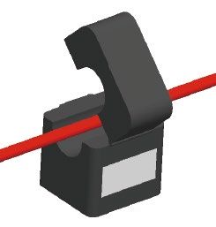
Content                                                                                        User Manual V1.3

                          TABLE OF CONTENTS
01 Introduction......................................................................1
 1.1 Operation Modes Introduction.................................................................1
 1.2 Safety and Warning....................................................................................2
 1.3 Product Overview.......................................................................................6
 1.4 User Interface Introduction......................................................................7

02 Installation Instructions.................................................8
 2.1 Unacceptable Installations........................................................................8
 2.2 Packing List.................................................................................................9
 2.3 Mounting.....................................................................................................9
  2.3.1 Select Mounting Location.................................................................................. 9
  2.3.2 Wall Mounted Bracket And Inverter Installation..........................................10
 2.4 Conduit and Wiring Installation.............................................................13
  2.4.1 Wiring Box Conduit Plugs................................................................................14
  2.4.2 Battery Wiring Connection..............................................................................14
  2.4.3 On-Grid / AC Connection..................................................................................16
  2.4.4 Back-up Connection.........................................................................................18
  2.4.5 Auto-transformer Connection (Optional)......................................................22
  2.4.6 CT Connections.................................................................................................25
  2.4.7 Battery BMS Connection..................................................................................26
  2.4.8 WiFi Communication Connection...................................................................27
 2.5 PV Master App..........................................................................................27
 2.6 Wiring System For A-BP Series Inverter (Full Backup).........................28
 2.7 Wiring System For A-BP Series Inverter(Partial Backup).....................30

                                                          2
User Manual V1.3                                                                                          Content

 03 OTHER...............................................................................32
  3.2 Troubleshooting.......................................................................................34
  3.3 Disclaimer..................................................................................................37
  3.4 Technical Parameters .............................................................................38
    3.4.1 Inverter Specification.......................................................................................38
    3.4.2 Auto-transformer Specfication.......................................................................42
    3.4.3 Grid Parameter Setting ...................................................................................43
  3.5 Maintenance.............................................................................................44
    3.5.1 Clearing and Replacing Fans...........................................................................44
    3.5.2 Fuse Replacement............................................................................................45
    3.5.3 About Periodical Maintenance........................................................................46

 Appendix...............................................................................47

                                                           3
01 Introduction                                                             User Manual V1.3

01 Introduction
The A-BP series, also called AC-coupled or bidirectional inverters, provides energy management
in a PV system that includes solar modules (or not), a battery, loads, and utility grid connection.
Energy produced by the PV system will be used to optimize self-consumption, excess will be used
to charge the battery, anymore could be exported to the grid. The battery shall discharge to
support loads when PV power is insufficient to meet self-consumption needs. If battery power is
not sufficient, the system will take power from the utility grid to support loads.
When the A-BP inverter is operating in off-grid mode (disconnected the utility grid), it will create
a micro-grid. The PV Inverter will accept this micro-grid and will therefore operate even during a
black-out. Similar to on-grid mode: when the PV power exceeds the load, excess will be charged
the battery through the A-BP inverter.

1.1 Operation Modes Introduction
                              The preceding introduction describes the general operation
                              of the A-BP system. The operation mode can be changed
                              with the PV Master app based on the system layout. The
                              possible operation modes for the A-BP system are shown
                              below.

A-BP system normally has the following operation modes based on your configuration and
layout conditions.

Mode I                                               Mode II
Energy from PV inverter optimize loads,              When energy from PV inverter is weak,
excess will be used to charge the battery, any       battery will discharge to support the load in
remaining excess will be exported to the grid.       priority together with the grid.

Mode III                                             Mode IV
When grid power fails, A-BP inverter creates         Battery could be charged by grid, and
a micro grid, and the weight of the load
determines whether PV energy flows into the          charge time/power could be set flexibly on
load or charges the battery.                         PV Master APP.

                                                 1
User Manual V1.3                                                            01 Introduction

1.2 Safety and Warning
A-BP series AC-COUPLED inverter has been designed and tested in accordance with safety
requirements. As with power electronic devices, there are residual risks despite strict standards.
You are recommended to read the following information carefully to prevent personal injury and
property damage.
SAVE THESE INSTRUCTIONS - This manual contains important instructions for A-BP AC-COUPLED
INVERTER that shall be followed during installation and maintenance of the inverter.

                          These servicing instructions are for use by qualified personnel only.
                          To reduce the risk of electric shock, do not perform any servicing
       WARNING!           other than that specified in the operating instructions.
                          Ces instructions d’entretien sont destinées uniquement au personnel
                          qualifié. Pour réduire le risque de choc électrique, n’effectuez aucun
                          service autre que celui spécifié dans les instructions d’exploitation.
Symbol Explanation
                         DANGER indicates a hazardous situation which, if not avoided, will
                         result in death or serious injury.
        DANGER!          DANGER indique une situation dangereuse qui, si elle n’est pas évitée,
                         est susceptible de provoquer un décès ou des blessures graves.
                         WARNING indicates a hazardous situation which, if not avoided, could
       WARNING!          result in death or serious injury.
                         AVERTISSEMENT indique une situation dangereuse qui, si ellen’est pas
                         évitée, est susceptible de provoquer un décès ou des blessures graves.

                         CAUTION indicates a hazardous situation which, if not avoided, could
                         result in minor or moderate injury.
        CAUTION!         PRUDENCE indique une situation dangereuse qui, si elle n’est pas évitée,
                         est susceptible de provoquer des blessures légères ou de degré moyen.

             Danger of high voltage and electric shock!
             Danger de haute tension et de choc électrique !

             Hot Surface- To reduce the risk of burns-Do not touch.
             Surface chaude- Pour réduire le risque de brûlures- Ne touchez pas

             Components of the product can be recycled.
             Les composants du produit peuvent être recyclés.

             This side up! The package must always be transported, handled and stored in such
             a way as the arrows always point upwards.
             Ce côté vers le haut! Le paquet doit toujours être transporté, manipulé et stocké de
             manière à ce que les flèches pointent toujours vers le haut.

             No more than six (6) identical packages being stacked on each other.
             Pas plus de six (6) paquets identiques étant empilés les uns sur les autres.

             Products should not be disposed as household waste.
             Les produits ne doivent pas être éliminés comme déchets ménagers.

                                               2
01 Introduction                                                                  User Manual V1.3

               Fragile - The package/product should be handled carefully and never be tipped over
               or slung.
               Fragile - L’emballage/produit doit être manipulé avec soin et ne jamais être renversé
               ou en bandoulière.

               Refer to the operating instructions.
               Consultez les instructions d’exploitation.

               Keep dry! The package/product must be protected from excessive humidity and
               must be stored under cover.
               Restez au sec ! L’emballage/produit doit être protégé contre une humidité excessive
               et doit être stocké à couvert.

               This symbol indicates that you should wait at least 5mins after disconnecting the
               inverter from the utility grid and from the PV panel before touching any inner live parts.
        5min
               Ce symbole indique que vous devriez attendre au moins 5 minutes après avoir
               déconnecté l’onduleur de la grille d’utilité et du panneau PV avant de toucher les parties
               vivantes intérieures.

               CSA certified
               Certifié CSA

Safety Warnings
 Any installation and operation on inverter must be performed by qualified electricians, in
 compliance with standards, wiring rules or requirements of local authorities or grid company.
 Toute installation et fonctionnement sur onduleur doivent être effectués par des électriciens
 qualifiés, conformément aux normes, aux règles de câblage ou aux exigences des autorités
 locales ou de la société de réseau.

 The input and output circuits are isolated from the enclosure and that system grounding, if
 required by Sections 690.41, 690.42 and 690.43 of the National Electric Code, ANSI/NFPA 70, is
 the responsibility of the installer.
 Les circuits d’entrée et de sortie sont isolés de l’enceinte et cette mise à la terre du système,
 si nécessaire par les sections 690.41, 690.42 et 690.43 du Code national de l’électricité, ANSI/
 NFPA 70, est la responsabilité de l’installateur.

 Any operation on AC or DC terminals when inverter is operational is prohibited.
 Toute opération sur le terminal AC ou DC lorsque l’onduleur est en service est interdite.

 Before any wiring connection or electrical operation on inverter, all DC and AC power must be
 disconnected from inverter for at least 5 minutes to make sure inverter is totally isolated to
 avoid electric shock.
 Avant toute connexion de câblage ou de fonctionnement électrique sur onduleur, toute la
 puissance DC et AC doit être déconnectée de l’onduleur pendant au moins 5 minutes pour
 s’assurer que l’onduleur est totalement isolé pour éviter les chocs électriques.

 The temperature of inverter surface might exceed 60°C during operation, so please make
 sure it has cooled down before touching it, and make sure the inverter is out of reach of
 children.
 La température de la surface de l’onduleur peut dépasser 60 oC pendant l’opération, alors
 assurez-vous qu’elle s’est refroidie avant de la toucher, et assurez-vous que l’onduleur est hors
 de portée des enfants.

                                                     3
User Manual V1.3                                                           01 Introduction

Do not open the inverter's cover or change any components without manufacturer's
authorization, otherwise the warranty commitment for the inverter will be invalid.
N’ouvrez pas la couverture de l’onduleur ou ne modifiez aucun composant sans l’autorisation
du fabricant, sinon l’engagement de garantie pour l’onduleur sera invalide.

Usage and operation of the inverter must follow instructions in this user manual, otherwise
the protection design might be impared and warranty commitment for the inverter will be
invalid.
L’utilisation et le fonctionnement de l’onduleur doivent suivre les instructions contenues
dans ce manuel d’utilisation, sinon la conception de protection pourrait être imparée et
l’engagement de garantie pour l’onduleur sera invalide.

Appropriate methods must be adopted to protect inverter from electrostatic damage. Any
damage caused by static is not warranted by manufacturer.
Des méthodes appropriées doivent être adoptées pour protéger l’onduleur contre les
dommages électrostatiques. Tout dommage causé par statique n’est pas justifié par le
fabricant.

Battery negative (BAT-) on inverter side is not grounded as default design. Connecting BAT- to
EARTH IS strictly forbidden.
Batterie négative (BAT-) sur le côté onduleur n’est pas fondée comme conception par défaut.
Connecter BAT- à EARTH est strictement interdit.

The inverter has built-in RCMU and may produce DC residual current of no more than 6mA.
An external Type A RCD (with operating current ≥30mA) can be used if required.
L’onduleur a intégré RCMU et peut produire DC courant résiduel d’au plus 6mA. Un RCD
externe de type A (avec courant d’exploitation de 30mA) peut être utilisé si nécessaire.

Before connecting the A-BP series inverter to the AC distrubution grid, approval must be
received by the appropiate local utility as required by national and state interconnection
regulations.
Avant de connecter l’onduleur de la série A-BP au réseau de distrubution AC, l’approbation
doit être reçue par l’utilité locale appropiate comme l’exigent les règlements nationaux et
d’interconnexion de l’État.

All electrical installations must be carried out in accordance with the local electrical
standards and the National Electrical Code ANSI/NFPA 70 or the Canadian Electrical Code
CSA C22.1.Before connecting the inverer to the grid, contact your local grid operator. The
electrical connection of the inverter must be carried out by qualified personnel only.
Toutes les installations électriques doivent être effectuées conformément aux normes
électriques locales et au Code national de l’électricité ANSI/NFPA 70 ou au Code canadien
de l’électricité CSA C22.1.Avant de raccorder l’inverer au réseau, communiquez avec votre
opérateur de réseau local. La connexion électrique de l’inverer ne doit être effectuée que par
des personnes de quelifief.

Do not touch non-insulated conductors.
Ne touchez pas les conducteurs non isolés.

Do not touch the DC conductors.
Ne touchez pas les conducteurs de DC.

                                             4
01 Introduction                                                            User Manual V1.3

Do not touch any live compoents of the inverters.
Ne touchez pas à des compoents vivants des onduleurs.

Any equipment damage caused by incorrect cable connections is not covered by the
warranty.
Tout dommage causé par des connexions incorrectes au câble n’est pas couvert par la
garantie.

Operation personnel must wear proper PPE all the time when connecting cables.
Le personnel d’exploitation doit porter l’EPI approprié tout le temps lors de la connexion
des câbles.

Incorrect installation of conduit may cause a water-proofing problem.
L’installation non décorative du conducteur métallique peut causer un problème
imperméable à l’eau.

Class 1 wiring methods are to be used for field wiring connections to terminals of a Class
2 circuit.
Les méthodes de câblage de classe 1 doivent être utilisées pour les connexions de
câblage sur le terrain aux terminaux d’un circuit de classe 2.

AC output (neutral) is not bonded to ground.
La sortie d’AC (neutre) n’est pas collée au sol.

To reduce the risk of fire, please add an overcurrent protection device (OCPD or ‘circuit
breaker’) in accordance with the National Electrical Code ANSI / NFPA 70.
Pour réduire le risque d’incendie, veuillez ajouter un disjoncteur de protection trop
courant conformément au Code National d’Électricité ANSI / NFPA 70.

                                                   5
User Manual V1.3                                                      01 Introduction

1.3 Product Overview

                                                                    WiFi Reset Reload

                                                                    LED Indicators

                                                                    Battery Terminal
                                                                    Auto-transformer Terminal

                                                                    On-grid Terminal
                                                                    Back-up Terminal
                                                                    Grounding (PE) Busbar
                                                                    Energy Meter CT Terminal
                                                                    BMS [3]
                                                                    EMS

                                                                    Grounding (PE) Busbar

                                                                    WiFi Module

[1] BMS: For battery communication with the inverter.
[2] EMS: Used to upgrade programs and communicate with third-party monitoring software.

                                           6
01 Introduction                                                                                      User Manual V1.3

1.4 User Interface Introduction

        RESET

                 SYSTEM      BACK-UP   BATTERY    GRID                      ENERGY     COM       Wi-Fi    FAULT

Wi-Fi reset & reload
Wi-Fi reset means restarting Wi-Fi module. Wi-Fi settings will be reprocessed and saved
automatically. Wi-Fi Reload means setting Wi-Fi module back to default factory setting.

                                                                     Wi-Fi reload
Wi-Fi reset
                                                                     Long press reset button (longer than 3s).
Short press reset button.                                            The Wi-Fi LED will double blink until the
Wi-Fi LED will blink for a few                                       WiFi configuration is reloaded.
seconds.
Note:
WiFi reset and reload functions are only used when:
1. WiFi loses connection to internet or cannot connect to Storage Mate App successfully.
2. Cannot find "Solar-WiFi signal" or have other WiFi configuration problems.
3. Please do not use this button if WiFi monitoring works well.
LED Indicators
     INDICATOR            COLOR              STATUS      EXPLANATION
                                                         ON = System is ready
                                                         BLINK = System is starting up
     SYSTEM                                              OFF = System is not operating
                                                         ON = Back-up is ready / power available
     BACK-UP                                             OFF = Back-up is off / on power available
                                                         ON = Battery is charging
                                                         BLINK 1 = Battery is discharging
                                                         BLINK 2 = Battery is low / soc is low
     BATTERY
                                                         OFF = Battery is disconnected / not active
                                                         ON = Grid is active and connected
                                                         BLINK = Grid is active but not connected
       GRID                                              OFF = Grid is not active
                                                         ON = Consuming energy from grid / buying
                                                         BLINK 1 = Supplying energy to grid / zeroing
                                                         BLINK 2 = Supplying energy to grid / selling
      ENERGY
                                                         OFF = Grid not connected or system not operating
                                                         ON = BMS and meter communication ok
                                                         BLINK 1 = Meter communication ok, BMS communication fail
                                                         BLINK 2 = BMS communication ok, meter communication fail
       COM
                                                         OFF = BMS and meter communication fail
                                                         ON = WiFi connected / active
                                                         BLINK 1 = WiFi system resetting
                                                         BLINK 2 = WiFi not connect to router
       WiFi                                              BLINK 4 = WiFi server problem
                                                         OFF = WiFi not active
                                                         ON = Fault has occurred
                                                         BLINK1 = Overload of back-up / Output / reduce load
                                                         BLINK4 = CT wiring fault
      FAULT
                                                         OFF = No fault

                                                           7
User Manual V1.3                                                          02 Installation Instructions

02 Installation Instructions
2.1 Unacceptable Installations
Please avoid the following installations which will damage the system or the Inverter.
The following installations should be avoided. Any damage caused will not be covered by the
warranty policy.

                                                                                     Generator

                            Battery    Battery
                                                                  Back-up

    Single battery bank cannot be connected to          On-Grid or back-up side cannot be connected to
    multiple inverters.                                 any AC generator.

                                                                                        On-Grid
                                       Battery                  Back-up

    Battery without official compatible statement
    cannot be connected to inverter.                    Back-up side cannot be connected to grid.

          Back-up           Back-up
                                      On-grid

                     Load
    No parallel connection of the back-up is
    allowed in general application. Please
    contact the manufacturer first for advanced
    application.

                                                    8
02 Installation Instructions                                                   User Manual V1.3

2.2 Packing List

                                      Expansion           Mounting                      Mounting
     Inverter     Mounting Plate        Bolts              Plate             CT          Frame

                                        2 PIN                           PIN Terminal      Screw
   Allen Wrench      Screws           Terminal         6 PIN Terminal     Ferrules        Driver

                       COM           Cap Remove
  Documentation       Module             Tool

2.3 Mounting
2.3.1 Select Mounting Location
For inverter's protection and convenient maintenance, mounting location for inverter should be
selected carefully based on the following rules:
Rule 1. Any part of this system shouldn't block the switch and breaker from disconnecting the
inverter from DC and AC power.
Rule 2. Inverter should be installed on a solid surface, where it is suitable for inverter's dimensions
and weight.
Rule 3. Inverter should be installed vertically with a max rearward tilt of 15°.

                          15°

Rule 4. Ambient temperature should be lower than 45°C (113°F).
 (High ambient temperature will cause power derating of inverter.)
Rule 5. It is recommanded that the installation of the inverter should be prevented from direct
sunlight, snow, rain and other negative influences which may cause function impact or life aging.

                                                   9
User Manual V1.3                                                      02 Installation Instructions

   Keep away                            Keep it clear
                      Keep dry                               Sun               Rain         Accmulated snow
  from sunlight                           of snow

Rule 6. Inverter should be installed at eye level for convenient maintenance.
Rule 7. Product label on inverter should be clearly visible after installation. Do not damage the
lable.
Rule 8. Do not install the inverter when it is snowing or raining. If you have to, pay attention to the
waterproof and moisture-proof of the inverter and distribution box.
Rule 9. Leave enough space around the inverter according to the below figure for natural heat
dissipation.

                         500mm(19.69 in.)

                                                                   Upward----------500mm(19.69 in.)
     (7.87 in.)                  (7.87 in.)   (11.81 in.)          Downward------300mm(11.81 in.)
      200mm                       200mm         300mm
                                                                   Front------------- 300mm(11.81 in.)
                                                                   Both sides-------200mm(7.87 in.)

                       300mm
                      (11.81 in.)

2.3.2 Wall Mounted Bracket And Inverter Installation

                         Inverter should be installed away from combustible, explosive and
                         strong electro-magnatic materials.
                         The inverter is suitable for mounting on non-combustible surface only.
        DANGER!          L’onduleur doit être installé loin des matériaux électro-magnats
                         combustibles, explosifs et forts.
                         L’onduleur est adapté pour au montage sur une surface non
                         combustible seulement.

                                                        10
02 Installation Instructions                                                                User Manual V1.3

                                                                                      192mm
                                                                                     (7.56 in.)
                (16.34 in.)
                 415mm                                                                 (6.89 in.)
                                                                                       175mm

                                     (31.14 in.)
                                 791mm

   Step 1
                                                        (4.33 in.)
                                                                 (4.72 in.)
                                                         110mm 120mm
Take out the mounting template which
is to locate the hole position of the wall
mounted brackets.                                                              120mm
Fix the mounting template on the wall                                         (4.72 in.)

which is suitable for installation of inverter.
Please drill 7 holes on the wall according                                     359mm
                                                                              (14.13 in.)
to the size on the frame post.(8mm*1 in
diameter, and 80mm*2 in depth).                                                150mm
                                                                              (5.91 in.)

*1. 8mm=0.31 in.
*2. 80mm=3.15 in.
                                                          70mm 70mm
                                                        (2.76 in.)
                                                                (2.76 in.)

                         Avoid drilling holes in walls which with cables inside or on the back.
                         Make sure the hole positions are horizontal and vertical.
      WARNING!           Évitez de percer des trous dans les murs qui avec des câbles à l’intérieur
                         ou à l’arrière.
                         Assurez-vous que les positions de trou sont horizontales et verticales.

                                                   11
User Manual V1.3                                                          02 Installation Instructions

   Step 2          Use expansion bolts in accessory box to fix the wall-mounted bracket
                   onto the wall tightly.
                                                   Wall -mounted bracket Expansion bolts

       (4.33 in.)
                (4.72 in.)
        110mm 120mm

                                                             (5.91 in.)
                                                          150mm
                              120mm
                             (4.72 in.)

                                           70mm      70mm
                                          (2.76 in.)(2.76 in.)

                             Bearing capacity of the wall must be higher than 100kg(220.46lb),
                             otherwise it may not be able to prevent the inverter from dropping.
     WARNING!                La capacité de roulement du mur doit être supérieure à 100
                             kg(220.46lb), sinon elle pourrait ne pas être en mesure d’empêcher
                             l’onduleur de tomber.

   Step 3

 Carry the inverter by holding the
 heatsink on two sides and place
 the inverter on the wall-mounted
 bracket. The inverter is heavy, do
 not carry it by one person.

                              Do not use force beyond the heatsink sides to avoid damage to the
                              inverter.
     WARNING!                 Avoid holding and lifting the wiring box, keep balance of the inverter
                              during moving.
                              N’utilisez pas la force au-delà des côtés du radiateur pour éviter les
                              dommages causés à l’onduleur.
                              Évitez de tenir et de soulever l’unité de connexion, de maintenir
                              l’équilibre de l’onduleur pendant le déplacement.

                                                          12
02 Installation Instructions                                            User Manual V1.3

   Step 4

   Fasten the inverter by fixed screws.
   (3 positions)

   Step 5

   Inverter can be locked for prevention
   of thievery. Lock will not be provided by
   inverter manufacturer.

2.4 Conduit and Wiring Installation
                      Before starting installation or commissioning A-BP, please read the
                      following statements carefully.
      DANGER!         • During wiring connection, the operator should always wear proper
                      PPE.
                      • Installation and commissioning must be performed by qualified
                      personnel in accordance with local, state, and National Electrical Code
                      ANSI/NFPA 70 requirements.
                      • The method and process of installing and wiring connection must
                      comply with all US National Electric Code (NEC) requirement and local
                      AHJ inspector requirements in the United States. Meanwhile in Canada
                      method and process must comply with Canadian Electric Code: Part I
                      and Part II, and the local AHJ inspector requirements.
                      • The wiring installation must strictly observe correct specification.
                      Otherwise, it may bring waterproof and electrical problems.
                          Avant de commencer l’installation ou la mise en service de A-BP,
                      veuillez lire attentivement les déclarations ci-dessous.
                      • Pendant la connexion au câblage, l’opérateur doit toujours porter un
                      EPI approprié.
                      • L’installation et la mise en service doivent être effectuées par un
                      électricien agréé conformément aux exigences locales, étatiques et
                      nationales du Code électrique ANSI/NFPA 70.
                      • La méthode et le processus d’installation et de connexion au câblage
                      doivent se conformer à toutes les exigences du Code national électrique
                      (NEC) des États-Unis et aux exigences locales des inspecteurs de l’AHJ
                      dans les États-Unis. Pendant ce temps, au Canada, la méthode et le
                      processus doivent être conformes au Code canadien de l’électricité :
                      partie I et partie II, ainsi qu’aux exigences locales des inspecteurs de
                      l’AHJ.
                      • L’installation de câblage doit observer strictement les spécifications
                      correctes. Sinon, il peut apporter des problèmes imperméables et
                      électriques.

                                               13
User Manual V1.3                                                 02 Installation Instructions

2.4.1 Wiring Box Conduit Plugs
Conduit plugs are provided for 1”diameter conduit fittings. An appropriate conduit adaptor or
reducing washers should be applied when conduit fittings with other dimensions are used.

     Step 1

   Undo the 4 screws of the wiring                                                4mm(0.16 in.)
   box cover with the included Allen
   Wrench and remove the cover.

     Step 2

   Remove the waterproof cover(s)
   with the included cap removal
   tool. Remove only those covers
   on conduit holes to be filled with
   conduit and fittings.

     Step 3

   Insert the desired conduit or
   tubing and corresponding
   adaptors, fittings, and bushings,
   as appropriate. Tighten the
   connection.

2.4.2 Battery Wiring Connection
                         Please strictly follow the requirements and steps below or A-BP damage
                         or even fire may occur.
       WARNING!          • Before connecting the battery cable, make sure that all switches
                         connected to the inverter are turned off (open circuit) and that there is

                                              14
02 Installation Instructions                                                  User Manual V1.3

                       no power left in the inverter.
                       • Be careful about any electric shock or chemical hazard. Personal injury
                       may be caused by a short circuit of the battery. High transient current will
                       release an energy surge sufficient even cause a fire.
                       • Do not connect or disconnect battery cable when A-BP is running.
                       • According to the inverter specification for battery input circuit
                       protection, it needs an external DC breaker (70A) connect between
                       battery and inverter. The breaker can also be configured according to the
                       actual maximum operating current of the battery.
                       • Make sure that the battery switch is off and the open circuit battery
                       voltage is always less than or equal to 500 V DC.
                       • Do not connect load between A-BP and battery.
                       • Using improper wires may cause bad contact and high impedance,
                       which is dangerous to the system.
                       • Make sure the battery cables are connected correctly. The polarities of
                       battery terminals should match those of the inverter BAT terminals to
                       which they are connected.
                       • Do not remove the waterproof bolt from any PV input terminals not
                       being used. Doing so may affect the IP/MEMA rating of your A-BP inverter.
                       • Veuillez suivre les exigences et les étapes ci-dessous strictement, ou des
                       dommages A-BP ou même un incendie peuvent se produire si elle n’est
                       pas satisfaite des conditions suivantes.
                       • Avant de connecter le câble de la batterie, assurez-vous que tous les
                       interrupteurs connectés à l’onduleur sont fermés et qu’il n’y a plus de
                       puissance dans l’onduleur.
                       • Soyez prudent au sujet de tout choc électrique ou danger chimique. Les
                       blessures corporelles peuvent être causées par le circuit de la batterie.
                       Un courant transitoire élevé libérera une surtension d’énergie, même
                       sera en mesure de causer un incendie.•
                       • Ne pas connecter ou déconnecter le câble de la batterie lorsque A-BP
                       est en marche.
                       • Selon les spécifications de l’onduleur pour la protection du circuit
                       d’entrée de la batterie, il a besoin d’un disjoncteur DC externe (70A) se
                       connecter entre la batterie et l’onduleur. Le disjoncteur peut également
                       être configuré en fonction du courant de fonctionnement maximal réel
                       de la batterie.
                       • Assurez-vous que l’interrupteur de la batterie est éteint et que la tension
                       de la batterie en circuit ouvert est toujours inférieure ou égale à 500 V DC.
                       • Ne connectez pas la charge entre A-BP et la batterie.
                       • L’utilisation de fils inappropriés peut causer un mauvais contact et un
                       obstacle élevé, ce qui est dangereux pour le système.
                       • Assurez-vous que les câbles de batterie sont connectés correctement.
                       Les polarités de la batterie doivent être connectées en conséquence.
                       • N’enlevez pas le boulon imperméable à l’eau des terminaux d’entrée DC
                       si les terminaux d’entrée DC d’A-BP ne sont pas connectés aux chaînes
                       photovoltaïques. Dans le cas contraire, il peut affecter le niveau de
                       propriété intellectuelle de A-BP.

Battery wiring connection process
The maximum battery current is 50A; please use 90°C, #6 AWG copper building wire (e.g.,
THHN, THWN-2, XHHW, or RHH wire).
Do not use aluminum cables .

                   C                           Grade        Description                 Value
                                                 A      Conductor core section         6AWG
                                        A        B       conductor core length     18mm(0.71 in.)

                                                 C         Outside Diameter      Max 7.4mm(0.29 in.)
                                  B

                                                15
User Manual V1.3                                                   02 Installation Instructions

     Step 1

   Use the correct wire ferrule from the accessory box. Crimp the
   ferrule onto the conductor core tightly, as shown below.

   Note:
   Make sure the cable jacket is not locked
   within the wire ferrule’s crimped section.
   It is not necessary to utilize a wire
   ferrule if using a solid (non-stranded)                                  Cable      Terminal
   conductor, just remove the insulation.

     Step 2

   Run the battery cables through a
   conduit opening below the battery (BAT
   INPUT) terminals.
   Connect battery cables to battery
   terminals. If the battery wiring includes
   an equipment grounding conductor (PE
   wire), connect it to the ground bus bar.

           BAT INPUT                                            1

           +   - NC NC

2.4.3 On-Grid / AC Connection
An external AC breaker, usually located in a load panel or solar dedicated AC sub-panel,
is needed for an on-grid / AC connection to isolate the inverter from the utility grid when
necessary.
Proper specification of an AC circuit breaker for the specific inverter model is advised. Please
read the following table for the recommended maximum ampacity rating of the AC circuit
breaker and local (AHJ) requirements before selecting a suitable AC circuit breaker.

     Inverter Model           Max Ampacity Breaker Rating

       GW5000A-BP                          35A
                                                                          Note: The absence of
       GW6000A-BP                          40A                            AC breaker will lead to
                                                                          inverter damage if an
       GW7000A-BP                          45A
                                                                          electrical short circuit
       GW7600A-BP                          50A                            happens on grid side.
       GW8600A-BP                          50A

       GW9600A-BP                          50A

                                                 16
02 Installation Instructions                                                        User Manual V1.3

                                   Make sure the inverter is totally isolated from any DC or AC power
       DANGER!                     before connecting AC cable.
                                   Assurez-vous que l’onduleur est totalement isolé de toute puissance
                                   DC ou AC avant de connecter le câble AC.

Please use 90℃, #8-10 AWG copper building wire.
Do not use aluminum cables .

                                                      Inverter Model   Conductor Core Section(Recommended)
    Maximum outside diameter
    7.4mm(0.29in.)                                    GW5000A-BP                      10AWG

                                                      GW6000A-BP                      10AWG

                                                      GW7000A-BP                      8AWG
                    18mm
                    0.71in.                           GW7600A-BP                      8AWG

                                                      GW8600A-BP                      8AWG

                                                      GW9600A-BP                      8AWG

     Step 1

    Use the correct wire ferrule from the accessory box. Crimp the ferrule onto
    the conductor core tightly, as shown below.

    Note:
    Make sure the cable jacket is not
    locked within the wire ferrule’s
    crimped section. It is not necessary
    to utilize a wire ferrule if using a
    solid (non-stranded) conductor,
                                                                                  Cable       Terminal
    just remove the insulation.

    Step 2

    Run the AC conductors (N, L1, L2) through a
    conduit opening located either below or to
    the right of the GRID terminals. Connect AC
    conductors to GRID terminals.

                                  GRID
                              N    L1 L2

                                                       17
User Manual V1.3                                                        02 Installation Instructions

2.4.4 Back-up Connection

Declaration for back-up function
The below statement lays out general policies governing the AC-coupled inverters.
1. The back-up function needs the addition of a GoodWe auto-transformer for 120V back-up
loads. Otherwise, the off-grid function may not be used, and back-up loads may be damaged.
2. Some external factors may cause the system to fail on back-up mode. As such, we recommend
the users to be aware of conditions and follow the instructions as below:
• Do not connect loads if they depend on a stable energy supply for a reliable operation.
• Do not connect the loads which may in total exceed the maximum back-up capacity.
• Try to avoid those loads which may create very high start-up current surges such as Inverter
Air-conditioner, high-power pump etc.
• Due to the condition of battery itself, battery current might be limited by some factors
including but not limited to the temperature, weather etc.

Micro-grid system configuration
When A-BP detects the charging power in off-grid mode, it will turn on micro-grid mode. In
order to ensure the stability of a micro-grid, the system configuration must meet the following
rules.
1. A micro-grid system only supports one PV inverter.
2. If the PV panel and PV inverter have been installed, when you select the capacity of A-BP and
battery, please satisfy the following constraint formula.
                                          PA-BP > PPVInverter [1]
             Min{Min.VBAT*Min{Max.IBAT_Chg,Max.IA-BP_BatChg},PA-BP} > Min{PPanel,PPVInverter} [2]
      Min.VBAT*Min{Max.IBAT_Chg,Max.IA-BP_BatChg} =Minimum rechargeable power of the battery

PA-BP : Rated Power of A-BP
PPVInverter : Rated Power of the PV Inverter
PPanel : Rated Power of the Panel
Min.VBAT : Minimum Output Voltage of the Battery
Max.IBAT-Chg : Maximum Charging Current of the Battery
Max.IA-BP_BatChg : Maximum Battery Charging Current of A-BP

For example, a set of 7KWPV panel + 7.6KW PV inverter system has been installed, you must choose
8.6KW or9.6KW A-BP. At the same time, the theoretical minimum rechargeable power of the battery only
needs to be greater than 7KW.

3. The battery voltage in the micro-grid system must not be higher than 405V.
4. The PV inverter must respond to the following Frequency-Watt curve.

                                                   18
02 Installation Instructions                                                                                                                                                                           User Manual V1.3

                                                                                                                      Frequency-Watt curve
                                       120%
   Active Power Output in % of Nameplater

                                       100%

                                            80%

                                            60%

                                            40%

                                            20%

                                            0%
                                                  59.4
                                                         59.5
                                                                59.6
                                                                       59.7
                                                                              59.8
                                                                                     59.9

                                                                                                 60.1
                                                                                                        60.2
                                                                                                               60.3
                                                                                                                      60.4
                                                                                                                             60.5
                                                                                                                                    60.6
                                                                                                                                           60.7
                                                                                                                                                  60.8
                                                                                                                                                         60.9

                                                                                                                                                                     61.1
                                                                                                                                                                            61.2
                                                                                                                                                                                   61.3
                                                                                                                                                                                          61.4
                                                                                                                                                                                                 61.5
                                                                                                                                                                                                        61.6
                                                                                                                                                                                                               61.7
                                                                                                                                                                                                                      61.8
                                                                                                                                                                                                                             61.9

                                                                                                                                                                                                                                         62.1
                                                                                                                                                                                                                                                62.2
                                                                                                                                                                                                                                                       62.3
                                                                                                                                                                                                                                                              62.4
                                                                                                                                                                                                                                    62
                                                                                            60

                                                                                                                                                                61

                                                                                                                                    Frequency(Hz)

Micro grid frequency shift
When the battery SOC is high and the charging power is detected, A-BP will increase the output
frequency, causing the PV inverter to reduce the output power, until the battery enters a low-
power discharge state.

Declaration for back-up loads
A-BP series AC-COUPLED inverters are able to supply overload power output at its Back-Up
terminals. For details, please refer to the Technical Parameters in section 3.4. However, this
inverter has self-protection derating at high ambient temperature.

Declaration for back-up overload protection
The inverter will restart itself as overload protection happens. The preparation time for restarting
will be longer and longer (max one hour) if overload protection repeats. Take the following steps
to restart inverter immediately instead of waiting for delayed restart.
  • Decrease back-up load power within max limitation.
  • On PV Master →Advanced Setting → Click “Reset back-up Overload History”

Accepted loads as below:
Common household loads can be used normally; for specific loads, please refer to following
section.
 • Inductive Load: 2P non-frequency conversion air-conditioner can be connected to the Back-up
 side. More than 2 non-frequency conversion air-conditionerS connected to Back-up side may
 cause UPS mode to be unstable.
 • Capacitive Load: Total power ≤ 0.6 x nominal power of model. (Any load with high startup
 current at start-up is not accepted.)
 • For complicated applications, please contact the Global Call Center for support.

An external AC breaker is needed for back-up connection to be isolated when necessary.

                                                                                                                                             19
User Manual V1.3                                                         02 Installation Instructions

Back-up Connection
                          Make sure the inverter is totally isolated from any DC or AC power before
        DANGER!           connecting back-up cable.
                          Assurez-vous que l’onduleur est totalement isolé de toute puissance DC
                          ou AC avant de connecter le câble de back-up.
When using the back-up function of the inverter, corresponding protective devices like AC
breaker should be applied to ensure safety or satisfy local requirement.

             Inverter            Max Ampacity Breaker Rating
              Model
             GW5000A-BP                            35A

             GW6000A-BP                            40A

             GW7000A-BP                            45A

             GW7600A-BP                            50A

             GW8600A-BP                            50A

             GW9600A-BP                            50A

Note: The absence of an AC breaker on the back-up side will lead to inverter damage if an
electrical short-circuit happened on the Back-up side. The Back-up function cannot turn off
under On-Grid condition.
Back-up Load Configuration

                             L1 or L2 Max continuous current carrying capacity ≤ 40A   L1

                                                                                       L2   Backup Port
                                                                                       N

                                 120V Load 1         120V Load 2         240V Load

                                                   20
02 Installation Instructions                                                        User Manual V1.3

Case1. If there is no 240V Load, both 120V Load 1 and Load 2 individually have a total Max power
≤ 5kVA.
Case2. If there is only a 240V Load and no 120V loads, inverter output power ≤ 10kVA.
Case3. If there is 240V Load with a power draw = P1, then any 120V load has a maximum power
≤ (10-P1)/2 kVA.

Note:
The 120V and 240V load configuration of the auto-transformer should meet the below
requirements. It is stipulated that the 120V load received by L1-N and L2-N do not exceed 5kW
respectively. If there is a 240V load, 240V load power needs to be subtracted and distributed
equally. For example, 240V load power is P1, then (10kw-P1) / 2 is the remaining 120V power of the
L1-N and L2-N back-up circuits. The imbalance load cannot exceed the new power distribution.
L1-N: AC power provided between L1 leg and Neutral line
L2-N: AC power provided between L2 leg and Neutral line

Back-up wiring connection process
                                 To reduce the risk of fire, do not connect the wires to an AC load center
                                 or circuit breaker panel which have too many cables connected.
       WARNING!                  Pour réduire le risque d’incendie, ne vous connectez pas à un centre de
                                 chargement AC (panneau de disjoncteur) ayant des circuits de branche
                                 multi-fil connectés.

The maximum back-up current is 40A. Please use 90°C wire, 8-10AWG copper.
Do not use aluminum cables .
                                                       Inverter Model   Conductor Core Section(Recommended)
      Maximum outside diameter
      7.4mm(0.29in.)                                   GW5000A-BP                      10AWG

                                                       GW6000A-BP                      10AWG
                                  Conductor
                                  Core
                                                       GW7000A-BP                      8AWG
                      18mm        Section
                      0.71in.                          GW7600A-BP                      8AWG

                                                       GW8600A-BP                      8AWG

                                                       GW9600A-BP                      8AWG

     Step 1

    Use the correct wire ferrule from the accessory box. Crimp the ferrule onto the
    conductor core tightly, as shown below.

    Note:
    Mak sure the cable jacket is not locked
    within the wire ferrule's crimped
    section. It is not necessary to utilize
    a wire ferrule if using a solid (non-
    stranded) conductor; just remove the
    insulation.
                                                                                     Cable       Terminal

                                                       21
User Manual V1.3                                                            02 Installation Instructions

    Step 2

     Run the Back-up conductors (N, L1, L2)
     through a conduit opening located either
     below the BACK UP terminals.
     Connect the Back-up AC conductors to
     BACK UP terminals.

                         BACK UP
                         N   L1    L2

2.4.5 Auto-transformer Connection (Optional)
The off-grid functions can be used only after the auto-transformer is installed.

                              The auto-transformer cannot be installed near flammable, explosive or
        DANGER!               strong electro-magnetic equipment.
                              L’auto-transformateur ne peut pas être installé près de l’équipement
                              électromagnétique inflammable, explosif ou solide.

    Leave enough space around the
                                                                  (11.81 in.)
    auto-transformer according to                                   300mm
    the below figure for natural heat
    dissipation.                                (3.94 in.)                     (3.94 in.)(7.87 in.)
                                                100mm                           100mm 200mm
        Upward ---------- 300mm  (11.81 in.)
        Downward ------ 300mm    (11.81 in.)
                                 (7.87 in.)
        Front -------------- 200mm
        Both sides ------- 100mm (3.94 in.)                         300mm
                                                                  (11.81 in.)

     Step 1

    Use the wall-mounted bracket as a template and drill holes in the wall, 10mm(0.39 in.) in
    diameter and 80mm(3.15 in.) deep.
    Fix the wall-mounted bracket on the wall using the expansion bolts in the accessories bag.

                                                                                  Expansion bolts
                        (4.33 in.)(4.72 in.)          Wall-mounted bracket
                         110mm     120mm

           120mm
          (4.72 in.)

                                                  Self-tapping Screws

                                                   22
02 Installation Instructions                                                     User Manual V1.3

    Step 2
     Carry the auto-transformer by holding the heatsink on two sides and place the
     equipment on the mounting bracket.

                             The auto-transformer is small in size, but very heavy. It is recommended
       CAUTION!              that two people carry it during installation.
                             L’auto-transformateur est de petite taille, mais très lourd. Il est
                             recommandé que deux personnes le portent pendant l’installation.

Auto-transformer wiring connection
    Step 1

   Using the included 3mm Allen
   wrench, remove the 4 screws
   of the auto-transformer and
   remove the cover.
                                                                                                 3mm
                                                                                               (0.12 in.)

    Step 2

   Remove the waterproof
   conduit hole cover with the
   included cap removal tool.

 Please use 90℃, #8-10 AWG copper building wire.
 Do not use aluminum cables .

      Maximum outside diameter
                                                   Inverter Model   Conductor Core Section(Recommended)
      7.4mm(0.29in.)
                                                   GW5000A-BP                      10AWG

                                                   GW6000A-BP                      10AWG

                                                   GW7000A-BP                      8AWG
                       18mm
                       0.71in.
                                                   GW7600A-BP                      8AWG
                        Conductor Core Section
                                                   GW8600A-BP                      8AWG

                                                   GW9600A-BP                      8AWG

                                                    23
User Manual V1.3                                             02 Installation Instructions

   Step 3
  The temperature sensor (‘NTC’) connection to
  the auto-transformer uses a pair of #22 or #24
  AWG, 600V insulated wires. One end connects
  with a 2-pin ‘A-TX’ terminal inside the inverter,
  and the other end is crimped with the smallest
  wire ferrule in the accessory box and connected
  to the auto-transformer ‘NTC’ terminal.
  Use the correct wire ferrule from the accessory
  box. Crimp the wire ferrule onto each conductor                       Cable         Terminal
  (L1, N, L2) core tightly.
  Note:                                                        NTC
  Make sure the cable jacket is not locked
  within the wire ferrule’s crimped section.
  It is not necessary to utilize a wire                              7mm (0.28 in.)
  ferrule if using a solid (non-stranded)
  conductor; just remove the insulation.     Inverter side                Auto-Transformer side

   Step 4

  Run the NTC, power, and ground (PE)
  wires through auto-transformer conduit.
  Connect power conductors to the ATX
  terminals (L1, N, L2). Connect the green
  ground wire to the GND/PE terminal.
  Connect the 2-Pin terminal to TXNTC.

                                      A-TX
   Connect to auto-transformer   L1     N    L2

                        TX-NTC

   Step 5

  Pass the A-TX (L1, N, L2), ground (PE), and NTC
  wires through the auto-transformer conduit
  entrance as pictured.
  Secure the conduit fitting.
  Run the wires to the auto-transformer port and
  connect as shown.
  After installation, secure the auto-transformer
  cover with the 4 screws.
                           L1 N L2 PE
                  NTC

                     NTC

                                                  24
02 Installation Instructions                                                            User Manual V1.3

2.4.6 CT Connections
The two split-core current transformers (CTs) in product box must be installed for the system
to detect AC Mains current direction and magnitude; this data instructs the operation of A-BP
inverter based on operating mode.
Note:
1. The Smart Meter with CT is well configured, please do not change any setting on the Smart
Meter.
2. Each CT must be connected on a separate phase (e.g., L1 and L2)
3. Please use only the 2 CTs in the accessory box.
4. The CT cable is 10m (32.8 ft) as default.
5. CT cable can be extended to a maximum of 30m (98.4 ft), contact the support department to
achieve the maximum cable length.
                        If connecting CT’s to the line side of the main break, make sure the
                        AC conductors (L1 and L2) are totally isolated from AC power before
       DANGER!          connecting a CT to each.
                        Assurez-vous que le câble AC est totalement isolé de la puissance AC
                        avant de connecter CT.
     Step 1

                         N                                                         Connect CT1 and CT2 in
                         L2
                         L1
                                                                                   the accessories box to the
                                                                Grid               corresponding line at the
                                   Utility                                         service entrance.
                                   Meter

                                                                               e
                                                                          d sid
                                                    CT 2               Gri

                                                    CT 1

                                                            CT 1 connect to L1
                                                            CT 2 connect to L2
                                             Load

     Step 2

        Pass the other end of the
        CT through the CT port and
        insert the 4-Pin terminal to the
        "Connect to CT"

                       Connect to CT

                                                       25
User Manual V1.3                                               02 Installation Instructions

2.4.7 Battery BMS Connection
There are two serial communication options for the battery BMS (Battery management system)
of the A-BP series:
- Controller Area Network (CAN) 1 communication (e.g., for BYD battery)
- RS-485 communication (‘485 network’) (e.g., for LG battery)
Select the corresponding communication according to the battery type installed.
The BMS uses a #22 AWG, 600V insulated cable.
    Step 1
   Use the right pin terminal from the accessory box. Press the connectors on cable
   conductor core tightly.
   Note:
   Make sure cable jacket is not
   locked within the connector.
   It is not necessary to press
   the terminal if use the hard
   conductor or single conductor,
   just remove the insulation.                                         Cable       Terminal

    Step 2

  Run the cables through the BMS conduit
  port. Tighten conduit fitting of BMS port.

          1

              2     3

    Step 3

  For CAN1 battery, for example BYD, please connect BMS cables to
  CAN1 terminals as shown in position 2 in the figure.                         EMS CAN1

  For LG battery, please connect BMS cables to 485-1 terminals and connect enable signal
  cables to LG _EN+ & LG_EN- as shown in position 1 and 3 in the figure.
    LG_EN+
    LG_EN-                                              A-BP Connector LG Battery Connector
      DRY+
                                      3) ENABLE_H

                                                              NC               CAN_H
                                      4) RS485_H

       DRY-
                                      5) RS485_L
                                      2) EN GND
                                       1)CAN_H

      +12V
                                      6) CAN_L

                                                            LG_EN+             EN GND
       GND
                                                            LG_EN-           ENABLE_H
                  A BABA        B                           485-1A             RS485_H

                  485-1 485-2 Meter
                                                            485-1B             RS485_L
                                                              NC               CAN_L

                                               26
02 Installation Instructions                                             User Manual V1.3

    Step 4

  After all the wiring is connected, please reattach the wiring distribution box cover; ensure
  that waterproof fittings are used and that the conduit/tubing will not channel water into
  the wiring compartment.
  Note: the wiring box cover fits only one way according to 2 pins and matching holes across
  the top that must line up.

2.4.8 WiFi Communication Connection
After completing installation and wiring connection, please refer to “WiFi Configuration
Instructioin” in the accessory box to complete the WiFi configuration.

                          Plug the WiFi module into the Wifi terminal.

2.5 PV Master App
PV Master is an external monitoring/ configuration application for               VIRGIN             4:21 PM

                                                                                           99600ABP20BW4396
                                                                                                                             100%

AC-COUPLED inverters, used on smart phones or tablet for both                                        Wait Mode

Android and iOS system. Main functions are as below:                                       0.00

  1. Edit system configuration to make the system work as customer                                            0.02

                                                                                                                      0.00

  needs.                                                                                   0.02

  2. Monitor and check the performance of the AC-COUPLED system.              Safety Country                     50Hz Grid Default

  3. Wi-Fi configuration.                                                     Battery Type                                          --

                                                                              Work Model                             General Mode
Please download "PV Master App" from www.goodwe.com or scan                   Meter Status            Communication failure

the QR code on the back of this user manual.                                  BMS Status          Communication failure2            ?

                                                                              Back-Up Supply                                      On

                                                                              Anti-reverse Function
Set safty parameters, such as PU curve, QU curve, voltage and
frequency protection parameters, and other adjustable parameters                Overview             ParamS                  et

via PV Master App. For more operations in detail, refer to the PV
Master User Manual.

                                               27
User Manual V1.3                                                                                                           02 Installation Instructions

2.6 Wiring System For A-BP Series Inverter (Full Backup)
This diagram is an example for US Split grid system.

                                                                                                                                                          Grid

                                                                                                                                        Power meter

                                                                                                        Meter CT Communication
                                                                                                                                       CT2
                                                                                                                                        CT1
     RESET

             SYSTEM   BACK-UP   BATTERY   GRID         ENERGY   COM   Wi-Fi   FAULT

                                                                                                                                                    Automatic
                                                                                                                                                  Transfer Switch
                                                                                      1 On-grid Output Breaker
  2 DC Breaker

                                                                                           3 Back-up Output Breaker
                                BMS
                                                                      NTC                                                   4 Main
                                                                                                                             Breaker

        Battery

                                                                                                                                       Load

                                                                                                        Power ON
                                                                                                             Turn on    1    2     3          4
                                                 Auto-transformer
                                                                                                       Power OFF

                                                                                                             Turn off   1    3     4          2

                                                                                                         28
User Manual V1.3

                                                                                                                                                             Wiring Box Of ABP Series AC Coupled Inverter (Full Load)
                                                                                                     1'' Conduit                                                                                                                                                                                                                                 1'' Conduit
                                                                      PE - +                                                                                         1''Conduit                                                                    PE L2 L1 N     1'' Conduit                                      L2 CT2 CT1 L1 N
                                     22AWG(20~24AWG),600V insulated

                                                                                                                                                                                                                                                                                         [L1,N,L2],8AWG(8~12AWG)
                                                                                                                                                                                                                         [L1,N,L2],8AWG(8~12AWG)

                                                                                                                                               L2 N L1PET1T2
                                                                           BAT+,BAT-,6AWG(6~12AWG)

                                                                                                                                                                  Auto-transformer Temp.sense[T1,T2],

                                                                                                                                                                                                                                                                                                                          Two Meter CTs
                                                                                                                                                                  22AWG(20~24AWG),600V insulated

                                                                                                                                                                                                                                                                                                  AC Grid
                                                                                                                                                                                                                                  AC Backup
                                              BMS Cable

                                                                                                                   AC[L1,N,L2],8AWG(8~12AWG)

                                                                                                                                                                                                                                                                 *Note 1
                                                                                                                         Auto-transformer

                                                                                                                                                                                                                                                                            ATS BOX
                                                                                                                                                                                                                                                   PE L2 L1 N                                                      L2 CT2 CT1 L1 N

                                                                                                                                                                                                                                                                                                                                                                             29
                                                                                                                                                                                                                                                   50A    50A                                                      50A                    50A
                                                                                                                                                                                                                                                              *Note 2                 *Note 2
                                                                                                                                                                                                                                                   CB     CB                                                       CB                     CB
                                                             Battery                                                                           L 2 N L1 PE T1T2

                                                                                                                                                                                                        Ground Bus-bar

                                                                                                                                                                                                                                                                                                                                                           Neutral Bus-bar
                                                                                                                                     Auto-transformer
                                                                                                                                                                                                                                                    Controller
02 Installation Instructions

                                                                                                                                                                                                                                                                                                                     200A CB
                                                                                                                                                                                                                                                                                                                   CT 2
                                                                                                                                                                                                                                                                                                                                          CT 1
                               Note 1: The backup Output L1 or L2 Max continuous current
                               carrying capacity≤40A
                               Note 2: The actual 50A circuit breaker is installed in this box or
                               other boxes
                                                                                                                                                                                                                                                   To Main Panel                                                   From Utility Meter
User Manual V1.3                                                                02 Installation Instructions

2.7 Wiring System For A-BP Series Inverter(Partial Backup)

                                                                                                          PE
                                                                                                          N
                                                                                                          L2
                                                                                                          L1
                                                                                                                    Grid

                                                                                                Power Meter

                                                                                                5 Main Breaker

                                                    Meter CT Communication
                                                                                                    CT1

                                                                                                    CT2

                                                 1 AC Breaker
               2 DC Breaker

                                                  4 AC Breaker

                              BMS
                                                                       Load
                                                                                                               PE
                                                                                                               N
                                                                                                               L2
                                                                                                               L1
 Battery                                                    3 Back-up Breaker
                                      NTC

                                                                                  120V      240V
                                                                                  Loads     Loads
                              Auto-transformer

 Power ON

Turn on    5         1         2     3      4

 Power OFF
Turn off   3          4        1     5      2

                                                         30
User Manual V1.3

                                                                                                                                                                         Wiring Box Of ABP Series AC Coupled Inverter (Partial Load)
                                                                              PE -   +
                                                                                                             1'' Conduit                                                 1'' Conduit                                                                                                              1'' Conduit                                                             1'' Conduit
                                                                                                                                                                                                                                                   AC BACKUP[L1,N,L2], 90℃, 8-10AWG

                                                                                                                                                       L2 N L1PE T1T2                                                                                                                 PEL2N L1
                                             22AWG(20~24AWG),600V insulated

                                                                                                                                                                                                                                                                                                                                                                L2 N L1 PE

                                                                                                                                                                                                                                                                                                                                                                             AC Grid[L1,N,L2], 90℃, 8-10AWG
                                                                                     BAT+, BAT-, 90℃, 6AWG

                                                                                                                                                                         Auto-transformer Temp. sense [T1,T2]
                                                                                                                                                                         22AWG(20~22AWG), 600V insulated

                                                                                                                                                                                                                                                                                                                                                Two Meter CTs
                                                      BMS Cable

                                                                                                                           AC[L1,N,L2], 90℃, 8-10AWG

                                                                                                                                                                                                                                                                                              *Note 3
                                                                                                                                Auto-transformer

                                                                                                                                                                                                                                                                                      PE L2N L1    BACKUP Loads
                                                                                                                                                                                                                                                                                                  Distribution Panel                                            L2 N L1 PE
                                                                              PE -   +

                                                                                                                                                                                                                Ground Bus-bar

                                                                                                                                                                                                                                                                                                                                                                                                                                    31
                                                                                                                                                                                                                                 Neutral Bus-bar
                                                                                                                                                                                                                                                                                       50A 50A BACKUP Panel
                                                                    Battery                                                                             L2 N L1PE T1T2                                                                                                                 CB CB Main Breaker
                                                                                                                                                                                                                                                                                                                                         CB                                                     50A CB
                                                                                                                                                                                                                                                                                                  *Note 1                                CB                                                     50A CB
                                                                                                                                                       Auto-transformer                                                                            20A 20A 20A 20A BACKUP Panel                                                          CB                                                                   CB
                                                                                                                                                                                                                                                   CB CB CB CB Loads Breakers

                                                                                                                                                                                                                                                                                                                                                                                                                   Ground Bus-bar
                                                                                                                                                                                                                                                                                                                       Neutral Bus-bar
                                                                                                                                                                                                                                                                                                                                         CB                                                                   CB
                                                                                                                                                                                                                                                                                                                                         CB                                                                   CB
02 Installation Instructions

                                                                                                                                                                                                                                                                                                                                         CB                                                                   CB
                                                                                                                                                                                                                                                                                      To BACKUP Loads
                                                                                                                                                                                                                                                                                                                                         CB                                                                   CB
                                                                                                                                                                                                                                                                                                                                                   CT2
                                                                                                                                                                                                                                                                                                                                                                    CT1
                               Note 1: The rated current of the circuit breaker depends on the load power.                                                                                                                                            *Note 2
                                                                                                                                                                                                                                                                                                                                                Main Breaker
                               Note 2: The Max continuous output current Per Phase @ 120 V is 40A.                                                                                                                                                                                                                                       N                                                                    PE
                                                                                                                                                                                                                                        120V                                                                 240V                               L2     L1
                               Note 3: The back-up Output L1 or L2 Max continuous current carrying
                                                                                                                                                                                                                                       BACKUP                                                               BACKUP                                                                       Main Distribution
                               capacity≤40A                                                                                                                                                                                             Loads                                                                Loads                                                                            Panel
                                                                                                                                                                                                                                                                                                                                              To Utility Meter
User Manual V1.3                                                                  03 OTHERS

03 OTHER
3.1 Error Messages
The error messages below will be displayed on PV Master App or reported by e-mail if an error
occurs.

    ERROR         EXPLANATION              REASON                       SOLUTIONS
   MESSAGE

 Utility Loss   Public grid power     Inverter does        1. Check (use multi-meter) if AC side
                is not available      not detect the       has voltage . Make sure grid power is
                (power lost or on-    connection of grid   available.
                grid connection                            2. Make sure AC cables are
                fails)                                     connected tightly and well.
                                                           3. If all is well, please try to turn off
                                                           AC breaker and turn on again in 5
                                                           mins.

 VAC Failure    Grid voltage is not   Inverter detects     1. Make sure safety country of the
                within permissible    that AC voltage      inverter is set right.
                range                 is beyond the        2. Check (use multi-meter) if the AC
                                      normal range         voltage (Between L & N) is within a
                                      required by the      normal range (also on AC breaker
                                      safety country       side)
                                                           a. If the AC voltage is high, then
                                                           make sure the AC cable complies
                                                           with that required on user manual
                                                           and the AC cable is not too long.
                                                           b. If the voltage is low, make sure
                                                           the AC cable is connected well and
                                                           the jacket of the AC cable is not
                                                           compressed into the AC terminal.
                                                           3. Make sure the grid voltage of your
                                                           area is stable and within normal
                                                           range.

 FAC Failure    Grid frequency        Inverter detects     1. Make sure the safety country of
                is not within         that the grid        the inverter is set right.
                permissible range     frequency is         2. If safety country is right, then
                                      beyond the           please check on the inverter display
                                      normal range         if AC frequency (Fac) is within a
                                      required by the      normal range.
                                      safety country       3. If FAC failure only appears a
                                                           few times and is resolved soon, it
                                                           should be caused by occasional grid
                                                           frequency unstability.

 Over           Temperature           The inverter's       1. Try to decrease surrounding
 Temperature    inside of the         working              temperature.
                inverter is too       environment          2. Make sure the installation
                high                  leads to a high      complies with the instruction on
                                      temperature          inverter user manual.
                                      condition            3. Try to close the inverter for 15
                                                           mins, then start up again.

                                              32
03 OTHERS                                                                     User Manual V1.3

   ERROR
                    EXPLANATION           REASON                          SOLUTIONS
  MESSAGE
                                                        1. Use multi-meter to check if the
                                                        resistance between earth & inverter
                                    Isolation failure   frame is close to zero. If it's not, please
                                    could be caused by ensure that the connection is well.
                                    multiple reasons    2. If the humidity is too high, isolation
                                    like that the PV    failure may occur.
                                    panels are not      3.Check the resistance between PV1+/
                Ground insulation
Isolation                           grounded well, DC PV2+/PV3+/PV4/+BAT+/PV- to earth.
                impedance of PV
Failure                             cable is broken, PV If the resistance is lower than the
                string is too low
                                    panels are aged     minimum isolation resistance shown
                                    or surrounding      in the table( chapter 2.4.2 ) , check the
                                    humidity is         system wiring connection.
                                    comparatively       4. Try to restart the inverter.Check if
                                    heavy, etc.         the fault still occurs. If not, it means
                                                        it is caused by an occasional situation,
                                                        or contact after-sales.

                                    Ground failure
                                    could be caused by    Check (use multi-meter) if there is
                                    multiple reasons      voltage (normally should be close to
                                    like that the         0V) between earth & inverter frame. If
                                    neutral cable on      there is a voltage, it means the neutral
Ground I        Ground leakage
                                    the AC side is not    & ground cables are not connected
Failure         current is too high
                                    connected well or     well on the AC side. If it happens only
                                    the surrounding       in the early morning/dawn /rainy
                                    humidity is           days with higher air humidity and is
                                    comparatively         recovered soon, it should be normal.
                                    heavy, etc.

                                                          Check (use multi-meter) if there is
                                    Neutral & ground      high voltage (normally should be
                                    cables are not        lower than 10V) between N & PE cable
Relay Check     Self checking of
                                    connected well on     on the AC side. If the voltage is higher
Failure         relay failure
                                    AC side or just an    than 10V, it means the Neutral &
                                    occasional failure    ground cable are not connected well
                                                          on AC side or restart inverter.

                                    The inverter          Try to restart the inverter,check
DC Injection                        detects a higher DC   if it still occurs.If not,it is just an
                /
High                                component in AC       occasional situation.Otherwise,
                                    output                contact after-sales immediately.

                                                       Try to restart the inverter,check
                                    Caused by a strong
EEPROM R/W                                             if it still occurs.If not,it is just an
                /                   external magnetic
Failure                                                occasional situation.Otherwise,
                                    field etc.
                                                       contact after-sales immediately.

                                                       Try to restart the inverter,check
                Internal            Caused by a strong
                                                       if it still occurs.If not,it is just an
SPI Failure     communication       external magnetic
                                                       occasional situation.Otherwise,
                failure             field etc.
                                                       contact after-sales immediately.

                                               33
Vous pouvez aussi lire