Amphenol ECTA 133 Push-Pull connectors Push-Pull Steckverbinder Connecteurs Push-Pull - Amphenol-Air LB
←
→
Transcription du contenu de la page
Si votre navigateur ne rend pas la page correctement, lisez s'il vous plaît le contenu de la page ci-dessous
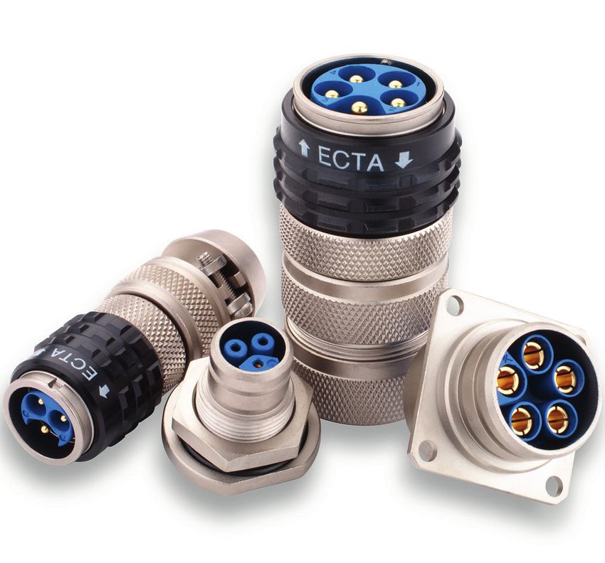
Amphenol

             ECTA 133

             Push-Pull connectors
             Push-Pull Steckverbinder
             Connecteurs Push-Pull

Connectors tested and certified according to EN 61984 per VDE registration number 6908
Steckerbaureihe geprüft und zertifiziert nach DIN EN 61984 unter VDE Reg.Nr. 6908
Connecteurs testés et certifiés selons EN 61984 per VDE N. 6908
Our products are the subject of continuous development and we reserve the right to introduce changes in their design. Wir sind bestrebt, unsere Produkte weiter zu entwickeln und behalten uns maßliche oder technische Änderungen an den Steckverbindungen vor. Les informations contenues dans ce catalogue sont susceptibles d’évoluer.
Summary / Übersicht / Sommaire                                                                                    1

Serie 1331/1332

How to order / Bestellschlüssel / Référence                                                                   2-3

Technical characteristics / Technische Beschreibung / Caractéristiques techniques                                     4

Generalities / Allgemeines / Généralités                                                                      5-6

Arrangements / Polbilder / Arrangements                                                                     7 - 11

Shells / Gehäuse / Boitiers                                                                                12 - 15

Bulkhead / Schottdurchführungen / Traversée de cloison                                                            16

Backshells / Endgehäuse / Raccords                                                                         17 - 19

Accessories / Zubehör / Accessoires                                                                        20 - 21

Polarization / Kodierung / Polarisation                                                                           22

Technical information / Technische Daten / Caractéristiques techniques                                     23 - 24

Special contacts / Sonderkontakte / Contacts spéciaux                                                             25

Overmolded connector and derivation box / Sonderstecker und Verteilerbox / Connecteur cablé et boite de distri.   26

Assembling / Verarbeitung / Procédure de câblage                                                           27 - 29

Guidelines to select a plug connector / Leitfaden zur Auswahl eines Steckverbinders /                      30 - 38
Guide de sélection d'un connecteur
2      How to order / Bestellschlüssel / Référence

         Serie / Baureihe / Série                                        (1) 33      1     E     103      M        Z   2   -
1        Aluminium / Aluminium / Aluminium
2        Brass / Messing / Laiton
6        Stainless Steel / Edelstahl / Inox

1        Power transmission / Netzstecker / Alimentation - VDE & UL listed
2        Signal transmission / Datenübertragungsstecker / Signal - VDE & UL listed

E     Flange receptacle / Flanschsteckdose / Embase
EC    Angular flange receptacle / Flanschsteckdose 90° / Embase 90°
ER    Flange receptacle with backshell connection / Flanschsteckdose mit Endg. Anschluss /
      Embase pour montage d’un raccord
EV    Receptacle, single hole fixing / Steckdose, Einlochmontage / Embase monotrou
EVL   EV with conductive seal / EV mit leitender Dichtung / EV avec joint conducteur
EVR   EV with backshell connection / EV mit Endg. Anschluss / EV avec montage d'un raccord
EVRL EVR with conductive seal / EVR mit leitender Dichtung / EVR avec joint conducteur
EO    Receptacle with oval flange / ovale Steckdose / Embase ovale
M     Plug standard / Stecker standard / Mobile standard
ML    M with conductive seal / M mit leitender Dichtung / M avec joint conducteur
MESV Plug with flange, standard / Stecker mit Flansch, standard / Mobile carré, standard
MESVL MESV with conductive seal / MESV mit leitender Dichtung / MESV avec joint conducteur
P     Inline receptacle / Kabelverlängerung / Prolongateur

103      Serie   X331   (   2   +   PE   13A   )
193      Serie   X331   (   2   +   PE   13A   )
205      Serie   X331   (   4   +   PE   13A   )
295      Serie   X331   (   4   +   PE   13A   )
303      Serie   X331   (   2   +   PE   40A   )
303A     Serie   X331   (   2   +   PE   25A   )
303B     Serie   X331   (   2   +   PE   30A   )
405      Serie   X331   (   4   +   PE   40A   )
405A     Serie   X331   (   4   +   PE   25A   )
405B     Serie   X331   (   4   +   PE   30A   )
410      Serie   X331   (   2   +   PE   40A   )   +   (   7 x 10A )
410A     Serie   X331   (   2   +   PE   25A   )   +   (   7 x 10A )
410B     Serie   X331   (   2   +   PE   30A   )   +   (   7 x 10A )
529      Serie   X331   (   3   +   PE   13A   )   +   (   25 x 10A )

003      Serie   X332   (   3 x 7,5A )
006      Serie   X332   (   6 x 5A )
103      Serie   X332   (   3 x 10A )
107      Serie   X332   (   7 x 7,5A )
204      Serie   X332   (   4 x 25A )
212      Serie   X332   (   12 x 7,5A     )
319      Serie   X332   (   19 x 7,5A     )
426      Serie   X332   (   26 x 7,5A     )
510      Serie   X332   (   10 x 7,5A     )
517      Serie   X332   (   17 x 7,5A     )
518      Serie   X332   (   18 x 7,5A     )
541      Serie   X332   (   41 x 7,5A     )

M        Contact male / Stiftkontakt / Contact mâle
F        Contact female / Buchsenkontakt / Contact femelle

S        Crimp version with machined contacts / Crimp-Ausführung mit gedrehten Kontakten / Version à sertir avec
         contacts décoltés
Y        PCB version with installed machined contacts / PCB-Ausführung mit eingebauten gedrehten Kontakten /
         Version à picot avec contacts décoltés installés
Z        Solder version with installed machined contacts / Löt-Ausführung mit eingebauten gedrehten Kontakten /
         Version à souder avec contacts décoltés installés
X        Without contacts / Ohne Kontakte / Sans contacts
W        With power contacts (no signal contacts) only for arrangements 410-529 / Mit Powerkontakten (ohne
         Signalkontakte) nur bei Polbilder 410-529 / Avec contacts power uniquement (sans contacts signaux)
         pour arrangements 410-529

-        Standard polarization / Standard Kodierung / Polarisation standard
1        Polarization / Kodierung / Polarisation
2        Polarization / Kodierung / Polarisation
3        Polarization / Kodierung / Polarisation
4        Polarization / Kodierung / Polarisation

-        Standard
A        With red locking label / Mit roter Kennzeichnung / Avec marquage rouge de vérrouillage
How to order backshells / Bestellschlüssel Endgehäuse / Référence raccords 3
Ref. (X)330 1 P 2
1 Aluminium / Aluminium / Aluminium
2 Brass / Messing / Laiton
6 Stainless Steel / Edelstahl / Inox
Shell size / Gehäusegröße / Taille du boitier
Backshell type / Endgehäusetyp / Type de raccord
Index for cable diameter / Index für Kabeldurchmesser / Index pour section de câble
Clamping range of the backshells / Klemmbereiche der Endgehäuse / Plages de serrage des raccords
Ø Cable/Kabel/Câble [mm] 2 3 4 5 6 7 8 9 10 11 12 13 14 15 16 17 18 19 20 21 ...25
Size Type Partnum.
Größe Typ Bestelln.
Taille Type Ref.
P (X)3300… P2
0
PEM (X)3300… PEM
P (X)3301… P1 P2 P3
PES (X)3301… PES1 PES2
1 PEM
PEM (X)3301…
DS (1)3301… DS1 DS2 DS3
P (X)3302… P1 P2
P (X)3302… P3
2 PES (X)3302… PES1 PES2
PEM (X)3302… PEM
DS (1)3302… DS2 DS3
P (X)3303… P1 P2
P (X)3303… P3
3
PES (X)3303… PES1
PEM (X)3303… PEM
P (X)3304… P1 P2
PES (X)3304… PES1
4
PEM (X)3304… PEM
DS (1)3304… DS0 DS1 DS2
5 P (X)3305... P0
PEM (X)3305... PEM
For other cable diameters choose backshell PG or PM and attach a standard cable gland.
Andere Kabeldurchmesser können mit PG oder PM Endgehäuse und einer Standardkabelverschraubung realisiert werden.
Pour d'autres sections, utilisez un raccord PG ou PM et un presse-étoupe standard.4 Technical characteristics / Technische Beschreibung / Caractéristiques techniques
Locking system: Push-Pull
Temperature range: - 40°C to +125°c
Mating/unmating operations: 1000 operations for all shell types
IP rating: Up to IP 66/67 (depending on the choice of backshell)
Backshell type P: With complete touch protection. According to DIN EN 61984:
Can be used with both 1331 and 1332 connectors.
Backshell type PEM, DS, CG: Without complete touch protection. According to DIN EN 61984:
PES, PM, PG Can be used with connectors serie 1331.
Can be used with connectors serie 1332 only with installed isolating transformer
and safety extra low voltage (SELV)
Shells material*: Aluminium alloy with a nickel plated finish (locking ring: black anodized), brass nickel-
plated, stainless steel passivated
Contacts material*: Copper alloy with nickel barrier layer and gold plating
Insulator material*: Fiber glass reinforced thermoplast (UL 94-V0, DIN EN 45545-2:2016-02)
Salt spray: 48 hours for Aluminium - 1000 hours for brass and stainless steel
Vibration: DIN EN 60068-2-6 (VDE0468-2-6):2008-10 / 10-2000 Hz / 10g / 10 cycles per axis
Shock: DIN EN 60068-2-27 (VDE0468-2-27):2010-02 / 25g / 6ms / 50 bumps per direction
Standards: DIN EN 61984 Ber 1 (VDE0627 Ber 1):2012-03; UL 1977 on request;
Directive 2002/95/EC - RoHs
Verriegelung: Push-Pull
Zulässige Umgebungstemp. - 40°C bis +125°C
Steckzyklen: 1000 für alle Steckverbinder
Schutzart: bis IP 66/67 (abhängig vom Endgehäuse)
Endgehäuse Typ P: Gehäuse mit vollem Berührungsschutz. Gemäß DIN EN 61984:
Einsetzbar bei Steckern der Serien 1331 und 1332.
Endgehäuse Typ PEM, DS, CG: Gehäuse ohne vollen Berührungsschutz. Gemäß DIN EN 61984:
PES, PM, PG Einsetzbar bei Steckverbindern der Serie 1331.
Einsetzbar bei Steckverbindern der Serie 1332 nur bei vorhandenem Trenntrafo
und Schutzkleinspannung (SELV)
Werkstoff - Gehäuse*: Aluminium Legierung vernickelt (Verriegelungsring eloxiert), Messing vernickelt, Edelstahl passiviert
Werkstoff - Kontakte*: Kupferlegierung vergoldet auf Nickel-Sperrschicht
Werkstoff – Isolierkörper*: Glasfaserverstärktes Thermoplast (UL 94-V0, DIN EN 45545-2:2016-02)
Salzsprühtest: 48 Stunden für Aluminium - 1000 Stunden für Messing und Edelstahl
Vibration: DIN EN 60068-2-6 (VDE0468-2-6):2008-10 / 10-2000Hz / 10g / 10 Zyklen pro Achse
Schock: DIN EN 60068-2-27 (VDE0468-2-27):2010-02 / 25g / 6ms / 50 Shocks pro Richtung
Normen: DIN EN 61984 Ber 1 (VDE0627 Ber 1):2012-03; UL 1977 auf Anfrage;
Richtlinie 2002/95/EC - RoHs
Verrouillage: Push-Pull
Température d’utilisation: - 40°C à +125°C
Cycles d’accouplement : 1000 pour tous les boîtiers
Étanchéité: Jusqu’à IP 66/67 (en fonction du raccord arrière)
Raccords type P: Boîtier entièrement isolé. D’après la norme DIN EN 61984:
Approprié pour les connecteurs séries 1331 et 1332.
Raccords type PEM, DS. CG: Boîtiers isolés partiellement. D’après la norme DIN EN 61984:
PES, PM, PG Appropriés pour les connecteurs série 1331.
Appropriés pour les connecteurs série 1332 uniquement jusqu'à très basse tension de sécurité
(SELV)
Matière – boîtiers*: Alliage d’aluminium nickelé (bague de verrouillage : alliage d’aluminium anodisée), laiton
nickelé, inox passivé
Matière contacts*: Alliage cuivreux avec dorure sur sous-couche nickel.
Matière isolants*: Thermoplastique chargé verre (UL 94-V0, DIN EN 45545-2:2016-02)
Tenue au brouillard salin: 48 heures pour l'aluminium - 1000 heures pour laiton et inox
Vibrations: DIN EN 60068-2-6 (VDE0468-2-6):2008-10 / 10-2000 Hz / 10g / 10 cycles par axe.
Chocs: DIN EN 60068-2-27 (VDE0468-2-27):2010-02 / 25g / 6ms / 50 chocs par direction.
Normes: DIN EN 61984 Ber 1 (VDE0627 Ber 1):2012-03; UL 1977 sur demande;
Directive 2002/95/EC - RoHs
*RoHS and REACH compliant / RoHS und REACH konform / Certifiés RoHS et REACHGeneralities / Allgemeines / Généralités 5
Circular connector series ECTA 133:
This connector was especially designed for industrial applications with its rugged design, convenient push-pull
operation, wide range of contact sizes and high contact density. It provides an ideal component to use in a wide
range of applications:
Typical industrial applications such as robotics and laboratory test equipment, the transportation industry (automobile,
trucks and railway) and tool interconnection.
Serie 1331: power transmission connector (to 125 A rated current) equipped with earth contact linked to the shell -
first make/last break.
Serie 1332: signal transmission connector (25 A) for data or signal as well as power supply for low voltage transmis-
sion.
A fiber optic version is also available (see page 27-28).
Possibility of cabled and overmolded connectors for quantity higher than 500 pieces (see page 38).
Possibility of specific development (for example: mixed arrangement, specific shells…..) for quantity higher than
1000 pieces (on request).
The connectors series ECTA 133 are designed, produced and certified according to EN 61984.
Authoritative for the use of connectors are the respective requirements of the device specifications.
EN61984, Connectors – Safety requirements and tests
This international standard is valid for connectors with and without breaking capacity for ratings from 50V to 1000V
and rated currents up to 125A per contact for which either no type specification exists or which type specification
refers to this norm.
DIN EN 60529 - Degrees of protection provided by enclosures (IP Code)
This defines requirements, and checks for the classification in protection classes, so-called IP-Codes. These specify
the protection against foreign objects and liquids. The protection class is composed of the two letters IP (Ingress
Protection) and 2 digits the first of which defines protection against contact and the second defines protection against
invasion of liquids.
We aim at advancing our products and reserve the right to change measures or technical details.
The technical details given in this catalogue refer to connectors without breaking capacity.
All details concerning IP-Codes are only valid when using the appropriate ECTA133 backshells.
These connectors can’t be connected or disconnected under voltage
Rundsteckverbinder der Serie ECTA 133:
Die Rundsteckverbinder ECTA 133 sind für den Einsatz in der Industrie, im Labor, sowie im Apparate- und Fahrzeug-
bau entwickelt. Sie bewähren sich unter harten Betriebs- und Umgebungsbedingungen. Es handelt sich um wasser-
dichte Steckverbinder mit Push-Pull Schnellverschluss.
Serie 1331: Netzstecker (bis 125 A Nennstrom) mit voreilendem und dem Steckergehäuse leitend verbundenem Mas-
sekontakt.
Serie 1332: Datenübertragungsstecker (25 A) zur Übertragung von Signalen und Daten sowie als Kleinspannungs-
Versorgungsstecker geeignet.
Eine LWL-Ausführung ist ebenfalls lieferbar (siehe Seite 27-28).
Für Mengen größer 500 Stück, besteht die Möglichkeit umspritzte Steckverbindungen zu fertigen (siehe Seite 38).
Für Mengen größer 1000 Stück, ist es möglich Stecker in Sonderausführung (zum Beispiel: Mischpolbild, Gehäuse
in Sonderausführung....) zu entwickeln.
Die Steckverbinder der Baureihe ECTA 133 werden nach EN 61984 konstruiert, gefertigt und geprüft. Verbindlich für
den Einsatz von Steckverbindern sind die jeweiligen Anforderungen der Gerätevorschriften.6 Generalities / Allgemeines / Généralités
EN 61984, Steckverbinder Sicherheitsanforderungen und Prüfungen
Diese internationale Norm gilt für Steckverbinder und Steckvorrichtungen für Bemessungsspannungen von 50V bis
1000V und Bemessungsströme bis 125A je Kontakt, für die es entweder keine Bauartspezifikation gibt, oder wenn
sich deren Bauartspezifikation hinsichtlich der Sicherheitsanforderungen auf die vorliegende Norm bezieht.
DIN EN 60529 - Schutzarten durch Gehäuse (IP-Code)
Die internationale Norm entspricht der deutschen Norm VDE 0470-1. Hierin werden die Anforderungen und Prüfungen
für die Einteilungen in Schutzarten, sogenannte IP-Codes, festgelegt. Diese beschreiben den Schutz gegen feste
Fremdkörper und den Schutz gegen Wasser. Die Schutzart setzt sich immer zusammen aus den beiden Buchstaben
IP (Ingress protection) und 2 Ziffern, wobei die erste Ziffer für den Berührungsschutz und die zweite Ziffer für den
Schutz gegen das Eindringen von Wasser steht.
Wir sind bestrebt unsere Produkte weiterzuentwickeln und behalten uns maßliche und technische Änderungen vor.
Die in diesem Katalog gemachten technischen Angaben beziehen sich auf Steckverbinder, also Bauteile, die nicht
unter Spannung gesteckt oder getrennt werden dürfen.
Angaben zu IP Schutzklassen werden nur unter Verwendung der passenden ECTA 133 Endgehäuse garantiert.
Diese Steckverbinder dürfen betriebsmäßig nicht unter Spannung gesteckt oder getrennt werden.
Connecteur circulaire série ECTA 133:
Les connecteurs circulaires ECTA 133 ont été élaborés pour différents secteurs d’activités tels que l’industrie, la roboti-
que, les laboratoires, les transports, ainsi que tous types d’appareillages pouvant faire appel à la connectique.
Serie 1331: connecteurs d’alimentation (jusqu’à 125 A courant nominal) équipés d’un contact de masse avancé relié
au boîtier.
Serie 1332: connecteurs de transmission de données et de signaux (25 A) ainsi que pour des alimentations de faible
puissance.
Une version fibre optique est également disponible (voir page 27-28).
Possibilité de version surmoulée pour des quantités supérieures à 500 pièces (voir page 38).
Pour des quantités supérieures à 1000 pièces, possibilité de développement de connecteurs spécifiques
(exemple: arrangement mixte, boîtiers spécifiques…).
Les connecteurs ECTA répondent à la norme EN61984 . Pour l'utilisation il est nécessaire de se référer aux normes
spécifiques d´application.
EN61984, norme de sécurité et de test.
Cette norme internationale est applicable pour des connecteurs d´une tension d´utilisation de 50V à 1000V et de cou-
rant par contact allant jusqu´à 125A.
DIN EN 60529 - Norme de protection Code IP
Cette norme définit le degré de protection selon des codes IP suivis de deux chiffres.
Le premier chiffre indique le degré de protection contre les contacts fortuits et la pénétration contre les corps étrangers
solides. Le second chiffre indique le degré de protection contre les effets nuisibles dus à la pénétration de l'eau.
Cette gamme de produits étant susceptible d´évoluer, cela implique donc que les informations contenues dans ce
catalogue ne sont pas contractuelles.
Les connecteurs présentés dans ce catalogue ne peuvent être accouplés/désaccouplés sous charge.
Ils doivent être manœuvrés hors tension. Les caractéristiques techniques présentées se réfèrent à des connecteurs qui
ne peuvent pas être accouplés/désaccouplés sous charge.
Les indices de protection sont uniquement garantis avec le raccord arrière adéquat.
Ces connecteurs ne doivent en aucun cas être couplés ou découplés sous tension.Arrangements / Polbilder / Arrangements 7
All figures are valid for machined contacts / Alle Angaben gelten für gedrehte Kontakte / Données valables pour contacts décoltés
SERIE 1331
Power transmission
Netzstecker
Alimentation
Shell size / Contact arrangement
Gehäusegröße / Polbild 1-03(*) 1-93(*) 2-05(*) 2-95(*) 3-03 3-03A 3-03B
Taille de boitier / Arrangement
Max. current / Contact at 40°C
2 + PE 2 + PE 2 + PE
Max. Strom / Kontakt bei 40°C 2 + PE 13 A 2 + PE 13 A 4 + PE 13 A 4 + PE 13 A
40 A 25 A 30 A
Intensité max. / Contact à 40°C
Contact type
Kontaktanschlussart Y-Z S-Z Y-Z S-Z S-Y-Z
Type de raccordement du contact
Ø Contact [mm]
Ø Kontakt [mm] 2 1,6 2 1,6 3
Ø Contact [mm]
Ø Area [mm]
Ø Anschlussbereich [mm] 2,3 1,6 2,3 1,6 3,3 2 2,6
Ø Zone de connection [mm]
Wire size [mm²]
Anschlussquerschnitt [mm²] 1,5 - 2,5 0,75 - 1,5 1,5 - 2,5 0,75 - 1,5 6 2,5 4
Section admissible [mm²]
Conductor length to be stripped [mm]
Abisolierlänge des Leiters [mm] 6 6 6 6 7
Longueur de dénudage [mm]
Rated voltage (~/-) / See page 25
Nennspannung (~/-) / Siehe Seite 25 1000 V 800 V 800 V 800 V 1000 V
Tension nominale (~/-) / Voir page 25
Rated impulse voltage
Bemessungsstoßspannung 4000 V 4000 V 4000 V 4000 V 4000 V
Tension de choc mesurée
Replacement crimp contacts 133009__
1330 16F 1330 16F
Ersatzcrimpkontakt - - F F1 F2
1330 16M 1330 16M
Contact de sertissage substitut M M1 M2
Replacement mass contact 133009__
1330 16F 1330 16F
Ersatzmassekontakt - - FM FM1 FM2
1330 16M 1330 16M
Contact masse substitut MM MM1 MM2
Stamped/rolled contacts
Gestanzt-gerollte Kontakte - - - - - - -
Contacts découpés roulés
Insert / extraction tool
Ein-/ Ausbauwerkzeug - 1330 OD 16 - 1330 OD 16 1330 OU 10
Outil d'extraction
Crimp plier
Crimpzange - 1330 OP 01 - 1330 OP 01 1330 OP 02
Pince de sertissage
Positioner
1330 1330 1330
Crimpaufsatz - 1330 OS 01 - 1330 OS 01
OS16 OS17 OS18
Jeu de mors
(*) Arrangement 1-03 and 1-93 as well as 2-05 and 2-95 are not compatible
(*) Polbild 1-03 und 1-93, sowie 2-05 und 2-95 sind nicht steckkompatibel
(*) Arrangements 1-03 et 1-93, 2-05 et 2-95 non intermariables
Note / Hinweis / Remarque:
For drilling plans (for PCB-Version), please look at our website: www.amphenol-airlb.de
Bohrpläne (für PCB-Version) finden Sie auf unserer Homepage: www.amphenol-airlb.de
Plans de perçage (pour version PCB) disponibles sur notre site: www.amphenol-airlb.de.8 Arrangements / Polbilder / Arrangements
All figures are valid for machined contacts / Alle Angaben gelten für gedrehte Kontakte / Données valables pour contacts décoltés
SERIE 1331
Power transmission
Netzstecker
Alimentation
Shell size / Contact arrangement
Gehäusegröße / Polbild 4-05 4-05A 4-05B 4-10(4) 4-10A 4-10B 5-29
Taille de boitier / Arrangement
Max. current / Contact at 40°C 2 + PE 2 + PE 2 + PE
4+ PE 4+ PE 4+ PE 3 + PE 13A
Max. Strom / Kontakt bei 40°C 40A 25A 30A
40A 25A 30A 25 x 10A
Intensité max. / Contact à 40°C 7x7,5A 7x7,5A 7x7,5A
Contact type
Kontaktanschlussart S-Y-Z S S
Type de raccordement du contact
Ø Contact [mm]
3x3 4 x 1,6
Ø Kontakt [mm] 5x3
7x1 25 x 1
Ø Contact [mm]
Ø Area [mm] 3,3 2 2,6 1,6
Ø Anschlussbereich [mm] 3,3 2 2,6
1,1 1,1
Ø Zone de connection [mm]
Wire size [mm²] 6 2,5 4 1,5
Anschlussquerschnitt [mm²] 6 2,5 4
0,25 - 1 0,25 - 1
Section admissible [mm²]
Conductor length to be stripped [mm]
3 x 7,5 4x6
Abisolierlänge des Leiters [mm] 7,5
7x4 25 x 4
Longueur de dénudage [mm]
Rated voltage (~/-) / See page 25
2 x 1000 V 3 x 800 V
Nennspannung (~/-) / Siehe Seite 25 1000 V
7 x 630 V 25 x 630 V
Tension nominale (~/-) / Voir page 25
Rated impulse voltage
4000 V 4000 V
Bemessungsstoßspannung 4000 V
2500 V 2500 V
Tension de choc mesurée
Replacement crimp contact 133009__ 133009__
1330 16 F
Ersatzcrimpkontakt F F1 F2 F F1 F2 1330 16 M
Contact de sertissage substitut M M1 M2 M M1 M2
Replacement signal contact 5440 020 F
Ersatzsignalkontakt -
Contact signal substitut 5440 020 M
Replacement mass contact 133009__ 133009__
1330 16 F
Ersatzmassekontakt FM FM1 FM2 FM FM1 FM2
Contact masse substitut 1330 16 M
MM MM1 MM2 MM MM1 MM2
Stamped rolled contacts (1)(2) 1330 20 FR100
Gestanzt-gerollte Kontakte (1)(2) - - - 1330 20 MR100
Contacts découpés-roulés (1)(2) Reel of 10.000pcs
Insert / extraction tool 1330 OD 20S 1330 OD 20S
Ein-/ Ausbauwerkzeug 1330 OU 10
Outil d'extraction 1330 OU 10 1330 OD 16
Crimp plier
Crimpzange 1330 OP 02 1330 OP 02 1330 OP 01
Pince de sertissage
Positioner 1330 1330 1330
1330 1330 1330
Crimpaufsatz 1330 OS 01
OS16 OS17 OS18 OS16 OS17 OS18
Jeu de mors
Crimp plier for signal contacts
Crimpzange für Signalkontakte - - - 5440 OP 04
Pince de sertissage pour c. de sign.
Positioner for signal contacts
Crimpaufsatz für Signalkontakte - - - 5440 OS 15
Jeu de mors pour contacts signaux
(1) Stamped rolled contacts for 410-529 : The plug must be ordered in version W and signal contacts must be ordered separatly.
Gestanzt-gerollte Kontakte für 410-529 : Stecker in Ausführung W bestellen und Signalkontakte getrennt bestellen.
Contacts découpés-roulés pour 410-529 : Le connecteur doit être commandé en version W et les contacts signaux doivent être commandés
séparément.
(2) For max. 5A / Für max. 5A / Pour max. 5A
(3) Crimping tool coax / Crimpwerkzeug Coax / Outil de sertissage coax: 1330 OP 11
(4) The power contact cannot be removed after cabling / Der Power-Kontakt ist nach der Verkabelung nicht mehr ausbaubar / Le contact power n'est
plus démontable après le câblageArrangements / Polbilder / Arrangements 9
All figures are valid for machined contacts / Alle Angaben gelten für gedrehte Kontakte / Données valables pour contacts décoltés
SERIE 1332
Signal transmission
Datenübertragung
Signal
Shell size / Contact arrangement
Gehäusegröße / Polbild 0-03 0-06 1-03 1-07 2-04 2-12
Taille de boitier / Arrangement
Max. current / Contact at 40°C
Max. Strom / Kontakt bei 40°C 3 x 7,5 A 6x5A 3 x 13 A 7 x 7,5 A 4 x 25 A 12 x 7,5 A
Intensité max. / Contact à 40°C
Contact type
Kontaktanschlussart S-Y-Z S-Z Z S-Y-Z S-Z S-Y-Z
Type de raccordement du contact
Ø Contact [mm]
Ø Kontakt [mm] 1,3 0,8 2 1,3 3 1,3
Ø Contact [mm]
Ø Area [mm]
Ø Anschlussbereich [mm] 1,3 0,8 2,1 1,3 2,5 1,2
Ø Zone de connection [mm]
Wire size [mm²]
Anschlussquerschnitt [mm²] 0,34 - 1 0,10 - 0,34 2,5 0,34 - 1 4 0,34 - 1
Section admissible [mm²]
Conductor length to be stripped [mm]
Abisolierlänge des Leiters [mm] 4 3,5 5 4 6,5 4
Longueur de dénudage [mm]
Rated voltage (~/-) / See page 25
Nennspannung (~/-) / Siehe Seite 25 250 V 200 V 400 V 320 V 400 V 320 V
Tension nominale (~/-) / Voir page 25
Rated impulse voltage
Bemessungsstoßspannung 1500 V 800 V 1500 V 1500 V 1500 V 1500 V
Tension de choc mesurée
Replacement crimp contact
1330 20 F 1330 22 F 1330 20 F 1330 11 F 1330 20 F
Ersatzcrimpkontakt -
1330 20 M 1330 22 M 1330 20 M 1330 11 M 1330 20 M
Contact de sertissage substitut
Stamped/rolled contacts possible
Gestanzt-gerollte Kontakte möglich - - - - - -
Contacts découpés roulés possibles
Insert / extraction tool
Ein-/ Ausbauwerkzeug 1330 OD 20 1330 OD 22 - 1330 OD 20 1330 OU 14 1330 OD 20
Outil d'extraction
Crimp plier
Crimpzange 1330 OP 01 1330 OP 04 - 1330 OP 01 1330 OP 02 1330 OP 01
Pince de sertissage
Positioner
M: 1330 OS 14
Crimpaufsatz 1330 OS 01 - 1330 OS 01 1330 OS 11 1330 OS 01
F. 1330 OS 13
Jeu de mors
Thermocontact possible (1)
Thermokontakt möglich (1) 4 - - 4 - 4
Thermocontact possible (1)
For 100.000 mating cycles (1)
Für 100.000 Steckzyklen (1) 4 4 - 4 - 4
Pour 100.000 cycles de manoeuvre (1)
(1) See page 26 / Siehe Seite 26 / Voir page 2610 Arrangements / Polbilder / Arrangements
All figures are valid for machined contacts / Alle Angaben gelten für gedrehte Kontakte / Données valables pour contacts décoltés
SERIE 1332
Signal transmission
Datenübertragung
Signal
Shell size / Contact arrangement
Gehäusegröße / Polbild 3-19 4-26 5-10 5-17
Taille de boitier / Arrangement
Max. current / Contact at 40°C
Max. Strom / Kontakt bei 40°C 19 x 7,5 A 26 x 7,5 A 10 x 7,5 A 17 x 7,5 A
Intensité max. / Contact à 40°C
Contact type
Kontaktanschlussart S-Y-Z S-Y-Z S-Y S-Y
Type de raccordement du contact
Ø Contact [mm]
Ø Kontakt [mm] 1,3 1,3 1,0 1,0
Ø Contact [mm]
Ø Area [mm]
Ø Anschlussbereich [mm] 1,2 1,2 1,2 1,2
Ø Zone de connection [mm]
Wire size [mm²]
Anschlussquerschnitt [mm²] 0,34 - 1 0,34 - 1 0,25 - 1 0,25 - 1
Section admissible [mm²]
Conductor length to be stripped [mm]
Abisolierlänge des Leiters [mm] 4 4 4 4
Longueur de dénudage [mm]
Rated voltage (~/-) / See page 25
Nennspannung (~/-) / Siehe Seite 25 250 V 250 V 250 V 250 V
Tension nominale (~/-) / Voir page 25
Rated impulse voltage
Bemessungsstoßspannung 800 V 800 V 1500 V 1500 V
Tension de choc mesurée
Replacement crimp contact
1330 20 F 1330 20 F 5440 020 F 5440 020 F
Ersatzcrimpkontakt
1330 20 M 1330 20 M 5440 020 M 5440 020 M
Contact de sertissage substitut
Stamped rolled contacts possible (1)
1330 20 FR100 1330 20 FR100
Gestanzt-gerollte Kontakte möglich (1) - -
1330 20 MR100 1330 20 MR100
Contacts découpés-roulés possibles(1)
Insert / extraction tool
Ein-/ Ausbauwerkzeug 1330 OD 20 1330 OD 20 1330 OD 20S 1330 OD 20S
Outil d'extraction
Crimp plier
Crimpzange 1330 OP 01 1330 OP 01 1330 OP 01 5440 OP 04
Pince de sertissage
Positioner
5440 OS 15
Crimpaufsatz 1330 OS 01 1330 OS 01 1330 OS 01
(M22520/1-02)
Jeu de mors
Thermocontact possible (2)
Thermokontakt möglich (2) 4 4 - -
Thermocontact possible (2)
For 100.000 mating cycles (2)
Für 100.000 Steckzyklen (2) 4 4 4 4
Pour 100.000 cycles de manoeuvre (2)
(1) Stamped rolled contacts for 510 - 517 : The plug must be ordered in version W and signal contacts must be ordered separatly.
Gestanzt-gerollte Kontakte für 510 - 517: Stecker in Ausführung W bestellen und Signalkontakte getrennt bestellen.
Contacts découpés-roulés pour 510 - 517: Le connecteur doit être commandé en version W et les contacts signaux doivent être commandés
séparément.
(2) See page 26 / Siehe Seite 26 / Voir page 26Arrangements / Polbilder / Arrangements 11
All figures are valid for machined contacts / Alle Angaben gelten für gedrehte Kontakte / Données valables pour contacts décoltés
SERIE 1332
Signal transmission
Datenübertragung
Signal
Shell size / Contact arrangement
Gehäusegröße / Polbild 5-18 5-41
Taille de boitier / Arrangement
Max. current / Contact at 40°C
Max. Strom / Kontakt bei 40°C 18 x 7,5 A 41 x 7,5 A
Intensité max. / Contact à 40°C
Contact type
Kontaktanschlussart S-Y S-Y
Type de raccordement du contact
Ø Contact [mm]
Ø Kontakt [mm] 1,0 1,0
Ø Contact [mm]
Ø Area [mm]
Ø Anschlussbereich [mm] 1,2 1,2
Ø Zone de connection [mm]
Wire size [mm²]
Anschlussquerschnitt [mm²] 0,25 - 1 0,25 - 1
Section admissible [mm²]
Conductor length to be stripped [mm]
Abisolierlänge des Leiters [mm] 4 4
Longueur de dénudage [mm]
Rated voltage (~/-) / See page 25
Nennspannung (~/-) / Siehe Seite 25 250 V 250 V
Tension nominale (~/-) / Voir page 25
Rated impulse voltage
Bemessungsstoßspannung 1500 V 1500 V
Tension de choc mesurée
Replacement crimp contact
5440 020 F 5440 020 F
Ersatzcrimpkontakt
5440 020 M 5440 020 M
Contact de sertissage substitut
Stamped rolled contacts (1)(2)
1330 20 FR100
Gestanzt-gerollte Kontakte (1)(2)
1330 20 MR100
Contacts découpés-roulés (1)(2)
Insert / extraction tool
Ein-/ Ausbauwerkzeug 1330 OD 20S 1330 OD 20S
Outil d'extraction
Crimp plier
Crimpzange 5440 OP 04 5440 OP 04
Pince de sertissage
Positioner
Crimpaufsatz 5440 OS 15 5440 OS 15
Jeu de mors
Thermocontact possible
Thermokontakt möglich - -
Thermocontact possible
For high mating cycles
Für hohe Steckzyklen 4 4
Pour des cycles de manoeuvre élevés
(1) Stamped rolled contacts for 518 - 541 : The plug must be ordered in version W and signal contacts must be ordered separatly.
Gestanzt-gerollte Kontakte für 518 - 541: Stecker in Ausführung W bestellen und Signalkontakte getrennt bestellen.
Contacts découpés-roulés pour 518 - 541: Le connecteur doit être commandé en version W et les contacts signaux doivent être commandés
séparément.
(2) See page 26 / Siehe Seite 26 / Voir page 2612 Shells / Gehäuse / Boitiers
Version available / Lieferbare Ausführung / Version disponible : (1)33: Aluminium / Aluminium / Aluminium
Versions on request / Ausführungen auf Anfrage / Versions sur demande: (2)33: Brass / Messing / Laiton
(6)33: Stainless Steel / Edelstahl / Inox
M*/ ML*
(ML with conductive silicone seal / ML mit leitender Silikon-
dichtung / ML avec joint conducteur en silicone)
Plug
Stecker
Mobile
Shell/Gehäuse/Boitier 0 1 2 3 4 5 6 7
ØJ 17 22 26 29 32,5 37,5 54 67
ØK 15 20 24 26 30,5 36 49,8 56,2
L 29 29 29 30 30 32 49,5 76
Attenuation Curve: see page 24 / Dämpfungskennlinie: siehe Seite 24 / Courbe d’atténuation: voir page 24
MESV / MESVL
(MESVL with conductive silicone seal / MESVL mit leitender Silikon-
dichtung / MESVL avec joint conducteur en silicone)
Plug with flange for front panel mounting
Stecker mit Vierkantflansch für Vorderwandmontage
Mobile carré pour montage face avant
Mates with inline receptacle P / Steckbar mit Kabelsteckdose P / Peut-être assemblé avec un prolongateur P
Shell/Gehäuse/Boitier 0 1 2 3 4 5 6 7
ØA - - - - 28 31,4 - -
B - - - - 37 37 - -
ØC - - - - 3,5 3,5* - -
D - - - - 29 29 - -
L - - - - 29 29 - -
*Bevelled screw / *Senkschraube / *Vis Chanfreinée
Attenuation Curve: see page 24 / Dämpfungskennlinie: siehe Seite 24 / Courbe d’atténuation: voir page 24
E
Receptacle with flange
Flanschsteckdose
Embase
Front & back panel mounting (Wall thickness, see measures H)
Vorderwand- und Hinterwandmontage (Wandstärke, siehe Maß H)
Montage face avant et face arrière (Épaisseur de paroi, voir ligne H).
Shell/Gehäuse/Boitier 0 1 2 3(°) 3 4(°) 4 5 6 7
A 12,7 18 21 23 23 24,8 24,8 29 38 47-49
B 18 24 27 29 29 31 31 37 47 62
ØC 3,2 3,5 3,5 3,5 3,5 3,5 3,5 3,5 4,5 5,5
D (max.) 8,6 13,2 13,2 6,5 15 7,5 15 13,5 20 40
F 4,8 5,6 5,6 5,1 10,8 5,1 10,8 8,4 20 40
G 1,5 1,6 1,6 1,5 1,5 1,5 1,5 2,7 2,5 4
H (max.) 3 3 3 3 3 3 3 3 5,5 11,8
ØK 12,5 18,5 23,5 23,5 23,5 26,5 26,5 32 42,5 54,5
L 10,5 10,5 10,5 10,5 10,5 10,5 10,5 10,5 26 35
(°) Receptacle used only for serie 1332 in solder version / Wird nur für Baureihe 1332 in Lötausführung benutzt / Utilisée uniquement pour la
série 1332 en version à souder.
* For the shells ER, EVR/EVRL, M, and P the assembly of a backshell is necessary to hold the insulator in position.
* Bei den Gehäusen ER, EVR/EVRL, M und P ist die Montage eines Endgehäuses erforderlich um den Isolierkörper festzuhalten.
* Pour les boitiers ER, EVR/EVRL, M et P le montage d’un raccord est nécessaire pour le maintien de l’isolant.Shells / Gehäuse / Boitiers 13
Version available / Lieferbare Ausführung / Version disponible : (1)33: Aluminium / Aluminium / Aluminium
Versions on request / Ausführungen auf Anfrage / Versions sur demande: (2)33: Brass / Messing / Laiton
(6)33: Stainless Steel / Edelstahl / Inox
EO
Receptacle with oval flange
Steckdose mit ovalem Flansch
Embase ovale
Front & back panel mounting (Wall thickness, see measures H
Vorderwand- und Hinterwandmontage (Wandstärke, siehe Maß H)
Montage face avant et face arrière (Épaisseur de paroi, voir ligne H).
Other sizes upon request / andere Größen auf Anfrage / autres dimensions sur demande
Shell/Gehäuse/Boitier 0 1 2 3 4 5 6 7
L - - 27 27 - - - -
L1 - - 26 23 - - - -
L2 - - 20 23 - - - -
L3 - - 13 14 - - - -
L4 - - 2 2 - - - -
ØA - - 18 19 - - - -
ØB - - 23 23 - - - -
ØC - - 4,5 4,5 - - - -
H (max.) - - 2,5 3 - - - -
ER*
Receptacle with flange and thread for backshell assembly
Flanschsteckdose mit Gewinde zur Montage eines Endgehäuses
Embase permettant le montage d’un raccord
Front & back panel mounting (Wall thickness, see measures H)
Vorderwand- und Hinterwandmontage (Wandstärke, siehe Maß H)
Montage face avant et face arrière (Épaisseur de paroi, voir ligne H)
Shell/Gehäuse/Boitier 0 1 2 3 4 5 6 7
A 16 18 21 23 24,8 - 38 47-49
B 22 24 27 29 31 - 47 62
ØC 3,2 3,5 3,5 3,5 3,5 - 4,5 5,5
D 16,5 13,8 13,8 16,5 16,5 - 15 40
G 1,5 1,5 1,5 1,5 1,5 - 2,5 4
H (max.) 2,4 3,4 3,4 3,4 3,4 - 5,5 11,8
ØK 15,1 20 24 26 30,5 - 42,5 54,5
L 10,1 10,1 10,1 10,1 10,1 - 26 35
* For the shells ER, EVR/EVRL, M, and P the assembly of a backshell is necessary to hold the insulator in position.
* Bei den Gehäusen ER, EVR/EVRL, M und P ist die Montage eines Endgehäuses erforderlich um den Isolierkörper festzuhalten.
* Pour les boitiers ER, EVR/EVRL, M et P le montage d’un raccord est nécessaire pour le maintien de l’isolant.14 Shells / Gehäuse / Boitiers
Version available / Lieferbare Ausführung / Version disponible : (1)33: Aluminium / Aluminium / Aluminium
Versions on request / Ausführungen auf Anfrage / Versions sur demande: (2)33: Brass / Messing / Laiton
(6)33: Stainless Steel / Edelstahl / Inox
EV / EVL
(EVL with conductive silicone O-Ring seal /
EVL mit leitender Silikon-O-Ring Dichtung /
EVL avec joint torique conducteur en silicone)
Receptacle for back panel single hole fixing
(fixing with nut and with O-Ring seal)
Steckdose für Hinterwand- Einlochbefestigung
(mit Gegenmutter und O-Ring Dichtung)
Embase monotrou (fixation avec écrou
pour montage face arrière et joint torique)
(Wall thickness, see measures C / Wandstärke, siehe Maß C / Épaisseur de paroi, voir ligne C)
Shell/Gehäuse/Boitier 0 1 2 3 4 5 6 7
A 24 24 24 - 29,7 - - -
B 3,5 3,5 3,5 - 3,5 - - -
D 4 4 4 - 4 - - -
F 21 24 30 - 34 - - -
ØG 24,5 27,5 33,5 - 37,5 - - -
H 19 22 26 - 32 - - -
J 13,5 16,5 20,5 - 24,5 - - -
ØK 14 17 21 - 25 - - -
L 10,5 10,5 10,5 - 10,5 - - -
C (max.) 6 6 6 - 11,7 - - -
EVR* / EVRL*
(EVRL with conductive silicone O-Ring seal /
EVRL mit leitender Silikon-O-Ring Dichtung /
EVRL avec joint torique conducteur en silicone)
Receptacle for back panel single hole fixing with
flange and thread for backshell assembly
Steckdose für Hinterwand- Einlochbefestigung
mit Gewinde zur Montage eines Endgehäuses
Embase (fixation avec écrou pour montage face arrière)
permettant le montage d'un raccord
(Wall thickness, see measures C / Wandstärke, siehe Maß C / Épaisseur de paroi, voir ligne C)
Shell/Gehäuse/Boitier 0 1 2 3 4 5 6 7
A - 28,8 28,8 31,5 38,1 33,4 - -
B - 3,5 3,5 3,5 3,5 3,5 - -
D - 4 4 4 4 4 - -
F - 26 30 34 36 42 - -
ØG - 28 33,5 38 38 44 - -
H - 22 26 32 32 40 - -
J - 17,5 21,5 23,5 27 34 - -
ØK - 18 22 24 27,5 35 - -
L - 10,5 10,5 10,5 10,5 10,5 - -
M - 8,3 8,3 8 11,1 9,9 - -
C (max.) - 6 6 9 12,5 9 - -
* For the shells ER, EVR/EVRL, M, and P the assembly of a backshell is necessary to hold the insulator in position.
* Bei den Gehäusen ER, EVR/EVRL, M und P ist die Montage eines Endgehäuses erforderlich um den Isolierkörper festzuhalten.
* Pour les boitiers ER, EVR/EVRL, M et P le montage d’un raccord est nécessaire pour le maintien de l’isolant.Shells / Gehäuse / Boitiers 15
Version available / Lieferbare Ausführung / Version disponible : (1)33: Aluminium / Aluminium / Aluminium
Versions on request / Ausführungen auf Anfrage / Versions sur demande: (2)33: Brass / Messing / Laiton
(6)33: Stainless Steel / Edelstahl / Inox
P*
Cable receptacle
Kabelverlängerung
Prolongateur
Shell/Gehäuse/Boitier 0 1 2 3 4 5 6 7
ØK 15 20 24 26 30,5 36 - -
L 10,5 10,5 10,5 10,5 10,5 10,5 - -
M 20 18,3 18,3 21 21 21,8 - -
EC
Receptacle with angular shell
Flanschsteckdose 90°
Embase coudée 90°
Only in Aluminium / nur in Aluminium / uniquement en aluminium
Shell/Gehäuse/Boitier 0 1 2 3 4 5 6 7
A - - 64 60,7 - - - -
B - - 29 29 - - - -
C - - 2 2 - - - -
D - - 36 32,7 - - - -
E - - 27 27 - - - -
F - - 15 15 - - - -
H - - 5 5 - - - -
I - - 7,5 7,5 - - - -
J - - 14,5 14,5 - - - -
K - - 23 23 - - - -
L - - 29 29 - - - -
M - - 15,5 15,5 - - - -
Other sizes upon request / andere Größen auf Anfrage / autres dimensions sur demande
* For the shells ER, EVR/EVRL, M, and P the assembly of a backshell is necessary to hold the insulator in position.
* Bei den Gehäusen ER, EVR/EVRL, M und P ist die Montage eines Endgehäuses erforderlich um den Isolierkörper festzuhalten.
* Pour les boitiers ER, EVR/EVRL, M et P le montage d’un raccord est nécessaire pour le maintien de l’isolant.16 Bulkhead / Schottdurchführungen / Traversée de cloison
Version available / Lieferbare Ausführung / Version disponible : (1)33: Aluminium / Aluminium / Aluminium
Versions on request / Ausführungen auf Anfrage / Versions sur demande: (2)33: Brass / Messing / Laiton
(6)33: Stainless Steel / Edelstahl / Inox
Bulkhead for back panel single hole fixing (fixing with nut and with O-Ring seal) for pressure differentials up to 5 bar.
Schottdurchführung für Hinterwand- Einlochbefestigung (mit Gegenmutter und O-Ring Dichtung) für Anwendungen bis 5 Bar Druck-
differenzen.
Traversée de cloison (fixation avec écrou pour montage face arrière et joint torique) pour des différentiels de pression jusqu’ à 5 bar.
S.1g fS.2
(Wall thickness, see measures E / Wandstärke, siehe Maß E / Épaisseur de paroi, voir ligne E)
Arrangement E
Ref. Polbild S.1 S.2 A B C D F G H
Arrangement (max.)
(X)331 EE 103 FM F M
1-03 40 3,5 10,5 4 26 29 M 21 x 1 11,5
(X)331 EE 103 MF M F
(X)331 EE 205 FM F M
2-05 40 3,5 10,5 4 32 36 M 25 x 1 11,5
(X)331 EE 205 MF M F
(X)331 EE 303 FM F M
3-03 40 3,5 10,5 4 38 40 M 29 x 1 11,5
(X)331 EE 303 MF M F
(X)331 EE 405 FM F M
4-05 40 3,5 10,5 4 46 50 M 36 x 1 11,5
(X)331 EE 405 MF M F
(X)332 EE 003 FM F M
0-03 40 3,5 10,5 4 22 24 M 17 x 1 11,5
(X)332 EE 003 MF M F
(X)332 EE 107 FM F M
1-07 40 3,5 10,5 4 26 29 M 21 x 1 11,5
(X)332 EE 107 MF M F
(X)332 EE 212 FM F M
2-12 40 3,5 10,5 4 32 36 M 25 x 1 11,5
(X)332 EE 212 MF M F
(X)332 EE 319 FM F M
3-19 40 3,5 10,5 4 38 40 M 29 x 1 11,5
(X)332 EE 319 MF M F
(X)332 EE 426 FM F M
4-26 40 3,5 10,5 4 46 50 M 36 x 1 11,5
(X)332 EE 426 MF M F
(X)332 EE 541 FM F M
5-41 40 3,5 10,5 4 50 55 M 40 x 1 11,5
(X)332 EE 541 MF M F
Leak rate is a maximum of 1 x 10⁻⁷ cm3/S for 1 bar difference.
Leckrate ist max 1 x 10⁻⁷ cm3/S bei 1 bar.
Le taux de fuite est au maximum 1 x 10⁻⁷ cm3/S pour 1 bar.Backshells / Endgehäuse / Raccords 17
Version available / Lieferbare Ausführung / Version disponible : (1)33: Aluminium / Aluminium / Aluminium
Versions on request / Ausführungen auf Anfrage / Versions sur demande: (2)33: Brass / Messing / Laiton
(6)33: Stainless Steel / Edelstahl / Inox
P A:
Backshell IP67
(the types A or B are dependent on the cable Ø).
Endgehäuse IP67
(Typ A oder B abhängig vom Kabeldurchmesser Ø).
Raccord IP67
(les types A et B sont dépendants du Ø du câble).
B:
(In accordance to EN61984 - See page 4 / Nach EN61984 - Siehe Seite 4 / En accordance avec l' EN61984 - Voir page 4)
Ref. Shell/Gehäuse/Boitier A/B M ØN Cable/Kabel/Câble ØP[mm]
(X)330 0 P2 0 A 13 14 4,5 - 6
(X)330 1 P1 1 A 21,5 18 5 - 6,5
(X)330 1 P2 1 A 21,5 18 6,5 - 9
(X)330 1 P3 1 B 43 22 9 - 12,5
(X)330 2 P1 2 A 22,5 22 8 - 10
(X)330 2 P2 2 A 22,5 22 10 - 13,5
(X)330 2 P3 2 B 46 25 11,5 - 14,5
(X)330 3 P1 3 A 31 25 10,5 - 12,5
(X)330 3 P2 3 B 51 28 12,5 - 15
(X)330 3 P3 3 B 51 28 15 - 18
(X)330 4 P1 4 B 54 31 15 - 18
(X)330 4 P2 4 B 54 31 18 - 21
(X)330 5 P0 5 B 50,5 37 18 - 25
PES
Backshell IP67 with braid clamping
Endgehäuse IP67 für Schirmanbindung
Raccord IP67 avec raccordement de blindage
(In accordance to EN61984 - See page 4 / Nach EN61984 - Siehe Seite 4 / En accordance avec l' EN61984 - Voir page 4)
Ref. Shell/Gehäuse/Boitier M ØN Cable/Kabel/Câble ØP [mm]
(X)330 1 PES 1 1 42 24 5,5 - 9
(X)330 1 PES 2 1 42 24 9 - 12
(X)330 2 PES 1 2 42 24 5,5 - 9
(X)330 2 PES 2 2 42 24 9 - 12
(X)330 3 PES 1 3 45 30 13 - 18
(X)330 4 PES 1 4 45 30 13 - 18
PEM
Backshell IP67 with braid clamping
Endgehäuse IP67 für Schirmanbindung
Raccord IP67 avec raccordement de blindage
(In accordance to EN61984 - See page 4 / Nach EN61984 - Siehe Seite 4 / En accordance avec l' EN61984 - Voir page 4)
Ref. Shell/Gehäuse/Boitier M ØN Cable/Kabel/Câble ØP [mm]
(X)330 0 PEM 0 22 15 2,5 - 5
(X)330 1 PEM 1 28 24 8 - 13
(X)330 2 PEM 2 28 24 8 - 13
(X)330 3 PEM 3 33 30 13 - 18
(X)330 4 PEM 4 33 30 13 - 18
(X)330 5 PEM 5 33 40 18 - 2518 Backshells / Endgehäuse / Raccords
Version available / Lieferbare Ausführung / Version disponible : (1)33: Aluminium / Aluminium / Aluminium
Versions on request / Ausführungen auf Anfrage / Versions sur demande: (2)33: Brass / Messing / Laiton
(6)33: Stainless Steel / Edelstahl / Inox
PM / PG
Adaptor with metric or PG thread
Adapter mit metrischem oder PG Innengewinde
Raccord intermédiaire avec filetage métrique ou PG
(In accordance to EN61984 - See page 4 / Nach EN61984 - Siehe Seite 4 / En accordance avec l' EN61984 - Voir page 4)
Ref. Ref. PG Shell/Gehäuse/Boitier A (PM) A (PG) B ØC D
(X)330 0 PM 12 (X)330 0 PG 7 0 M12 x 1,5 PG 7 14 15 5
(X)330 1 PM 16 (X)330 1 PG 11 1 M16 x 1,5 PG 11 20 21 6
(X)330 1 PM 20 - 1 M20 x 1,5 - 20 24,7 6
(X)330 2 PM 16 (X)330 2 PG 11 2 M16 x 1,5 PG 11 20 24 6
(X)330 2 PM 20 (X)330 2 PG 13 2 M20 x 1,5 PG 13 20 25 6
(X)330 3 PM 20 (X)330 3 PG 11 3 M20 x 1,5 PG 11 20 26 6
(X)330 3 PM 25 (X)330 3 PG 13 3 M25 x 1,5 PG 13 20 30,7 7
(X)330 4 PM 20 (X)330 4 PG 16 4 M20 x 1,5 PG 16 20 30 6
(X)330 4 PM 25 - 4 M25 x 1,5 - 20 30,7 7
(X)330 5 PM 25 (X)330 5 PG 21 5 M25 x 1,5 PG 21 20 35 7
(X)330 6 PM 32 (X)330 6 PG 29 6 M32 x 1,5 PG 29 35 50 8
(X)330 7 PM 50 (X)330 7 PG 36 7 M50 x 1,5 PG 36 40 57 9
- (X)330 7 PG 42 7 - PG 42 45 57 9
DS
Backshell IP30
Endgehäuse IP30
Raccord IP30
Only in Aluminium / nur in Aluminium / uniquement en aluminium
(In accordance to EN61984 - See page 4 / Nach EN61984 - Siehe Seite 4 / En accordance avec l' EN61984 - Voir page 4)
Ref. Shell/Gehäuse/Boitier M ØN Cable/Kabel/Câble ØP [mm]
(1)330 1 DS 1 1 27 22 2-6
(1)330 1 DS 2 1 27 22 7 - 10
(1)330 1 DS 3 1 27 22 10 - 13
(1)330 2 DS 2 2 29 25 10,5 - 14
(1)330 2 DS 3 2 29 25 14 - 17,5
(1)330 3 DS 1 3 29 27,5 12,5 - 14,5
(1)330 3 DS 2 3 29 27,5 14,5 - 18
(1)330 4 DS 0 4 30,5 31 11,75 - 15,5
(1)330 4 DS 1 4 30,5 31 15,5 - 18
(1)330 4 DS 2 4 30,5 31 18 - 21,5Backshells / Endgehäuse / Raccords 19
Version available / Lieferbare Ausführung / Version disponible : (1)33: Aluminium / Aluminium / Aluminium
Versions on request / Ausführungen auf Anfrage / Versions sur demande: (2)33: Brass / Messing / Laiton
(6)33: Stainless Steel / Edelstahl / Inox
CG
90° backshell for plug M and cable receptacle extension P
90° Endgehäuse für Stecker M und Kabelverlängerung P
Raccord coudé 90° pour mobile M et prolongateur P
Only in aluminium / Nur in Aluminium / Existe qu'en aluminium
(In accordance to EN61984 - See page 4 / Nach EN61984 - Siehe Seite 4 / En accordance avec l' EN61984 - Voir page 4)
D3
Ref. Shell/Gehäuse/Boitier D1 D2 L1 L2 L3 L4 L5
UNEF 2A
(1)330 0 CG 10 0 22,8 6,5 5/8" - 24 24 42 100 22,7 30
(1)330 1 CG 10 1 22,8 6,5 5/8" - 24 24 42 100 22,7 30
(1)330 1 CG 14 1 29,2 9,0 3/4" - 20 24,5 42 100 27,5 30
(1)330 2 CG 14 2 29,2 9,0 3/4" - 20 26 42 100 27,5 30
(1)330 2 CG 16 2 32,0 11,0 7/8" - 20 27 45 100 30,0 35
(1)330 3 CG 16 3 32,0 11,0 7/8" - 20 27 45 100 30,0 35
(1)330 3 CG 18 3 36,5 14,2 1" - 20 30,5 53 100 33,0 35
(1)330 4 CG 16 4 32,0 11,0 7/8" - 20 28,5 45 100 30,0 35
(1)330 4 CG 18 4 36,5 14,2 1" - 20 30,5 53 100 33,0 35
(1)330 4 CG 20 4 39,9 15,8 1 3/16" - 18 36 53 100 37,5 35
(1)330 5 CG 18 5 36,5 14,2 1" - 20 34 53 100 33,0 35
(1)330 5 CG 20 5 39,9 15,8 1 3/16" - 18 39 53 100 37,5 35
(1)330 5 CG 22 5 43,1 15,8 1 3/16" - 18 36 58 100 37,5 40
BT
Clamp backshell for shielding braids with BAND-IT shell
and overmolding
Endgehäuse für Schirmanbindung mit BAND-IT-Schelle
und Umspritzung
Raccord pour tresse de masse avec collier BAND-IT et surmoulage
Shell/Gehäuse/
(X)330-0-BT (X)330-1-BT (X)330-2-BT (X)330-3-BT (X)330-4-BT (X)330-5-BT (X)330-6-BT (X)330-7-BT
Boitier
A - - 22 23 27 - - -
B - - 23,9 25,9 30,2 - - -
D - - 16,4 17,5 17,6 - - -
E - - 13,5 13,5 14,8 - - -
F - - 19,6 19,6 23,2 - - -
Torque value of the shells / Anzugsdrehmoment aller Engehäuse auf den Steckverbindern / Couple de serrage des
boîtiers
0 1 2 3 4 5 6 7
Shell size /
Steckergehäuse Größe / 3 Nm 3 Nm 3 Nm 3 Nm 5 Nm 5 Nm 5 Nm 5Nm
Taille de boîtier20 Accessories / Zubehör / Accessoires
Version available / Lieferbare Ausführung / Version disponible : (1)33: Aluminium / Aluminium / Aluminium
Versions on request / Ausführungen auf Anfrage / Versions sur demande: (2)33: Brass / Messing / Laiton
(6)33: Stainless Steel / Edelstahl / Inox
BE
Protection cap for receptacle and inline receptacle (IP67).
Metall-Schutzkappe für Steckdose und Kabelverlängerung (IP67).
Bouchon pour embase et prolongateur (IP67).
Shell/Gehäuse/Boitier 0 1 2 3 4 5 6 7
(X)330 0 (X)330 1 (X)330 2 (X)330 3 (X)330 4 (X)330 5 (X)330 6 (X)330 7
Ref.
BE BE BE BE BE BE BE BE
ØJ 17 22 26 29 32,5 37,5 54 67
ØK 15 20 24 26 30,5 36 50 56
L 29 29 29 30 30 32 50 76
S 150 150 150 150 150 150 250 250
ØT 3,5 3,5 3,5 3,5 3,5 3,5 3,5 3,5
BM
Protection cap for plug (IP67).
Metall-Schutzkappe für Stecker (IP67).
Bouchon de mobile (IP67).
Shell/Gehäuse/Boitier 0 1 2 3 4 5 6 7
(X)330 0 (X)330 1 (X)330 2 (X)330 3 (X)330 4 (X)330 5 (X)330 6 (X)330 7
Ref.
BM BM BM BM BM BM BM BM
ØK 15 20 24 26 30,5 36 46 55
L 10,5 10,5 10,5 10,5 10,5 10,5 26 37
M 4,5 4,5 4,5 9,5 9,5 9,5 11 11
S 150 150 150 150 150 150 250 250
ØT 3,5 3,5 3,5 3,5 3,5 3,5 5,3 5,3Accessories / Zubehör / Accessoires 21
JE JL
Flange seal Electroconductive flange seal
Flanschdichtung Flanschdichtung elektrisch leitend
Joint d’embase Joint conducteur électrique
Shell/Gehäuse/Boitier 0 1 2 3 4 5 6 7
Ref. JE 1330 0 JE 1330 1 JE 1330 2 JE 1330 3 JE 1330 4 JE 1330 5 JE 1330 6 JE 1330 7 JE
Ref. JL 1330 0A JL 1330 1A JL 1330 2A JL 1330 3A JL 1330 4A JL 1330 5A JL 1330 6A JL 1330 7A JL
A 12,7 18 21 23 24,8 29 38 47-49
B 18 24 27 29 31 37 47 62
ØC 3,2 3,5 3,5 3,5 3,5 3,5 4,5 5,5
D 1 1 1 1 1 1 2 3
ØF 12,1 19 23 23,1 26,1 32 42,5 54,5
JE JL
Non conductive seal / nicht leitende Dichtung / Joint non conducteur: Conductive seal / Leitende Dichtungen / Joint conducteur:
Permissible ambient temperature: -55°C up to 125°C Permissible ambient temperature: -55°C up to 160°C
Zulässige Umgebungstemperatur: -55°C bis 125°C Zulässige Umgebungstemperatur: -55°C bis 160°C
Température ambiante admissible : -55°C à 125°C Température ambiante admissible : -55°C à 160°C
Elastomer Fluor silicone with Ag/Al conductive filler
Elastomer Fluorsilikon gefüllt mit versilberten Aluminiumpartikeln
Élastomère Fluor silicon avec des particules Ag/Al
Hardness (65±10) Shore A according to DIN EN ISO 868 Hardness (65±10) Shore A according to DIN EN ISO 868
Härte (65±10) Shore A nach DIN EN ISO 868 Härte (65±10) Shore A nach DIN EN ISO 868
Dureté (65±10) Shore A suivant DIN EN ISO 868 Dureté (65±10) Shore A suivant DIN EN ISO 868
Colour: Dark grey / Black Colour: Green
Farbe: Dunkelgrau / Schwarz Farbe: Grün
Couleur : Gris foncé / Noir Couleur : Vert
Shielding effectiveness: -80dB
Abschirmeigenschaften: -80dB
Courbe d'atténuation: -80dB
Measuring curve for seals / Messekurve für Dichtungen / Courbe de mesures pour joints
Other frequency range on request /Andere Frequenzbereiche auf Anfrage / Autres bandes de fréquences sur demande22 Polarization / Kodierung / Polarisation
Male / Stift / Mâle Female / Buchse / Femelle
To avoid cross-plugging problems in applications requiring the use of more than one connector with the same contact
size and arrangement (see chart)
– the male insert (front face) is rotated within the shell in a clockwise direction from the normal shell key.
– the female insert (front face) is rotated in a counterclockwise the same number of degrees in respect to
the normal shell key.
Um Fehlsteckungen zwischen benachbarten identischen Steckverbindungen zu vermeiden, können die Isolierkörper
in verschiedenen Winkelstellungen in das Gehäuse eingebaut werden (siehe Tabelle)
– das Stiftisolierteil (Ansicht Vorderseite) wird im Gehäuse mit dem entsprechenden Winkel im Uhrzeigersinn
eingebaut.
– das Buchsenisolierteil (Ansicht Vorderseite) wird im Gehäuse mit dem entsprechenden Winkel entgegen dem
Uhrzeigersinn eingebaut.
Pour différencier les connecteurs juxtaposés de même arrangement, les inserts peuvent être montés dans le boitier
avec différents angles (voir tableau).
– l’insert mâle (face avant) est monté dans le boitier en le tournant dans le sens horaire en fonction de l’angle choisi.
– l’insert femelle (face avant) est monté dans le boitier en le tournant dans le sens anti-horaire en fonction de l’angle
choisi.
Arrangement (°) Arrangement (°)
/ Polbild / / Polbild /
Arrangement 1 2 3 4 Arrangement 1 2 3 4
(X)331 103 270 315 90 - (X)332 003 270 315 90 180
(X)331 193 270 315 90 45 (X)332 006 90 180 270 -
(X)331 205 270 315 90 - (X)332 103 270 315 90 180
(X)331 295 270 315 90 45 (X)332 107 270 - - -
(X)331 303 90 45 270 - (X)332 204 90 180 270 -
(X)331 405 90 45 270 - (X)332 212 90 180 270 288
(X)331 410 90 170 190 270 (X)332 294 90 45 - -
(X)331 529 90 170 190 270 (X)332 305 90 45 - -
(X)332 319 - 165 315 -
(X)332 426 60 180 275 338
(X)332 510 90 160 200 270
(X)332 517 90 160 200 270
(X)332 518 90 160 200 270
(X)332 541 90 160 200 270Technical information / Technische Daten / Caractéristiques techniques 23
Current ratings per contact / Strombelasbarkeit per Kontakt / Intensité admissible par contact:
Current rating maximums in amperes are shown for each type I [A]
of connector at an ambient temperature of +40°C. In the case
where the contacts are not loaded with the same current, it is
recommended that the contacts with the highest load are located
on the circumference of the connector (contacts A, B, C etc).
Die maximale Strombelastbarkeit (Nennstrom) ist bei jedem
Steckertyp für eine Umgebungstemperatur von +40°C
angegeben. Sollten nicht alle Kontakte mit dem höchsten
Nennstrom belastet sein, wird empfohlen, die Belegung mit
dem höchsten Nennstrom auf die äußeren Kontakte (A-B-C usw.)
zu verlegen.
5
L’intensité admissible maximale est donnée pour chaque type 4
de connecteurs pour une température ambiante de 40°C. Il est
conseillé de raccorder les câbles à l’intensité la plus haute sur 3
les cavités du connecteur les plus proches du boitier (A, B, C etc). 2
1 T [°C]
Important / Wichtig / Important :
See page 40 for the current of your connector.
Siehe Seite 43 für den Strom Ihres Steckers.
Voir page 46 pour le courant de votre connecteur.
Contact / Kontakt / Contact Curve / Kurve / Courbe used in / verwendet in / utilisé en
1330-22* 1 1332-006
1330-20* + 1330-20FH 2 1332 - (003,107,212,319,426,541)
1330-16* 3 1331 - (103,193,205,295,529)
1330-11* 4 1332 - 204
1330-09* 5 1331 - (303,405, 410)
Attenuation Curve / Dämpfungskennlinie / Courbe d’atténuation:
Plug/Receptacle mated - Stecker/Steckdose im gesteckten Zustand - Connecteur/Embase enfichés
Curve 1 corresponds to a connector M, MESV with standard inside seal. Curve 2 corresponds to a connector ML, MESVL
with inside seal, made from conductive silicone. Measurement according to IEC 62153-4-7.
Kennlinie 1 entspricht einem Stecker M, MESV mit Standard-Innendichtung. Kennlinie 2 entspricht einem Stecker ML,
MESVL mit leitender Silikondichtung. Messung nach IEC 62153-4-7.
La courbe 1 correspond à un connecteur M, MESV équipé d’un joint non conducteur. La courbe 2 correspond à un con-
necteur ML, MESVL équipé d’un joint conducteur silicone. Mesure d'après IEC 62153-4-7.24 Technical Information / Technische Erläuterungen / Informations techniques
Voltage/pollutions categories - Nennspannung/Verschmutzungsgrad - Tension/degré de pollution
DC or AC rated voltage for pollution categorie
Arrangements Nennspannung in Wechsel oder Gleichspannung bei Verschmutzungsgrad
Polbilder Tension d'utilisation en fonction du degré de pollution
Arrangements 1 2 3 4
IP 30 IP 67 IP 30 IP 67 IP 30 IP 67 IP 30 IP 67
(X)331-103 1000 1000 320 1000 200 320 50 200
(X)331-193 800 800 200 800 125 200 32 125
(X)331-205 800 800 200 800 125 200 32 125
(X)331-295 800 800 200 800 125 200 32 125
(X)331-303 1000 1000 320 1000 200 320 50 200
(X)331-405 1000 1000 320 1000 200 320 50 200
(X)331-410 1000 1000 250 1000 160 250 - 160
(X)331-410
(Signal contacts) 630 630 250 630 160 250 - 160
(X)331-529 800 800 320 800 200 320 80 200
(X)331-529
(Signal contacts) 630 630 400 630 250 400 125 250
(X)332-003 250 250 125 225 32 80 - 32
(X)332-006 200 200 60 150 - 60 - -
(X)332-103 400 400 160 300 32 160 10 32
(X)332-107 320 320 80 300 32 80 - 32
(X)332-204 400 400 200 300 32 200 10 32
(X)332-212 320 320 125 300 32 125 - 32
(X)332-319 250 250 80 150 32 80 - 32
(X)332-426 250 250 80 300 32 80 - 32
(X)332-541 250 250 80 150 32 80 - 32
The above values are given for an altitude up to 2000 meter – for other altitudes see corrective factor (table A2 in EN60664 part 1).
Spannungsangabe bis 2000 Meter. Höhe – Korrekturfaktoren (Tabelle A2 aus EN60664 Teil 1).
Les valeurs sont données pour une altitude de 2000 mètres – voir facteur de correction (tableau A2 de la EN60664 partie 1).
Pollution categories (defined in DIN EN 60664-1 Bbl1 (VDE 0110-1 Bbl1): 2012-06):
– pollution category 1: no significant pollution.
– pollution category 2: non-conductive pollution, but there is an occasional risk of condensation which is temporarily conductive.
– pollution category 3: both non-conductive and conductive pollution dust present as well as condensation.
– pollution category 4: conductive pollution, for example conductive dust, rain or snow.
Verschmutzungsgrade (nach DIN EN 60664-1 Bbl1 (VDE 0110-1 Bbl1): 2012-06)
– Verschmutzungsgrad 1: Es tritt keine oder nur trockene, nichtleitfähige Verschmutzung auf.
– Verschmutzungsgrad 2: N
ur nichtleitfähige Verschmutzung. Gelegentlich muß mit vorübergehender Leitfähigkeit durch Betauung
gerechnet werden.
– Verschmutzungsgrad 3: L
eitfähige Verschmutzung oder trockene, nichtleitfähige Verschmutzung, die leitfähig wird, da Betauung
zu erwarten ist.
– Verschmutzungsgrad 4: Leitfähige Verschmutzung, zum Beispiel hervorgerufen durch leitfähigen Staub, Regen oder Schnee.
Degrés de pollution (définies par la DIN EN 60664-1 Bbl1 (VDE 0110-1 Bbl1): 2012-06):
– degré de pollution catégorie 1: pas de pollution significative.
– degré de pollution catégorie 2: pollution non conductible, mais risque occasionnel de condensation temporairement conductible.
– degré de pollution catégorie 3: pollution conductible ou pollution non conductible pouvant par condensation devenir conductible.
– degré de pollution catégorie 4: pollution conductible par exemple poussière conductible, pluie ou neige.Vous pouvez aussi lire