MANUEL DE - Dynablast Equipment
←
→
Transcription du contenu de la page
Si votre navigateur ne rend pas la page correctement, lisez s'il vous plaît le contenu de la page ci-dessous
MANUEL DE
L’ U T I L I S AT E U R

MODULE DE
CHAUFFAGE
(MHGE700N/PSQ)

  PROPANE
      &
 GAZ NATRUEL

     DYNABLAST - DIVISION DE JOHN BROOKS COMPAGNIE LIMITÉE
               2625 Meadowpine Blvd | Mississauga, Ontario | L5N 7K5
       Ontario | Quebec | Maritimes - Tel: 888-881-6667 Fax: 800-350-5666
     Alberta | Manitoba | Sask. | B.C. - Tel: 800-527-58592 Fax: 800-661-3719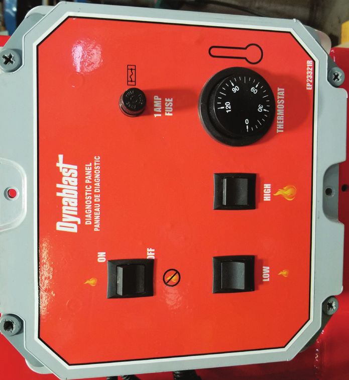
TABLE DE
                                    M AT I È R E S
INSTRUCTION DE SÉCURITÉ IMPORTANTES -------------------------------------------------------------3
INSTRUCTIONS DE PRÉ-UTILISATION ET D’INSTALLATION --------------------------------------- 4-5
PRÉCAUTIONS ET AVERTISSEMENTS -------------------------------------------------------------------- 6
INSTRUCTIONS DE BRANCHEMENT ET D’UTILISATION-------------------------------------------- 7-9
COMPOSANTES DE SÉCURITÉ --------------------------------------------------------------------------- 10
CARACTÉRISTIQUES -------------------------------------------------------------------------------------- 11
MANUEL DE PIÈCES ----------------------------------------------------------------------------------- 12-16
SCHÉMAS DE CÂBLAGE ------------------------------------------------------------------------------ 17-18
HIVERNAGE ------------------------------------------------------------------------------------------------- 19
SERVICE DE LA SPIRAL CHAUFFANTE ----------------------------------------------------------------- 20
GARANTIE -------------------------------------------------------------------------------------------------- 21

2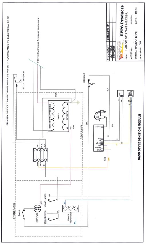
INSTRUCTIONS DE
          S È C U R I T É I M P O R TA N T E S
     AVERTISSEMENT - Lors de l’utilisation de ce produit, des précautions de bases doivent toujours être suivies.
                                                 Incluant ce qui suit.

1.    Lisez toutes les instructions de sécurité et d’utilisation avant l’opération de l’appareil.
2.    Pour réduire les risques de blessures, une surveillance particulière est nécessaire lorsqu’un produit est utilisé
      à proximité d’enfants.
3.    Lisez les avertissements sur les contenants d’additifs et consultez la fiche signalétique pour tout équipement
      de protection obligatoire qui doit être porté lorsque vous utilisez l’additif.
4.    Ventilez la zone de travail lors d’utilisation d’additifs toxiques ou irritant pour réduire votre exposition aux
      vapeurs toxiques.
5.    Portez des vêtements de protection, en particulier pour les yeux et la peau.
6.    Sachez comment arrêter le produit et perte de pression rapidement. Familiarisez-vous complètement avec
      les commandes.
7.    N’utilisez pas le produit lorsque vous êtes fatigué ou sous l’influence de l’alcool ou de drogues.
8.    Faites attention aux sols glissants. Certains additifs peuvent rendent une zone normalement sans danger
      extrêmement glissante et dangereuse.
9.    Gardez la zone d’opération dégagée de toute personne.
10.   Restez alerte - surveillez ce que vous faites.
11.   Ne dirigez pas la buse vers des endroits où des dommages ou des blessures pourraient arriver. La décharge
      d’eau de cette unité est soumise à une pression extrêmement élevée.
12.   Ne dirigez pas la buse vers une prise électrique, vous risqueriez un incendie, des chocs violents et des
      blessures corporelles.
13.   Ne faites jamais fonctionner l’appareil dans un endroit fermé. Les gaz d’échappement sont toxiques.
14.   Lorsque vous arrêtez de pulvériser, engagez toujours le loquet de sécurité du pistolet à gâchette.
15.   Lors du remplacement de buse, arrêtez toujours le moteur et libérez toujours la pression en actionnant
      le pistolet. Toujours engager le loquet de sécurité sur le pistolet à gâchette. Toujours changer la buse avec
      le pistolet et la baguette pointée loin de vous. Ne dirigez jamais la buse vers une personne ou un animal.
16.   Ne fumez pas lorsque vous manipulez du carburant ou gaz.
17.   N’abusez pas du boyau à haute pression en conduisant dessus. Le boyau peut se rompre et blesser un
      passant sans méfiance.
18.   Ne pas atteindre trop loin et se mettre debout sur un support instable. Gardez vos pieds à terre et équilibré
      en tout temps.
19.   Suivez les instructions de d’entretien spécifiées dans le manuel.
AVERTISSEMENT - UNE UTILISATION INCORRECTE PEUT CAUSER UN INCENDIE, UN CHOC GRAVE OU DES
                                  BLESSURES CORPORELLES.

                                     * CONSERVEZ CES INSTRUCTIONS *

                                                                                                                       3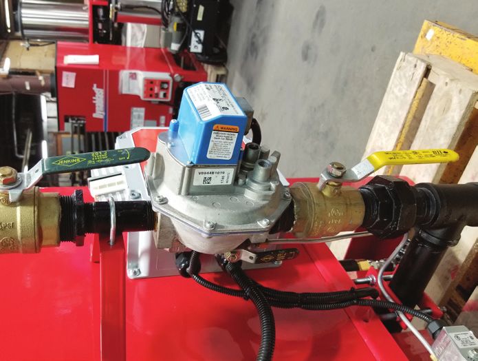
PRE-OPERATNG & INSTALLATION
              I N S T RU C T I O N S
When unpacking the unit, if you find damage due to shipping, contact your dealer or Dynablast Equipment
Immediately.

FUEL SUPPLY
For stationary installations, have the gas piping installed by a licensed gas fitter. This must be done in accordance
with the gas codes:
		               B149.1 for Natural Gas
		               B149.2 for Propane Gas

CAUTION: Propane gas is heavier than air and can collect in low hollow areas in an explosive mixture. Ensure that
the areas where you are operating the machines are ventilated, etc.

PROTECT FROM FREEZING – MOVING AND STORAGE
When Transporting or storing your module at temperatures below freezing, ensure the module has been properly
winterized (see winterizing your pressure washer).
Even an overnight frost can split a coil or crack a pump.
When lifting the heater use lifting hook welded to the top of heater coil. Before lifting the heater, make sure heater
coil is properly and securely bolted to heater frame assembly.

INDOOR INSTALLATION:
NOTE: Machines to be used indoors MUST be in accordance with local regulations and CSA Standards B139.
Make sure chimney is of suitable size. (10” minimum for MHGE700N/PSQ).
Make sure that there is enough air for combustion. (175sq.in. for MHGE700N/PSQ).
Be sure to protect against a down draft in below freezing weather. A DOWN DRAFT CAN CAUSE THE COIL TO
FREEZE, RESULTING IN EXPENSIVE DAMAGE!
Exhaust gases should not be vented in to a wall, a ceiling or a confined space of a building.

CHIMNEY SIZE
All venting shall be the same size or larger than the stack opening (10” for MHGE700N/PSQ series).
Never use vent pipe smaller than the stack opening.
If total run is more than 25’, use larger size chimney.
A 90 degree elbow is equivalent to a run of 20 feet.
If a horizontal run is used, make sure the flow rises at least 1/4” per foot.

4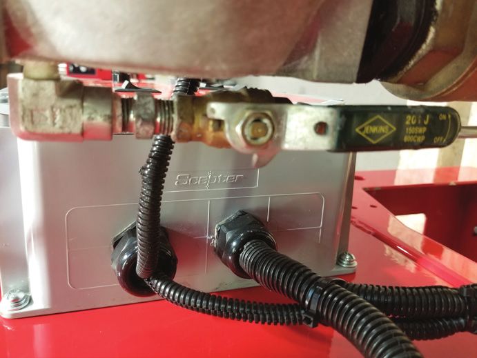
PRE-OPERATNG & INSTALLATION
               I N S T RU C T I O N S
COMBUSTION AIR SUPPLY
The MHGE700N/PSQ heater is comprised with an Atmospheric burner and requires air for combustion and
ventilation.
The appliance installer will know how and where to place a supply air duct. Take care that this opening will not
promote drafts which could blow out the pilot light.
Keep the area around the machine clear so this air can get to the burner.

APPLIANCE IN CONFINED SPACE
The confined space shall have two permanent openings: one near the top of the enclosure and one near the bottom
of the enclosure. Each opening shall have a free area of not less than one (1) square inch per 4000 BTU’s per hour
of the total input of all appliances within the enclosure. The openings shall have free access to the room interior which
should have adequate infiltration from the outside.

OUTDOOR ROOF STACK SPACING REQUIREMENTS
Must conform to local standards. Below drawing is a guide

        MINIMUM                                                                MINIMUM OF 2 FEET
        OF 2 FEET                                                                    ADJACENT
                                                                                     HIGH
                                                                                     BUILDINGS
INSTALLING SUPPLIED DRAFT HOOD

Place draft hood on top
of 10” stack.
Min. 1” overlap.
Fasten and secure with
4 sheet metal self-tapping
screws.

                                                                                                                        5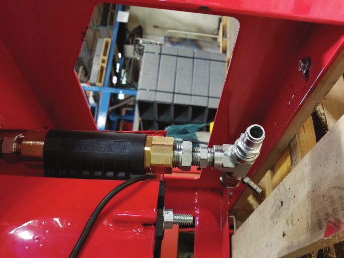
CAUTIONS &
                                WA R N I N G S
WARNING: IF YOU SMELL GAS, SHUT OFF THE GAS SUPPY TO THE APPLIANCE. EXTINGUISH ANY OPEN FLAME
AND TEST ALL JOINTS WITH A SOAP SOLUTION. IF THE ODOUR PERSISTS, CALL YOUR GAS SUPPLIER IMMEDIATELY
AVERTISSEMENT: SI UNE ODEUR DE GAZ EST DÉCELÉE, COUPER L’ALIMENTATION EN GAZ DE L’APPARIEL, ÉTEINDRE
TOUTES LES FLAMMES ET VÉRIFIER TOUS LES RACCORDS À L’AIDE D’UNE SOLUTION SAVONNEUSE. SI L’PDEUR
PERSISTE, AVERTIR IMMÉDIATEMENT LE FOURNISSEUR DE GAZ.

WARNING: RISK OF INJECTION OR SEVERE INJURY. KEEP CLEAR OF NOZZLE. DO NOT DIRECT DISCHARGE
STREAM AT PERSONS. THIS EQUIPMENT IS TO BE USED ONLY BY TRAINED OPERATORS.
AVERTISSEMENT: RISQUE D’INJECTION ET DE BLESSURES GRAVES. SE TENIR À L’ÉCART DU JET. NE PAS DIRIGER LE
JET DE SORTIE VERS D’AUTRES PERSONNES. CONFIER L’UTILISATION DE CE MATÉRIEL À UN OPÉRATEUR QUALIFIÉ.

CAUTION: THE MACHINE MUST BE ELECTRICALLY GROUNDED
ATTENTION: LA MACHINE DOIT ÈTRE MISE À LA TERRE

THIS MACHINE MUST BE ATTENDED DURING OPERATION
NE PAS FAIRE FONCTIONNER CETTE MACHINE SANS SURVEILLANCE

SUITABLE FOR CONNECTION TO TYPE A GAS VENT WHEN USED WITH THE PROVIDED DRAFT HOOD
S’ADAPTE À UN TUYAU D’ÉVACUATION DE GAZ DU TYPE B LORSQUE LA HOTTE DE TIRAGE FOURNIE EST UTILISÉE

A DRAFT HOOD SHALL BE INSTALLED
INSTALLER UNE HOTTE DE TIRAGE

6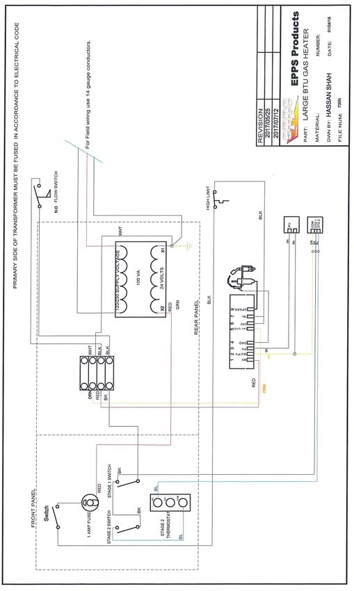
CONNECTING & OPERATING
                  I N S T RU C T I O N S
1. Make sure all switches are in the “OFF” Position.

2. Connect installed transformer to its rated power supply. The primary side of the control transformer must be fused
in accordance to the Canadian Electrical code. For power cord use rigid metal cable or armoured cable.

3. Join the inlet of the heater module to the high pressure outlet of the cold water pressure washer or pumping system.

4. Connect high pressure hot water hose to the outlet of the heater module.

                                                                                                     OUTLET
                                                                                                   1/2” QC (FP)
                                                                                                   (HOT WATER)

                                                                                                       INLET
                                                                                                   1/2” QC (MP)
                                                                                                  (COLD WATER)

NOTE: Prior to turning on Heater Module, spray a soap solution on all fittings and check for leaks. Ball valves must be
in an open position in order to check for leaks.

                                                                                                                     7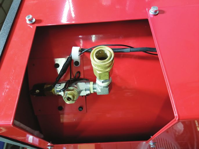
5. PILOT IGNITION SEQUENCE | GAS IS FIRST CONNECTED OR INTERRUPTED |
A. Open Ball Valve supplying Gas Valve and close the Ball Valve after the Gas Valve.
BALL VALVE
(OPEN)
GAS VALVE
BALL VALVE
(CLOSED)
B. Open ball valve supplying gas to the Pilot Valve.
BALL VALVE
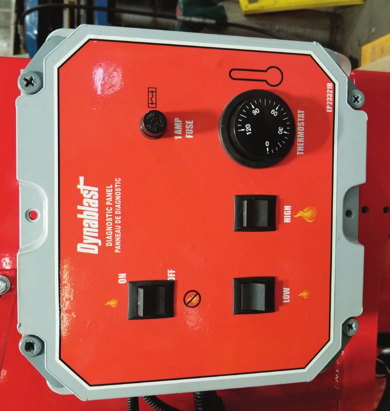
C. Turn on the Pilot valve switch to ignite the Pilot. The ignition sequence times out after 15 to 90 seconds
(depending on BTU rating). It is possible that the Pilot switch will have to be turned “ON” and “OFF” several
times before enough gas flows to ignite the pilot. Once Pilot is ignited leave the Pilot switch in the “ON”
position.
PILOT VALVE SWITCH
8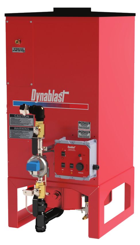
6. FIRING SEQUENCE | LOW & HIGH |
       A. Open ball Valve after Gas Valve.

                                                                                 BALL VALVE
                                                                                   (OPEN)
                    GAS VALVE

                                                                                 BALL VALVE
                                                                                   (OPEN)

     B. Turn on Switch labeled “LOW” to initiate the LOW FIRING RATE.

     C. When additional heat is required turn on Switch labeled “HIGH”.

     D. To initiate the “HIGH” firing rate turn the thermostat to the desired temperature.

     E. To cycle Heater “OFF”, turn thermostat to off position and then turn off “HIGH” firing switch. Then Turn off
        “LOW” firing switch to completely cycle off. After above stage Pilot will only be on. To turn off Pilot, switch
        off Pilot Valve Switch. When Heater Module is not in operation, close all ball valves.

                                                                                             “HIGH” FIRE

          GAS VALVE

                                                                                           THERMOSTAT
                                                                                        (ENGAGES HIGH FIRE)

                                                                                                                          9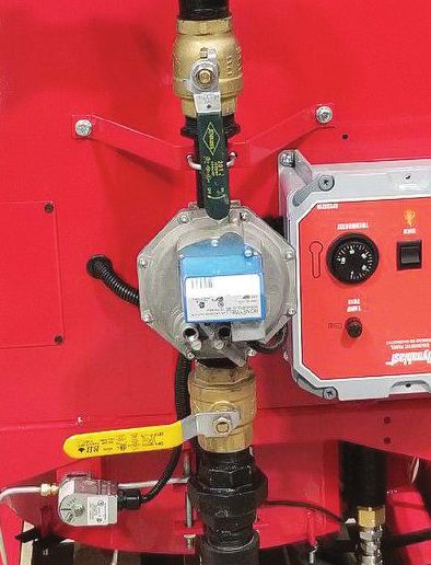
SAFETY
                              COMPONENTS
FLOW SWITCH
The flow switch prevents the burner from being turned on if there is insufficient water. Proper water flow causes
the magnetic core to be pushed up, closing the reed contact. This contact is interlocked with the fuel control.

SAFETY RELIEF VALVES
The Relief Valve prevents the machine from being subjected to abnormally high pressures. If this situation occurs,
the valve will blow off relieving the pressure in the coil. This valve may also operate if the unloader is adjusted
too high.
                                       HOT WATER SETTING (3800-4200psi)
                                           STEAM SETTING (550-700psi)

THERMOSTAT
The built-in thermostat stops the unit from overheating. Maximum temperature of the unit is 305°F (150°C) for
steam and 220°F (105°C) for hot water. Above this temperature, the burner stops automatically.

THERMOSTAT (MC7211)
This is an adjustable dial thermostat which Is limited by the high limit switches. This thermostat is used on the 3007
DI and 3009 DI.

HIGH LIMIT SWITCH (STEAM)
The High Limit Switch is a thermostat which operates at a higher temperature than the built-in thermostat, about
320°F (160°C). This switch is not adjustable and will only operate when other controls fail to keep the water
temperature within the normal operating range. This switch cuts the power to the burner.

HIGH LIMIT SWITCH (HOT WATER)
The High Limit Switch is a thermostat which operates at a higher temperature than the built-in thermostat, about
230°F (110°C). This switch is not adjustable and will only operate when other controls fail to keep the water
temperature within the normal operating range. This switch cuts the power to the burner.

FUSES
1 AMP fuse protecting the 24VAC Secondary side of Transformer (safety controls side).

                  WARNING – DO NOT TAMPER WITH THESE DEVICES

10
SPECIFICATIONS, FEATURES
& OPTIONS
MHGE700N/ MHGE700N/
MODEL
PSQ PSQ-160
PRESSURE PSI 3500 5000
BTU’S:
HIGH ALTITUDE - 479,000 - 525,000 479,000 - 525,000
HEATER SEA LEVEL
MODULE PROPANE/ PROPANE/
GAS
NATURAL GAS NATURAL GAS
POWER SUPPLY 120V/230V 120V/230V
VOLTAGE 50/60Hz 50/60Hz
INPUT
15 INCHES 15 INCHES
PRESSURE
MANIFOLD
SPECIFICATIONS PRESSURE 1.00-3.75/ 1.00-3.75/
(WC-INCHES)
ORIFICE SIZE #55/69 #55/69
THERMOSTAT YES YES
FLOW SWITCH YES YES
HIGH TEMP
YES YES
LIMIT PROTECTOR
HIGH PRESSURE
YES YES
SAFETY RELIEF VALVE
COMPONENTS FINISH Polyester Powder
DIMENSIONS
24x24x58
(LxWxH)
DRAFT HOOD SIZE
10” 10”
(DIAMETER)
WEIGHT (POUNDS) 900 1020
COIL - PIPE
PIPE SCHEDULE
SCH 80 ¾” SCH 160 ¾”
11PARTS B R E A K D O W N
COIL ASSEMBLY BREAKDOWN (3007 GAS FIRED)
COIL ASSEMBLY BREAKDOWN
Number Part Number Description Quantity
1 700N Coil 1
2 FIMP113-D4 1/2H 1/2" SCH 80 NIPPLE 1
3 FIS1002-D 1/2" NPT Cross 1
4 EP40096 Thermostat Well Bushing 1
5 ELTR86 Thermostat 1
6 ELT44110 High Limit 1
7 FIS1015-D 1/2" NPT Street Elbow 2
8 FIS1022-D 1/2" NPT NIPPLE 1
9 EP22208 FP 1/2" FP Female Quick Coupler 1
10 FIMP113-D4H 1/2" MP SCH 80 Nipple 4" 1
11 FIS3526-8D 1/2" FP Female JIC 1
12 FI48-6D 3/8" MP Male JIC 1
13 PUST5/PUST6/PUTMT/ Flow Switch 1
14 FIS1022-DC 1/2" X 3/8" Hex Bushing 1
15 FIS1001-D 1/2" NPT Tee 1
16 PUGP100884 Relief Valve 1
17 EP22217 MP 1/2" MP Male Quick Coupler 1
12PARTS B R E A K D O W N
(GAS ASSEMBLY)
13PARTS B R E A K D O W N
(GAS ASSEMBLY)
GAS ASSEMBLY
Number Part Number Description Quantity
1 HEX88 X88 Burner Ring 1
2 N/A Burner Spud 88
3 N/A 1 1/2" MP Square Plug 1
4 HEQ3451 Standing Pilot 1
5 EP24617 Stainless Steel Shield 1
6 EP24831 Standing Pilot Bracket 1
7 N/A 1/8" MP x 1/4" Tube Compression Fitting 1
8 N/A 1/4" Tube 2
9 N/A 1/4" MP x 1/4" Tube Compression Fitting 3
10 HEV8046C Solenoid Valve 1
11 EL3200 1/2" MP Strain Relief 1
12 FIBV2103-B-CGA 1/4" FP Brass Ball Valve 1
13 FIS1022-B 1/4" FP Hex Nipple 1
14 FIS1015-BA 1/8" MP x 1/4" FP Elbow 1
15 FI103-A 1/8" FP Hex Coupler 1
16 FI112-A 1/8" MP Hex Nipple 1
17 FIMP113-H3 1 1/2" MP x 3" Pipe 3
18 FIMP100-H 1 1/2" FP Elbow 2
19 FIMP113-H9 1 1/2" MP x 9" Pipe 1
20 FIMP101-H 1 1/2" FP Tee 1
21 FIMP110-HB 1 1/2" x 1/4" Hex Bushing 1
22 FI118-B 1/4" MP Brass Plug 1
23 FIMP113-H2 1 1/2" MP x 2" Pipe 2
24 FIMP104-H 1 1/2" Union Joint 2
25 FIBV2103-K-CGA 1 1/2" FP Brass Ball Valve 2
26 FIMP110-HF 1 1/2" x 1" Hex Bushing 2
27 FIMP113-F1 1/2 1" MP x 1 1/2" Pipe 1
HEV8944B1019/
28 Gas Control Valve (Natural Gas/Propane) 1
HEV8944C1017
29 FIMP113-F5 1" MP x 5" Pipe 1
N/A – NOT AVAILABLE
14PARTS B R E A K D O W N
(ELECTRICAL BOX ASSEMBLY)
15PARTS B R E A K D O W N
(ELECTRICAL BOX ASSEMBLY)
ELECTRICAL BOX ASSEMBLY
Number Part Number Description Quantity
1 ELJBX884 8" X 8" Electrical Box 1
2 EL3234 3/4" NPT 3/4" Strain Relief 2
3 EL3200 1/2" NPT 1/2" Strain Relief 1
4 EL1706 3/4" NPT Conduit Locknut 2
5 EL1704 1/2" NPT Conduit Locknut 1
6 NOT AVAILABLE 9 1/4" X 8" Electrical Panel 1
7 ELMH100MG Transformer 1
Electronic Ignition SPECIFY BASO (50Hz) OR
8 HES8610U1003 1
HONEYWELL (60Hz) WHEN ORDERING
9 ELUNPA44-12 Terminal Strip 4
10 ELTR86 Thermostat 1
11 EL345603 Fuse Holder 1
12 ELGGC1 1 Amp Glass Fuse 1
13 EL2504-11E Selector Switch 3
HEV8944B1019/
28 Gas Control Valve (Natural Gas/Propane) 1
HEV8944C1017
29 FIMP113-F5 1" MP x 5" Pipe 1
16WIRING D I A G R A M S
GAS VALVE WIRING(700N)
700N (HONEYWELL ELECTRONIC IGNITION)
REVISION
2017/08/25
2017/07/12
DYNABLAST EQUIPMENT
PART: Large BTU Gas Heater
MATERIAL: NUMBER:
DWN BY: HASSAN SHAH DATE: 01/04/18
FINE NUM: 700N
1718
REVISION
2017/08/25
2017/07/12
DYNABLAST EQUIPMENT
PART: Large BTU Gas Heater
MATERIAL: NUMBER:
700N (BASO ELECTRONIC IGNITION)
DWN BY: HASSAN SHAH DATE: 01/04/18
FINE NUM: 700N
WIRING D I A G R A M SWINTERIZING
YO U R H E AT E R M O D U L E
(This is also good practice if the heater module is to remain unused for more than 3 - 4 weeks or transporting/
storing in freezing temperatures.)
WITH A FLOAT BOX
• Shut off the water supply, and disconnect hose.
• Remove cover from Float Box.
• Run the pressure cleaner until the level of the water in the Float Box is just above the outlet screen.
• Turn off the cleaner.
• Fill the Float Box to about 3/4 with windshield washer or antifreeze.
• Turn on the cleaner and open gun until liquid comes out of nozzle “foamy” or “soapy”.
CAUTION: If your hose is longer than 35 feet, the float box may empty before the liquid from the
nozzle gets foamy. If this happens, refill the float box with antifreeze and continue.
• Put gun in OFF position for five seconds to allow antifreeze into bypass line.
• Shut off motor - unit is now winterized.
WITHOUT A FLOAT BOX
• Shut off the water supply and disconnect hose.
• You need a short (’) length of hose with a male garden hose fitting on one end.
• Connect the short hose to the inlet of the machine.
• Put the other end of the hose into a container of windshield washer or antifreeze.
• Turn on cleaner and open gun until liquid comes out of nozzle “foamy’ or “soapy”.
• Put gun in OFF position for 5 seconds to get antifreeze into bypass line. Shut off motor
Unit is now winterized.
THINGS TO CHECK REGULARLY
1. Check for System leaks. Leaks in the pressure side of the system can cause premature wear (even failure)
of the pump. The warning signals for these kinds of leaks are frequent cycling of the unloader at least more
than once in 2 minutes.
2. After you use chemical additives thoroughly FLUSH the system with clean water.
3. Inspect the POWER CORD regularly. Also check for POWER OUTLET SOCKET. For safety, replace worn or
damaged parts immediately.
4. Never run the heater module without water. TURN WATER ON FIRST.
5. PROTECT FROM FREEZING! When transporting your heater module in temperatures below 2°F/0°C
WINTERIZE the heater coil, pump, hose and gun.
6. Check gas fittings for leaks.
7. Inspect all hoses for leaks and cracks, replace when hoses are damaged or worn.
19COIL S E R V I C E
CLEAN HEATING COIL
Remove burner from coil by removing the four flange mount nuts. Inspect inside of combustion chamber and if it is
heavily sooted so that air passage could be a serious problem, clean the air passage with a heavy duty vacuum.
Run machine at full pressure and check the inside coil for leaks.
COIL MAINTENANCE
Liming of the coils is caused by mineral deposits from the water and occurs in hard water areas. The deliming
procedure requires special caution and tools to perform. We recommend that you call your local service person if
problems arise.
CHECKING FOR SCALE OR LIMING IN THE COIL
1. Remove outlet orifice and check for any liming. Clean the orifice if needed.
2. Remove outlet gun and hose.
3. Install a pressure gauge between the unloader and coil inlet.
4. Turn on the pump without the water outlet gun or outlet orifice. If the pressure reading is above 50 psi, have
your machine descaled. Else, reassemble the machine.
DESCALING
If pressure drop in the coil is over 50 psi - descaling is recommended. Descaling requires that use of highly
corrosive chemicals. It also requires the use of goggles and special protective clothing.
1. This procedure requires a 20L pail of descaling chemical.
2. Plumb the pump suction into the pail of descaling compound with a screen on the end of the suction line.
3. Plumb a hose from the machine outlet back in the pail of descaling compound.
4. Turn the pump on and circulate the compound through the machine for about 20 minutes.
5. After that time the chemical being pumped out of the coil should be running thin and dirty rather than
foaming heavily.
6. Remove the extra plumbing and reconnect machine together and run clean cold water through the machine
for five minutes.
20DYNABLAST WA R R A N T Y
HOT WATER HEATER MODULE
This product is warranted to be free from defects in materials and workmanship under normal use and service,
for a period of (1) one year from the date of purchase, unless stated otherwise below, when operated and
maintained in accordance with the Maintenance and Operation Instructions supplied with the unit. The warranty
does not cover misuse or negligence.
This warranty is extended only to the original purchaser. Hoses, spray guns, wands, nozzles and other
accessories are warranted for 90 days. Warranty is void if repairs are attempted by anyone other than an
Authorized Service Centre.
If a difficulty develops with the product, you should contact the nearest Authorized Repair Centre or Dynablast
office. Only these locations are authorized to make repairs to the product or replacement of defective parts,
which will be done at no charge within a reasonable time after receipt of the product. Units or parts should be
returned at the customer’s expense to the nearest Dynablast location or Authorized Service Centre. Pack unit in
a strong carton and pad tightly to avoid damage. Damage in transit is not covered by warranty. Include original
purchase receipt with any claim (but keep a copy for your files).
Dynablast’s liability for special, incidental or consequential damage is expressly disclaimed. In no event shall
Dynablast’s liability exceed the purchase price of the product in question. Warranty is limited to repair of the
product and/or replacement and is the discretion of Dynablast. There are no expressed warranties other than
those specified herein.
SPECIAL WARRANTIES WARRANTY PERIOD
Fabricated Components
1 Year Parts | 1 Year Labour
(Frame, Coil Skin, Coil Cap)
Burner, Transformer, Control Switch,
1 Year Parts | 1 Year Labour
Safety Switch Pressure
Schedule 80, 160 Heating Coil Limited Warranty
3 Year Parts | 1 Year Labour
*(See Below)*
*We must receive the coil serial number section of the coil to substantiate the warranty claim*
We will not replace coil under warranty if the coild have been subjected to misuse such as:
1. Freezing | 2. Lime Deposit | 3. Other Foreign Material Deposit | 4. Shock or Vibration
21Vous pouvez aussi lire