NOTICE D'UTILISATION CLIC-IT MOUNTAIN 26.07.2014
←
→
Transcription du contenu de la page
Si votre navigateur ne rend pas la page correctement, lisez s'il vous plaît le contenu de la page ci-dessous
DC002-14 E.O.

                                                                NOTICE D’UTILISATION
                                                                CLiC-iT MOUNTAIN
                                                                26.07.2014

                SARL DEHONDT 7 rue pierre Pflimlin – 51100 – Reims – France – Tel.: + 33 (0)3 26 47 11 34 - Site: www.clic-it.eu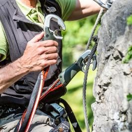
1 Sommaire

             Introduction
             Cette notice d’utilisation contient des informations importantes, une carte de
             contrôle et une preuve d’inspection.

             La notice doit être conservée avec le produit pendant sa durée de vie.

             Les illustrations de cette notice sont non contractuelles.

             Page 2          Descriptif du produit

             Page 4          Préconisations utilisateur

             Page 9          Manœuvres interdites

             Page 11         Informations exploitant

                              AVERTISSEMENT
                              Les activités impliquant l’utilisation de ce produit sont par nature

                  !           dangereuses.
                              Avant utilisation de ce produit la notice doit avoir été lue et son
                              contenu compris.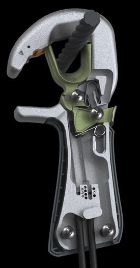
2 Descriptif du produit CLiC-iT                            MOUNTAIN

 Spécificités : Ce produit est un équipement de protection individuelle pour l’auto-
 assurage sur câble en « via ferrata » (norme EN 958).

 Ce produit est constitué d’une longe munie d’un absorbeur d’énergie et de 2 connecteurs
 qui intègrent 3 niveaux de sécurité :
     1    Détection d’ancrage métallique (disponible selon les versions)
     2    Gâchette de déverrouillage sécurisée
     3    Synchronisation d’ouverture/fermeture

 Longe
 La longe comporte une boucle 4 en partie centrale, munie d’un absorbeur
 d’énergie 5 et destinée à être reliée à un harnais conforme à la norme EN12277.
 La longe comporte en option un 3e point de repos 6.
 Il existe 4 versions de boucle:

M3 La longe comporte une boucle     4   en partie centrale, munie d’un absorbeur d’énergie 5.
M4 Longe M3 + un 3e point de repos       6.
M8 La longe comporte un émerillon CLiC-iT (7) cousu dans la boucle d’un absorbeur d’énergie     5.
M9 Longe M8 + un     3e   point de repos 6.

                                                               ø 8 mm min
                                                                     ø 21 mm max
 Connecteurs
 Les Connecteurs permettent de s’arrimer
 sur des ancrages ou sur une ligne de vie.
                                                                                                     M8   M3
                                                                           1
 Le diamètre des ancrages doit être compris                     2                                    M9   M4
 entre 8 et 21 mm.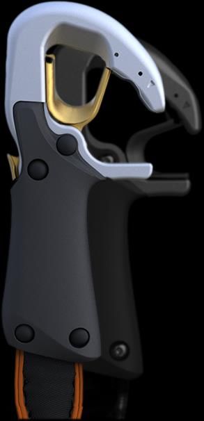
3 Descriptif du produit CLiC-iT   MOUNTAIN

                                                                                          Goupille de
                                                   Bascule
                                                                                          glissement
                                                   de détection
                                                   + Aimant

                                                    Barillet

                                                                                                Gâchette
                                                    Loquet

   Connecteur en position fermée (sur ancrage) F    O Connecteur en position ouverte (libre)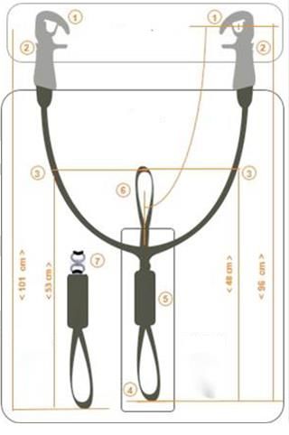
4 Préconisations utilisateur

          Fixer un Connecteur :
          Cliquez !

          Chaque connecteur (sauf sur
          version DAS020 Mx0) intègre un      O
          dispositif de détection d’ancrage
          qui empêche de les fixer sur un
          ancrage qui ne soit pas en acier
          (magnétisable).

                                                  1 Tenez le connecteur                2 Positionnez le nez du
                                                  ouvert par la poignée.               connecteur devant un
         3 Placez la flèche du                                                         ancrage magnétisable.
         connecteur en face de l’ancrage
         pour libérer le barillet…

                                                                                   F

          3bis Attendez que le                    4   Poussez le connecteur            5    Ce connecteur étant
          barillet soit libéré : le système       en position fermé sans forcer.       cliqué, l’autre pourra être
          de détection d’ancrage "s'auto-                                              décliqué.
          verrouille" si l'on force.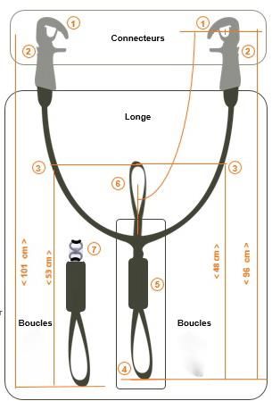
5 Préconisations utilisateur

        Retirer un Connecteur :
        Décliquez !

        CLIC-IT intègre un mécanisme
        empêchant le décrochage d’un
                                                       F
        connecteur si l’autre est déjà déverrouillé.

        Il n’est pas possible d’enlever
        simultanément les 2 connecteurs (dans
        les conditions normales d’utilisation).

                                                       1 Tenez le connecteur par       2   Actionnez la gâchette
                                                       la poignée.                     avec le pouce.

                                                                                   O

          3    Retirez le connecteur en maintenant la gâchette appuyée.                4    Le connecteur est ouvert,
                                                                                       il peut-être fixé à un nouveau
                                                                                       point d’ancrage.
6 Préconisations utilisateur

    Monter sur un
    parcours

    Lors de la montée sur le
    parcours, il faut vérifier qu’un
    connecteur est ouvert.

    Si le 2 connecteurs sont
    fermés, engagez les tous les
    2 par une extrémité libre de
    câble en dehors d’une zone
    de danger de chute, puis
    suivre les instructions pour
    ouvrir 1 connecteur.               1 Repérez le connecteur       2 Engagez le dans               3 Cliquez le deuxième
                                       fermé   F                     l’extrémité libre de câble.     connecteur sur le câble.

    4 Décliquez le premier connecteur en appuyant sur sa gâchette.   5 Cliquez le sur le câble       6 Les 2 connecteurs sont
                                                                     auprès de l’autre connecteur.   verrouillés sur le câble, vous
                                                                                                     pouvez commencer le parcours.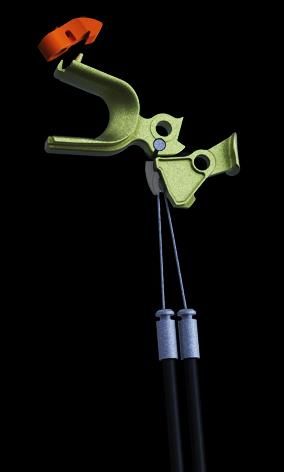
7 Préconisations utilisateur

    Sortir d’un parcours

    Procédure à réaliser
    uniquement à la sortie d’un
    parcours, en dehors de la
    zone de danger de chute.

    Respecter les consignes de
    l’encadrement / sortie de
    parcours

                                  1 Les 2 connecteurs sont      2 Décliquez un connecteur      3 Présentez ce connecteur
                                  verrouillés sur le câble.     en appuyant sur sa gâchette.   sur l’entrée libre du parcours.

    3bis Cliquez -le sur          4 Sortez-le ensuite sans le   5 Décliquez l’autre            6 Les 2 connecteurs sont
    l’extrémité libre.            décliquer.                    connecteur en appuyant sur     complètement dégagés.
                                                                sa gâchette.
8 Préconisations utilisateur
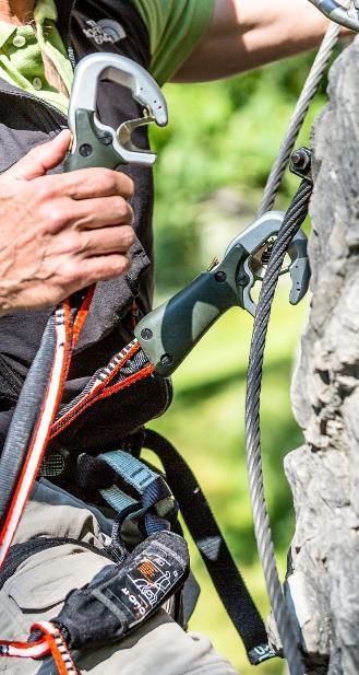
Progression sur câble
Pour votre sécurité, connectez obligatoirement les deux connecteurs de la longe double sur le câble
de « via ferrata ».
En doublant les systèmes, vous réduisez les risques de défaillance.
Lors des passages d’ancrages, votre sécurité n’est plus assurée que par un connecteur (il n’y a plus
de redondance).
Soyez particulièrement vigilant lors des transferts de connecteurs.
ATTENTION, tout appui de l’extérieur sur le barillet ou sur le corps du connecteur est dangereux. Il
pourrait endommager le produit et entraîner son décrochage.
ATTENTION le brin de repos doit rester libre. Ne le fixez pas au baudrier, sinon l’absorbeur d’énergie ne fonctionne pas correctement.
Lors de la progression, s’assurer qu’aucun objet ne soit placé autour de l’absorbeur d’énergie. Ceci risquerait d’empêcher son bon fonctionnement.
OK OK X X9 Manœuvres interdites
Négliger les règles basiques
X X X
d’utilisation peut entraîner un défaut
du produit pouvant occasionner des
blessures pour l’utilisateur.
Les quelques cas de mauvaise
utilisation présentés dans cette notice
ne sont pas exhaustifs. Il existe une
multitude d’autres mauvaises
utilisations impossible à énumérer ici.
Ne pas essayer de forcer Ne pas vriller les longes Ne pas tordre les longes
l’ouverture des connecteurs ni volontairement. volontairement.
de manipuler le barillet à la
main. Ne pas mettre la main
entre le câble et le connecteur.
X X X
Ne pas accrocher le fourreau Ne pas laisser tomber ni Ne pas tirer sur les
de la longe, ceci pourrait traîner les connecteurs au connecteurs ou sur la
endommager la longe. sol. longe pendant la tyrolienne.10 Manœuvres interdites
X X X X
Ne pas essayer de fixer les Ne pas verrouiller le Ne pas frapper les
Ne pas placer la tête entre les 2
connecteurs sur la longe, connecteur sur un outil, connecteurs entre eux.
longes, car risque
ni sur le harnais, ni sur un objet en acier
d'étranglement en cas de chute.
une branche, une corde (magnétisable) autre qu’un
(autre qu’un ancrage). ancrage, ou sur un aimant.
X
Vérifier en début de
parcours que le
connecteur est bien
verrouillé sur le câble.INFORMATIONS EXPLOITANT
CLiC-iT MOUNTAIN
SARL DEHONDT 7 rue pierre Pflimlin – 51100 – Reims – France – Tel.: + 33 (0)3 26 47 11 34 - Site: www.clic-it.eu11 Informations exploitant : Briefing
Faire manipuler CliC-iT par les Ne pas vriller les longes. Poser les connecteurs devant Transporter le matériel sur le
pratiquants au sol (sur un câble la poulie pour la tyrolienne, afin baudrier au moyen du support
tendu) avant de monter sur le -Si la longe est vrillée et 1 de limiter le frottement sur le connecteurs (accessoire en
parcours. connecteur bloqué verrouillé: câble. option).
Oter l'autre connecteur et dé-
vriller la longe. Evacuation
- Si 2 connecteurs sont
verrouillés (plusieurs vrilles):
Ecarter les connecteurs en
tendant la longe, et ôter l'un
ou l'autre des connecteurs.
Fournir 1 mousqueton en Utiliser l'outil recommandé pour
acier zingué aux opérateurs déverrouiller les 2 connecteurs si le
pour décrocher un pratiquant mécanisme est bloqué. Toujours
en cas d'urgence. emmener cet outil avec soi afin d’éviter de
rester éventuellement bloqué sur le câble.12 Informations exploitant : Aménagements nécessaires
Installer des ancrages avec Sur les tyroliennes, la longe de Stocker le matériel avec les
une extrémité libre en début et la poulie doit être significa- mousquetons vers le bas afin
fin des parcours, uniquement tivement plus courte que la d’évacuer l’humidité dans les
dans une zone hors de danger longe CLiC-iT afin que les câbles de la longe.
de chute. connecteurs ne frottent pas sur
le câble de tyrolienne.
Extrémités à protéger par un
capuchon plastique pour éviter
de blesser l’utilisateur.
S’assurer que tous les
ancrages soient en acier
magnétisable (sauf pour la
version DAS020 Mx0).13 Informations exploitant Mode d’emploi : Respecter impérativement les schémas d’utilisation du produit. Fixation de l’Equipement de Protection Individuelle à la personne : Attacher la boucle au pontet ou à l’anneau ventral du harnais en utilisant un nœud en tête d’alouette. 1 Passez la boucle de la 2 Passez le premier 3 Passez le deuxième 4 Tirez la longe pour former longe dans le pontet (ou dans connecteur dans la boucle connecteur dans la boucle le nœud en tête d’alouette. l’anneau sternal) du harnais. de la longe. de la longe. Le mousqueton à fixer sur le brin de repos doit être de type K conforme à la norme EN 12 275. Insérez un STRING sur la sangle et fixez le mousqueton. Le STRING permet de garder le mousqueton suivant le grand axe et de protéger la sangle de l’usure.
14 Informations exploitant

Précautions d’emploi                                                                    ATTENTION (2) : Sur les « via ferrata » qui n’ont pas de
Les différents composants de la                                                         boucles de câble, le connecteur heurte directement l’ancrage.
chaîne d’assurage doivent être                                                          Cette sollicitation du connecteur peut occasionner une rupture
conformes aux normes                                                                    du produit.

                                         1m
européennes de sécurité (CE), et
être utilisés en toute connaissance                                                     Dans les 2 cas ci-dessous, assurez vous avec une corde en
de leurs limites d’utilisation.                                                         respectant les techniques d’escalade.

                                              Chute libre maxi = 5 m
La distance entre deux points d’arrêt                                              OK                                   X
doit être au maximum de 3 m afin
de limiter la chute à 5 m (croquis ci-

                                         3m
contre).

ATTENTION (1) : Lorsque deux
points d’ancrage
sont espacés de plus de 3 m, la
hauteur potentielle de chute peut
                                         1m

être supérieure à 5 m. La force de
choc peut être trop importante et
                                                                   Amortissement

occasionner une rupture de                                                         OK
                                         1m

                                                                     du choc

l’absorbeur.

                                                                                                           +                    =
15 Informations exploitant
Contrôle du produit (longes M3/M4)
Avant chaque utilisation :
• Inspecter les coutures de la longe
• Inspecter visuellement l’état de la longe et des
coutures, ouvrez le fourreau de protection de
l’absorbeur d’énergie et vérifiez que les sangles
à déchirement ne sont pas déchirées.
• Vérifiez le bon fonctionnement des
connecteurs, notamment que :
- Les 2 connecteurs ne peuvent se
déverrouiller simultanément.
- Les connecteurs ne peuvent s’ancrer
que sur un ancrage en acier
(magnétisable), sauf sur version DAS020
Mx0.
- Il n’est pas possible de déverrouiller un
connecteur sans appuyer sur la gâchette.
- Les connecteurs se verrouillent
automatiquement
Contrôle du produit (opérations supplémentaires longes M8/M9)
• Vérifiez également l’absence de fissure, de
Avant chaque utilisation :
déformation et de corrosion.
• Inspecter l’emerillon CLiC-iT 24kN conformément à sa notice d’utilisation,
Si un défaut de fonctionnement survenait, le
• Inspecter visuellement l’état des coutures liant l’emerillon à la longe et la liaison absorbeur
produit devrait alors être immédiatement contrôlé.
d’énergie.
Si un défaut de l’emerillon (fonctionnement + usure) survenait, le produit devrait alors être
Contacter systématiquement le fabricant pour tout
immédiatement retiré et contrôlé par le fabriquant.
cas de fonctionnement incorrect.
Contacter systématiquement le fabricant pour tout cas de fonctionnement incorrect.16 Informations exploitant
Avertissement Chutes : Attention
Avant chaque utilisation, vérifiez visuellement la bonne installation de la Ce produit ne doit pas être utilisé après une chute ayant provoqué un
longe sur le harnais. Réalisez un test de suspension en étant contre- déchirement de l’absorbeur d’énergie. Il doit être immédiatement rebuté.
assuré ou en terrain sécurisé. Si vous utilisez des longes M8-M9 réaliser Des mises en tensions brutales répétitives ou des petites chutes,
un contrôle visuel de l’emerillon et vérifier la bonne rotation de celui-ci peuvent amorcer le déchirement. Renvoyer immédiatement le produit
durant le test de suspension, pour remplacement de l’absorbeur si le déchirement est amorcé.
Lors de la mise en place du produit sur le site, il faut veiller dans les Poids de l’utilisateur (y compris le poids de l’équipement) : entre 50 et
zones de risque de chute, à ce que l’utilisateur ne puisse pas fixer les 100 kg .Pour les utilisateurs dont le poids est en dehors de cette plage
connecteurs à un outil, un aimant, un élément métallique magnétisable, progresser contre-assuré par une corde pour éviter une chute
une extrémité libre de câble, autre que la ligne de vie. importante, avec l’aide d’un professionnel de l’assurage sur corde.
Veiller également à ce que l’utilisateur connecte bien ses deux Précautions particulières
connecteurs à la ligne de vie au début du parcours. Eviter tout frottement sur des zones abrasives ou tranchantes qui
pourraient endommager le produit. Afin de ne pas dégrader les
Ce produit est destiné exclusivement aux activités de « via ferrata ». performances du matériel, les températures d’utilisation et de stockage
doivent être comprises entre - 10 et +50 °C.
La pratique de la « via ferrata » est par nature dangereuse. Vous êtes Eviter le contact avec des produits chimiques, notamment les acides qui
responsable de vos actes et de vos décisions. Avant d’utiliser cet peuvent détruire les fibres des longes sans que cela ne soit visible.
équipement vous devez :
• Lire et comprendre toutes les instructions d’utilisation Effets de l’humidité et du gel
• Vous former spécifiquement à l’utilisation de cet équipement Tout équipement humide doit être séché dans un endroit sec et aéré à
• Vous familiariser avec votre équipement, apprendre à connaître ses distance de toute source de chaleur directe. Un équipement humide ou
performances et ses limites qui a subi l’action du gel a des caractéristiques techniques réduites.
• Comprendre et accepter les risques induits
Tout manquement à ces règles peut être la cause blessures graves ou
mortelles.
Stockage et transport
Stocker et transporter dans un endroit frais et sec, à l’ombre.
L’apprentissage des techniques et une compétence particulière sont Eviter l’exposition inutile aux UV. Stocker et transporter sans contraindre
requises pour l’utilisation de ce produit. mécaniquement le produit.
Ce produit ne doit être utilisé que par des personnes compétentes
avisées ou bien l’utilisateur doit être placé sous le contrôle visuel direct Nettoyage des longes
d’une personne compétente. Frotter avec une brosse souple non agressive. Ne pas utiliser d'eau.
Le propriétaire de ce produit est responsable de ses propres actions et
décisions. Il doit également tenir à disposition cette notice d’utilisation à
un tiers qui utilise ce produit.17 Informations exploitant
Nettoyage des Durée de vie
connecteurs La durée de vie correspond à la durée de stockage + durée d’utilisation.
Afin d’enlever les poussières à
l’intérieur des connecteurs (autour Durée de stockage : dans de bonnes conditions de stockage, ce produit
de l’aimant et à l’intérieur du peut être entreposé pendant 5 ans avant première utilisation sans
mécanisme), utiliser un pistolet à affecter sa future durée d’utilisation.
air comprimé (pression maximum :
6 bars). Durée d’utilisation : 10 ans pour une utilisation occasionnelle, 3 ans
pour une utilisation régulière, 1 an pour une utilisation intensive.
Afin d’assurer un fonctionnement
suave sans grippage et de Ces durées sont indicatives. C’est le contrôle du produit qui détermine
protéger le système de l’humidité, si un produit doit être mis au rebut.
pulvériser du lubrifiant WD40
toutes les 2 semaines à l’intérieur Un produit doit être mis au rebut ou retourné au fabricant pour
du mécanisme. réparation si :
• Usure importante des connecteurs dans la zone de contact du câble
Révision d’arrimage.
• Défaut d’ouverture ou de fermeture des connecteurs, possibilité
Ce produit doit être retourné au fabricant pour être contrôlé de manière
d’ouvrir simultanément les 2 connecteurs, ou possibilité de fixer un
approfondie tous les ans. Il est interdit de modifier ou réparer vous-
connecteur sur un ancrage d’un matériau autre que acier
même ce produit, sans une formation et une certification écrite
magnétisable : corde, harnais, longe.
préalable de la SARL DEHONDT.
• Les sangles sont endommagées par abrasion, coupure, agents
chimiques ou autres.
• L’absorbeur d’énergie est décousu ou déchiré (ouvrir le fourreau de
Informations importantes protection).
• Les coutures des sangles sont endommagées.
Performances lors d’examens techniques : • Le produit a été au contact avec des agents chimiques ou
Résistance statique du produit : selon le grand axe doigt fermé : 25 kN, dangereux.
selon le petit axe : 7 KN
En cas de chute ou de dommage important, le produit doit être retiré
Accessoires utilisables avec l’EPI : immédiatement et retourné au fabricant pour une inspection détaillée et
Crochet de rangement connecteurs fixé au harnais. une réparation éventuelle. Un rapport de l’incident doit être joint au
fabricant avec le produit.
Classe de protection :
3. Risque de chute mortelle.18 Informations exploitant
Signification du marquage / Référence des directives appliquées / Nom et adresse de l’organisme notifié intervenant dans la phase de conception
des EPI :
Longe avec absorbeur d’énergie
CLIC-IT Marque commerciale
MOUNTAIN Modèle
Conformité à la directive Européenne EPI 89/686/CEE
0082 Numéro de l’organisme de certification :
APAVE SUDEUROPE SAS
BP 193 13322 Marseille Cedex 16 FRANCE
Organisme notifié intervenant pour l’examen CE de type : APAVE
SUDEUROPE SAS
EN 958 Norme EN 958 + A1 de 2010 + fiche CNB/P/11.099 de fév.2013
Absorbeur d’énergie utilisé en « via ferrata »
Lire attentivement la notice avant utilisation du produit
SARL DEHONDT Fabricant
Nom de la société : DEHONDT SARL
Adresse : 17 allée Blaise Pascal 51 430 Tinqueux
Téléphone : 06 51 56 78 77 Email : contact@clic-it.eu19 Informations exploitant
Etiquette individuelle d'identification Garantie
(placée sous l'étiquette de marquage) Ce produit est garanti pendant 1 an contre tout
défaut matière ou de fabrication. Sont exclus de la
N° individuel d’identification du produit. garantie : l’usure normale, les modifications et les
Les 2 derniers chiffrent indiquent l'année retouches, le mauvais stockage ou entretien, les
de fabrication du produit dommages dus aux accidents, aux négligences,
(par exemple « 09 » pour l'année 2009). aux utilisations pour lesquelles ce produit n’est pas
destiné. Les conditions de garantie ne s’appliquent
pas en cas de :
Connecteur type K • démontage et remontage du produit par des
personnes non habilitées par le fabricant
• revente à un tiers sans accord écrit du fabricant
• en cas d’utilisation de pièces de rechange non
fournies par le fabricant.
CLIC-IT Marque commerciale
Responsabilité
La société DEHONDT SARL n’est pas
Type de connecteur responsable des conséquences directes,
selon la norme indirectes, accidentelles ou de tout autre type de
EN12275 octobre 1998 dommage survenu ou résultant de l’utilisation de
ses produits. La société DEHONDT SARL se
dégage de toute responsabilité si les instructions
Valeurs de résistance
de stockage, transport, utilisation, maintenance,
minimales exprimées nettoyage ne sont pas respectées.
en kilo newtons pour
les modes de charge Dans le cadre de la revente de cet équipement
suivants : neuf dans un pays autre que le pays de
destination, la présente notice devra être traduite
dans la langue du nouveau pays de destination.
Grand axe doigt de
verrouillage fermé : 25
Petit axe : 720 Informations exploitant
Fiche d’identification de l’équipement Fabricant
Marque commerciale : CLIC-IT DEHONDT SARL
Modèle : Mountain Adresse : 7 rue Pierre Pflimlin _ 51 100 Reims _ FRANCE
Référence : DAS 020 M xy (voir détail page N°2) Téléphone : 03 26 47 11 34 _ Email : contact@clic-it.eu
Date de fabrication :
N° Modèle Longes Aimant
Date de péremption :
3 / 4 0 : Fonction non présente
DAS020 M : Mountain
8 / 9 1 : aimant dans le connecteur
Date d’achat :
Exemple : DAS 020 M31 : avec 3e point de repos, aimant sur connecteur
Date de première utilisation :
N° individuel d’identification Autre information pertinente :
Examen périodique et historique des réparations
Date Motif (examen périodique ou réparation) Défauts remarqués, réparations Nom & signature de la Date du prochain
effectuées, ainsi que toute autre personne compétente examen périodique
information pertinente prévuSARL DEHONDT 7 rue pierre Pflimlin – 51100 – Reims – France – Tel.: + 33 (0)3 26 47 11 34 - Site: www.clic-it.eu
DC002-14 E.O.

                                                                USER INSTRUCTIONS
                                                                CLiC-iT MOUNTAIN
                                                                26.07.2014

                SARL DEHONDT 7 rue pierre Pflimlin – 51100 – Reims – France – Tel.: + 33 (0)3 26 47 11 34 - Site: www.clic-it.eu
1 Contents
Introduction
These user instructions contain important information, an inspection card and a
proof of inspection.
The instructions should be kept with the product throughout its lifetime.
The illustrations in these instructions are not contractually binding.
Page 2 Description of the product
Page 4 Recommendations
Page 9 Forbidden manœuvres
Page 11 Operator information
CAUTION
The activities involving the use of this product are dangerous by
! nature.
Before using this product, these instructions should be read and
clearly understood.2 Description of the CLiC-iT MOUNTAIN product
Characteristics: This product consists of Personal Protection Equipment for self-
belay on via ferratas (standard EN 958).
It is composed of a lanyard fitted with a shock absorber and 2 connectors with 3 levels
of safety:
1 Magnetic hooking sensor (available with some versions)
2 Secure unlocking trigger
3 Synchronized locking/unlocking system
Lanyard Lanyard
The lanyard has a loop 4 in its central section, fitted with a shock
absorber 5 and designed to be connected to a harness compliant with standard
EN12277.
The lanyard has an optional 3rd attachment loop 6.
The lanyard is available in 4 versions:
M3 The lanyard features a loop 4 „in the centre, equipped with a shock absorber 5.
M4 M3 lanyard + a 3rd resting point 6.
M8 The lanyard features a CLiC-iT swivel 7 sewn into the loop of a shock absorber 5.
M9 M8 lanyard +a 3rd resting point 6.
ø 8 mm min
Connectors ø 21 mm max
The Connectors can be hooked
Loops Loops
onto anchor points or a lifeline
M8 M3
The diameter of the anchor
M9 M4
points must be between
8 and 21 mm.3 Description of the CLiC-iT MOUNTAIN product
Sliding pin
Detector
toggle
+ Magnet
U-Hook
Trigger
Locking
Latch
Connector in locked position (on anchor point) L O Connector in open position (free)4 Recommendations
Fitting a Connector:
Click it!
Each connector (except for version
DAS020 Mx0) is fitted with an O
anchor point sensor system
preventing it from being hooked
onto a device that is not made of
steel (magnetic).
1 Hold the open connector 2 Place the nose of the
by its handle. connector in front of a
3 Place the connector arrow in magnetic anchor point.
front of the cable to release the
U-hook.
L
3b Wait until the U-hook has 4 Push the connector into its 5 When this connector has
been released; the detection locked position without forcing been locked, the other one can
system self-locks if you force it. it. be opened.5 Recommendations
Removing a Connector:
Unclick it!
CLIC-IT is fitted with a mechanism
preventing one connector from being
L
unhooked if the other one has already
been unhooked.
It is impossible to remove both
connectors at the same time (in normal
operating conditions).
1 Hold the connector by its 2 Press the trigger with
handle. your thumb.
O
3 Remove the connector while continuing to press the trigger. 4 The connector is now
open and can be hooked onto
another anchor point.6 Recommendations
Starting on a route
When starting on a route,
check that one of the
connectors is open.
If both connectors are locked,
place them both on a free
cable end in a safe area, then
follow the instructions to open
one of the connectors.
1 Hold the locked L 2 Place it on the free cable 3 Click the second
connector in one hand end. connector onto the cable.
4 Unlock the first connector by squeezing the trigger. 5 Click it onto the cable next 6 Both connectors have now
to the other connector. been locked onto the cable and
you can start your via-ferrata
adventure!7 Recommendations
Leaving a route
Procedure to be performed
only when leaving a route and
in a safe area.
Follow the supervisors'/route
leaving instructions
1 Both connectors are 2 Unclick a connector by 3 Place this connector over
locked onto the cable. squeezing its trigger. the free cable end.
3b Click it onto the free 4 Withdraw it from the 5 Unclick the other 6 Both connectors are fully
cable end. cable end without unclicking connector by squeezing its released.
it. trigger.8 Recommendations
Moving along a route
To ensure your safety you must connect both of the double lanyard's connectors to the "via ferrata"
cable.
The doubling of the systems reduces the risk of failure.
When passing between anchor points you are only secured by one connector, with no backup.
Take particular care when transferring between connectors.
CAUTION: It is dangerous to apply any outside stresses to the connector’s U-hook or body. This could
damage the product and cause its unhooking.
CAUTION: the 3rd resting point should remain free. Do not secure it to the harness as this will prevent the shock absorber from working correctly.
When moving along a route, making sure that there are no objects placed around the shock absorber. This may prevent it from operating correctly.
OK OK X X9 Forbidden manoeuvres
Failure to obey the basic operating
X X X
rules may result in a product
malfunction causing injuries to the
user.
These instructions present only a few
examples of incorrect use. It would be
impossible to list all of the possible
incorrect uses here.
Do not try to force open the Do not intentionally twist Do not intentionally bend
connectors or to manipulate the lanyards. the lanyards.
the U-hook by hand. Do not
place your hand between the
cable and the connector.
.
X X X
Do not hook anything onto Do not drop or drag the Do not pull on the
the lanyard sheath as this connectors on the ground. connectors or the lanyard
could damage it. during a Tyrolean traverse.10 Forbidden manoeuvres
X X X X
Do not try to fit the Do not lock the connector Do not strike the
Do not place your head between
connectors onto the onto a tool, a (magnetic) connectors against each
the lanyards as there is a risk of
lanyard, the harness or a steel object or a magnet. other.
strangulation if you fall.
branch, a rope (which is
not an anchor point).
X
At the start of the route, make sure that the user
properly connects their two connectors to the
lifeline and that their connectors are properly
locked on the lifeline.
.OPERATOR INFORMATION
CLiC-iT MOUNTAIN
SARL DEHONDT 7 rue pierre Pflimlin – 51100 – Reims – France – Tel.: + 33 (0)3 26 47 11 34 - Site: www.clic-it.eu11 Operating information: Briefing
Let the users handle CliC-iT on Do not twist the lanyard. Place the connectors in front of Carry the equipment on the
the ground (on a taut cable) the pulley for a Tyrolean harness using the connector
before starting the course. -If the lanyard is twisted and traverse in order to reduce holder (optional accessory).
one of the connectors is friction on the cable.
locked shut, remove the other
connector and untwist the
lanyard.
Evacuation
- If 2 connectors are locked
shut (several twists):
Pull the connectors apart and
remove one of the
connectors.
Provide the operators with a Use the recommended tool to unlock the 2
spare zinc-plated steel connectors if the mechanism is jammed.
carabiner to unhook a user in Only if absolutely necessary.
case of emergency. Always bring this tool with you to avoid
being stuck on the cable.12 Operator information: Recommendations
Fit anchor points with a free On Tyrolean traverses, the Store the equipment with the
end at the beginning and end pulley lanyard should be much carabiners hanging down to
of the course, in a safe area. shorter than the CLiC-iT lanyard expel the moisture from the
so that the connectors do not lanyard sheaths.
Protect the end with a plastic rub on the cable.
cap to avoid injuries to users.
Make sure that all of the
anchor points are made from
magnetic steel (except for
version DAS020 Mx0).13 Operator information Instructions: Strictly follow the product’s operating instructions. Securing the Personal Protection Equipment to the user: Attach the loop to the sit harness belay point or full body harness sternal attachment point with a lark’s foot knot or girth hitch. 1 Feed the loop through the 2 Feed the first connector 3 Feed the second 4 Pull on the lanyard in sit harness belay point (or full through the lanyard loop. connector through the order to form the lark’s foot or body harness sternal lanyard loop. girth hitch. attachment point) The carabiner to be fitted to the 3rd resting point must be of the K type in accordance with standard EN 12 275. Place a STRING on the strap and fit the carabiner. The STRING holds the carabiner along the major axis and protects the strap from wear.
14 Operator information

Instructions                                                                            CAUTIION (2): On “via ferrata” courses that have no cable
The various components of the                                                           loops, the connector comes into direct contact with the anchor
safety line must comply with                                                            point. This stress on the connector may cause it to break.
European safety standards (CE) and

                                      1m
be used in full knowledge of their                                                      In both of the cases below, you should secure yourself with a
operating limitations.                                                                  rope in line with accepted climbing techniques.

                                                                                   OK                                   X

                                           Max free fall = 5m
The distance between two stopping
points must be no more than 3m so
that the user cannot fall more than

                                      3m
5m (see sketch opposite).

CAUTION (1): If two anchor points
are spaced more than 3m apart, the
potential falling distance may be
more than 5m. The impact force
                                      1m

may be too great and cause the
shock absorber to break.
                                                                Shock absorption

                                                                                   OK
                                      1m

                                                                                                           +                  =
15 Operator information
Checking the product (M3/M4
lanyards)
Before each use:
• Check the lanyard’s seams
• Visually inspect the condition of the lanyard and
the seams, open the shock absorber’s
protective sheath and check that the tear
webbing is not torn.
• Check that the connectors are working
correctly and particularly that:
- Both connectors cannot be unlocked at
the same time.
- The connectors can only hook onto a
steel (magnetic) anchor point, except for
version DAS020 Mx0.
- It is impossible to unlock a connector
without pressing the trigger.
- The connectors lock automatically
• Also check that there are no cracks, warping or
Product inspection (M8/M9 lanyards additional operations).
corrosion.
Before each use:
Should an operating faults occur, the product must
• Inspect the CLiC-iT 24kN swivel according to its instructions for use,
immediately be inspected.
• Visually inspect the condition of the seams connecting the swivel to the lanyard and the
shock absorber link.
The manufacturer should always be contacted in If a defect in the swivel (functioning + wear) occurs, the product should be immediately
the event of faulty operation. removed and inspected by the manufacturer.
The manufacturer should always be contacted in the event of faulty operation.16 Operator information
Caution Falls: Warning
Before use, visually check that the lanyard has been correctly fitted onto This product should not be used after a fall resulting in the tearing of the
the harness. Perform a suspension test while being secured using a shock absorber. It should be immediately disposed of. Repeated sudden
second safety line or in a safe place. If you use M8-M9 lanyards, perform tensioning or small falls may cause tearing to begin. Immediately return
a visual inspection of the swivel and verify its proper rotation during the the product to have the absorber replaced if tearing has begun.
suspension test.
User’s weight (including the weight of the equipment): between 50 kg
and 100 kg. Users whose weight falls outside this range should use a
When setting up the product on-site, you should ensure, in areas where backup rope when climbing to avoid large falls, with the help of a rope
there is a risk of fall from heights, that the users cannot fit the connectors belaying professional.
to a tool, a magnet, a metallic magnetic object or a free cable end other
than the lifeline itself. Special precautions
Avoid any rubbing on abrasive or sharp areas that may damage the
Also make sure the user properly connects their two connectors to the product. The use and storage temperature range should be between
lifeline at the start of the course. - 10 and +50 °C.
Avoid contact with chemical products, and particularly acids, which may
This product is designed solely for “via ferrata” courses. damage lanyard fibres without any visible effect.
“Via ferrata” climbing activities are dangerous by nature. You are Effects of humidity and frost
responsible for your actions and decisions. Before using this equipment Any damp equipment should be dried in a dry and ventilated area away
you must: from direct heat sources. Equipment that is damp or has suffered the
• Read and understand all of the user instructions effects of frost may not operate properly.
• Specifically train yourself in the use of this equipment
• Familiarise yourself with your equipment and get to know its
capacities and limitations Storage and transport
• Understand and accept the risks run Store and transport in a cool and dry place, away from direct sunlight.
Any failure to follow these rules may result in serious or fatal injuries. Avoid unnecessary exposure to UV light.
Store and transport the product without subjecting it to mechanical
Specific techniques and skills must be learnt before using this product. stresses.
This product should only be used by competent persons, or else the user
must be supervised by a competent person. Cleaning the lanyards
Clean with a soft brush. Do not use water.
The owner of this product is responsible for their own actions and
decisions, as well as for transmitting these recommendations to third
parties.17 Operator information
Cleaning the connectors Life expectancy
Use an air gun (maximum The life expectancy is equal to the storage time before use + time in
pressure: 6 bars) to remove dust use.
from inside the connectors (around
the magnet and inside the Storage time: under proper storage conditions, the product may be
mechanism). stored for 5 years before it is first used without affecting its useful
lifetime.
In order to ensure smooth
operation and to protect the system Useful lifetime: 10 years for occasional use, 3 years for regular use, 1
from damp, spray the inside of the year for heavy use.
mechanism with WD40 lubricant
every 2 weeks. These lifetimes are purely indicative. Whether or not a product should
be scrapped is determined by safety checks.
A product should be scrapped if:
Maintenance
There is significant wear on the connectors in the area in contact with
This product should be returned to the manufacturer for exhaustive
the anchor cable.
checks once a year. It is forbidden to modify or repair this product
The connectors cannot be opened or locked, both connectors can be
yourself without prior training and written authorisation from SARL
opened at the same time, or the connectors can be attached to a
DEHONDT.
material other than magnetic steel: rope, harness, lanyard.
The lanyard has been damaged, for example by abrasion, cuts or
chemical agents.
Important information The shock absorber’s stitching has come away or there is evidence of
tearing (open the protective sheath).
Performance during technical inspections: The lanyard stitching has been damaged.
Static resistance of the product: > 15 kN (all models) or 20 kN The product has come into contact with chemical or hazardous agents.
(DAS020 A1y only)
In the event of a fall or major damage, the product should be
Optional equipment with the PPE: immediately taken out of use and returned to the manufacturer for a
Connector storage hook fitted to the harness. detailed inspection and possible repairs. The product should be
accompanied by an incident report for the manufacturer.
Protection Class:
3. Risk of fatal fall.18 Operator information
Meaning of markings / Reference nr of directives / Name and address of the PPE designer:
Lanyard with shock absorber
CLIC-IT Brand name
MOUNTAIN Model
Compliance with European PPE directive 89/686/EEC
0082 Number of the certifying body:
APAVE SUDEUROPE SAS
BP 193 13322 Marseille Cedex 16 FRANCE
CE inspection organisation: APAVE SUDEUROPE SAS
EN 958 Standard EN 958 + A1 of 2010 + CNB/P/11.099 form of Feb. 2013
Shock absorber used for “via ferrata” courses
Read the notice carefully before using the product.
SARL DEHONDT Manufacturer
Company name: DEHONDT SARL
Address: 17 allée Blaise Pascal 51 430 Tinqueux
Telephone: 06 51 56 78 77 Email: contact@clic-it.eu19 Operator information
Individual identification label Guarantee
(located underneath the marking label) This product is guaranteed for 1 year against any
material or production defects. The following are
Individual product identification number. excluded from the guarantee: normal wear,
The last two digits indicate the year of modifications and alterations, incorrect storage or
the product’s manufacture maintenance, and damage due to accidents,
(e.g. “09” for 2009). negligence or improper use. The guarantee is void
in case of:
Dismantling and reassembly of the product by
K type connector unauthorised persons
Resale to a third party without the prior written
agreement of the manufacturer
Use of spare parts not supplied by the
manufacturer.
CLIC-IT Brand name
Liability
DEHONDT SARL is not liable for any direct,
Connector compliant indirect or accidental consequences or any other
with standard EN12275 type of damage occurring or due to the use of its
October 1998 products. DEHONDT SARL does not accept any
liability if the storage, transport, use, maintenance
and cleaning instructions are not obeyed.
Minimum resistance
values expressed in kilo If this product is resold as new in another country,
the present instructions should be translated into
newtons for the
the language of the destination country.
following load
configurations:
Major axis, locking pin
closed: 25
Minor axis: 720 Operator information
Equipment identification sheet Manufacturer
Brand name: CLIC-IT DEHONDT SARL
Model: Mountain Address: 7 rue Pierre Pflimlin _ 51 100 Reims _ FRANCE
Téléphone : 03 26 47 11 34 _ Email : contact@clic-it.eu
Reference: DAS 020 M xy (see details on page No. 2)
Date of manufacture:
No. Model Lanyard Magnetic hooking sensor
Use-by date:
3 / 4 0: No magnetic hooking sensor
DAS020 M: Mountain
8 / 9 1: Hooking sensor in connector
Date of purchase:
Example: DAS 020 M31: with 3rd attachment loop, metallic sensor on connector Date when first used:
Individual identification number Other relevant information:
Scheduled checks and repair log
Date Reason (scheduled check or repair) Defects, repairs or any other relevant Name & signature of Date of next scheduled
information authorised person checkSARL DEHONDT 7 rue pierre Pflimlin – 51100 – Reims – France – Tel.: + 33 (0)3 26 47 11 34 - Site: www.clic-it.eu
DC002-14 E.O.

                                                              Bedienungsanleitung
                                                              CLiC-iT MOUNTAIN
                                                              26.07.2014

                SARL DEHONDT 7 rue pierre Pflimlin – 51100 – Reims – France – Tel.: + 33 (0)3 26 47 11 34 - Site: www.clic-it.eu
1 Zusammenfassung
Einleitung
Diese Bedienungsanleitung enthält wichtige Anwendungshinweise, einen
Kontrollbogen und einen Prüfungsnachweis.
Die Bedienungsanleitung muss während der gesamten Lebensdauer des
Produkts mit dem Produkt zusammen aufbewahrt werden.
Die Fotos dieser Bedienungsanleitung sind unverbindlich und gelten nur für
Werbezwecke.
Seite 2 Produktbeschreibung
Seite 4 Anwendungshinweise
Seite 9 Fehlanwendungen
Seite 11 Informationen für Parkbetreiber
WARNUNG
Die mit der Verwendung dieses Produkts verbundenen
! Aktivitäten sind grundsätzlich gefährlich.
Vor der Verwendung dieses Produkts muss die
Bedienungsanleitung gelesen- und der Inhalt verstanden
werden.2 Produktbeschreibung CLiC-iT MOUNTAIN
Spezifikationen: Dieses Produkt ist eine Ausrüstung zum individuellen Schutz und
zur Selbstsicherung an den Kabeln eines "Klettersteigs" (Norm EN 958).
Dieses Produkt besteht aus einem Verbindungsband (Longe), das mit einem
Falldämpfer ausgestattet ist, sowie 2 Karabinern, die 3 verschiedene Sicherheitsstufen Karabiner
beinhalten:
1 Erkennung der metallischen Verankerung (nicht bei allen Versionen verfügbar)
2 Sicherer Entriegelungshebel
3 Synchronisation Öffnen/Schließen
Verbindungsband (Longe) Verbindungsband
(longe)
Das Verbindungsband verfügt in der Mitte über eineSchlinge 4,
die mit einem Falldämpfer 5 ausgestattet ist und in Verbindung eines Gurtsystems
entsprechend der Norm EN12277verwendet werden muss.
Das Verbindungsband ist wahlweise auch mit einer dritten Ausruhschlinge 6
ausgestattet.
Es gibt 4 Versionen der Schlaufen:
M3 Das Verbindungsband verfügt über eine Schlaufe im Mittelbereich und ist
mit einem Falldämpfer ausgestattet.
M4 Verbindungsband M3 + dritter Ausruhpunkt.
M8 Das Verbindungsband enthält einen Wirbelschäkel CLiC-iT (7), der in die
Schlaufe eines Falldämpfers eingenäht ist.
M9 Verbindungsband M8 + dritter Ausruhpunkt
ø 8 mm min
Karabiner ø 21 mm max Schlaufe Schlaufe
Die Karabiner erlauben eine Befestigung an einem M8 M3
Sicherungsseil bzw. an Sicherungsverankerungen.
M9 M4
Der Durchmesser der Verankerungen darf nicht mehr als 8 bis
21 mm betragen.3 Produktbeschreibung CLiC-iT MOUNTAIN
Gleitstift
Sensor-
Schnapper
+ Magnet
Trommel
Manueller
Verriegelung Auslöser
Geschlossener Karabiner (an der Verankerung) F O Geöffneter Karabiner (entriegelt)4 Anwendungshinweise
Einhaken eines
Karabiners: Einklicken!
Jeder Karabiner (außer der
Version DAS020 Mx0) verfügt über O
eine Vorrichtung zur Erkennung
der Verankerung. Dadurch kann
das Befestigen an einer
Verankerung, die nicht aus Stahl
(magnetisierbar) ist, vermieden
werden.
3 Der Pfeil auf dem Karabiner
muss sich auf der Höhe des 1 Halten Sie den Karabiner 2 Halten Sie die Nase des
Verankerungskabels befinden, mit der Hand am Griff Karabiners vor eine
um den Verschluss zu geöffnet. magnetisierbare Verankerung.
entriegeln...
F
3a Warten Sie, bis das
Schloss entriegelt ist, da sich
bei zu viel Kraftanwendung das 4 Drücken Sie den 5 Sobald der erste Karabiner
System zur Erkennung der Karabiner ohne Gewalt, eingeklickt ist, kann der zweite
Verankerung automatisch zusammen, bis er Karabiner ausgeklickt werden.
verriegelt. geschlossen ist.5 Anwendungshinweise
Entfernen des Karabiners:
Ausklicken!
CLIC-IT verfügt über einen
Mechanismus, der das Abnehmen eines
F
Karabiners verhindert, wenn der zweite
Karabiner bereits ausgehängt ist.
Es ist nicht möglich, gleichzeitig die
beiden Karabiner abzunehmen (unter
normalen Anwendungsbedingungen).
1 Halten Sie den Karabiner 2 Bedienen Sie den
mit der Hand am Griff Auslöser mit dem Daumen.
geöffnet.
O
3 Nehmen Sie den Karabiner ab, indem Sie den Auslöser gedrückt halten. 4 Der Karabiner ist
geöffnet, er kann nun an
einem neuen Anschlagpunkt
befestigt werden.6 Anwendungshinweise
Einstieg in den
Parcours
Beim Einstieg in den
Parcours muss darauf
geachtet werden, dass einer
der Karabiner geöffnet ist.
Wenn beide Karabiner
geschlossen sind, befestigen
Sie beide an einem freien
Ende des Kabels, außerhalb
eines gefährlichen Bereichs in
dem es zu einem Fall 1 Nehmen Sie den 2 Befestigen Sie ihn am 3 Klicken Sie den zweiten
kommen könnte. Folgen Sie geschlossenen Karabiner in freien Ende des Kabels. Karabiner auf dem Kabel
dann den Anweisungen zum die Hand.
Öffnen des ersten Karabiners.
F ein.
4 Klicken Sie den ersten Karabiner aus, indem Sie auf seinen 5 Klicken Sie ihn neben dem 6 Die beiden Karabiner sind
Auslöser drücken. zweiten Karabiner auf dem auf dem Kabel verriegelt, Sie
Kabel ein. können mit dem Parcours
beginnen.7 Anwendungshinweise
Ausstieg am Ende
eines Parcours
Nur am Ende eines Parcours
außerhalb einer
Gefahrenzone ausführen.
Halten Sie sich an die
Vorschriften zur Durchführung
des Parcours.
1 Die beiden Karabiner 2 Klicken Sie einen 3 Halten Sie diesen
sind auf dem Kabel Karabiner aus, indem Sie auf Karabiner an ein freies
verriegelt. den Auslöser drücken. Kabelende des Parcours.
3b Klicken Sie ihn auf das 4 Nehmen Sie ihn danach 5 Klicken Sie den zweiten 6 Die beiden Karabiner
freie Ende. ab, ohne ihn dabei Karabiner aus, indem Sie sind vollständig vom Kabel
auszuklicken. auf seinen Auslöser gelöst.
drücken.8 Anwendungshinweise
Fortbewegung entlang des Kabels
Hängen Sie zu Ihrer eigenen Sicherheit unbedingt beide Karabiner des zweiteiligen
Verbindungskabels auf dem "Klettersteig"-Kabel ein.
Durch eine doppelte Sicherung verringern Sie das Risiko eines Unfalls.
Beim passieren von einem Verankerungspunktes zum nächsten ist Ihre Sicherheit nur mehr durch
einen Karabiner gewährleistet (es gibt keine Redundanz mehr).
Seien Sie beim Umhaken der Karabiner besonders vorsichtig.
ACHTUNG: Jedes Drücken von Außen gegen die Verriegelung oder gegen den Hauptteil des
Karabiners ist gefährlich. Es könnte das Produkt beschädigen und dazu führen, dass es sich von
alleine ausklinkt.
ACHTUNG: Der Positionierungskarabiner muss frei bleiben(1. Und 2.). Befestigen Sie ihn nicht am Gurtsystem, sonst funktioniert der Falldämpfer
nicht richtig.
Stellen Sie sicher, dass beim Fortbewegen auf dem Parcours kein Gegenstand um den Falldämpfer gewickelt ist. Er könnte dadurch nicht mehr richtig
funktionieren.
OK OK X X9 Fehlanwendungen
Jeder Verstoß gegen die
X X X
grundsätzlichen Anwendungsregeln
kann zu einem Defekt des Produkts
und zu Verletzungen führen.
Die in dieser Anleitung aufgeführten
Beispiele zur falschen Verwendung
der Sicherungssysteme sind nicht
ausschließlich. Es gibt viele weitere
Beispiele zur falschen Verwendung,
die hier nicht alle aufgezählt werden Die Karabiner nicht mit Gewalt Das Verbindungsband Das Verbindungsband
öffnen oder schließen und den nicht absichtlich nicht absichtlich
können.
Verschluss nicht mit der Hand verdrehen. verbiegen.
öffnen oder schließen. Nicht mit
der Hand zwischen das Kabel
und den Karabiner kommen.
X X X
Die Karabiner nicht an der Die Karabiner nicht fallen Ziehen Sie auf der
Ummantellung des oder auf dem Boden Seilrutsche nicht am
Verbindungsbands anhängen. schleifen lassen. Verbindungsband oder an
Dies könnte zu einer den Karabinern.
Beschädigung des Bands führen.10 Fehlanwendungen
X X X X
Nicht versuchen, die Die Karabiner nicht an Nicht die Karabiner
Nicht den Kopf zwischen die
Karabiner am einem Gerät oder an gegeneinander schlagen.
zwei Verbindungsbänder halten,
Verbindungsband, dem einem Stahlgegenstand
da im Absturzfall ein
Gurtsystem oder einem (magnetisierbar)
Erwürgungsrisiko besteht.
Ast zu befestigen. befestigen, außer an
einem Verankerungspunkt
oder einem Magnet.
X
Zu Beginn der Strecke bitte darauf achten, dass
der Nutzer auch wirklich seine zwei Karabiner am
Sicherungsseil befestigt hat und dass diese
richtig auf dem Sicherheitskabel verriegelt sind.
.INFORMATIONEN FÜR PARKBETREIBER
CLiC-iT MOUNTAIN
SARL DEHONDT 7 rue pierre Pflimlin – 51100 – Reims – France – Tel.: + 33 (0)3 26 47 11 34 - Site: www.clic-it.eu11 Informationen für Parkbetreiber Anweisungen
Die Verwendung des Clic-it Nicht die Verbindungsbänder Auf Seilrutschen die Karabiner in Am Boden können Sie das Material
sollte vor dem Einsatz auf dem verdrehen. Rutschrichtung vor der Rolle auch über der Schulter tragen,
Parcours von den Benutzern positionieren, um Reibungen am wobei die Karabiner am
auf dem Boden (an einem -Falls das Verbindungsband Sicherungskabel zu minimieren. Verbindungsband befestigt sind.
gespannten Kabel) geübt verdreht ist und einer der
werden. Karabiner verriegelt und Evakuierung
blockiert ist:
Nehmen Sie den anderen
Karabiner ab und drehen Sie
das Band auf.
- Sollten beide Karabiner
nicht mehr zu öffnen sein (nur
bei sehr starker Verdrehung):
Spannen Sie das
Verbindungsband stark an
und entfernen Sie einen der
beiden Karabiner.
Verwenden Sie das empfohlene
Das Personal sollte jeweils
Werkzeug, um im Fall einer Blockade des
über ein Karabiner aus
Mechanismus beide Karabiner zu lösen.
verzinktem Stahl verfügen, um
Führen Sie das Werkzeug immer für den
im Notfall einen Kletterer
Fall einer eventuellen Blockierung am
abhängen zu können.
Kabel bei sich.12 Informationen für Parkbetreiber Notwendige Einrichtungen
Installieren Sie Verankerungen Auf Seilrutschen muss das Legen Sie beim Lagern des
mit einem freien Ende am Verbindungsband der Seilrolle Materials die Karabiner nach
Anfang und Ende des erheblich kürzer sein als das unten, damit die Feuchtigkeit in
Parcours, jedoch nur in CLiC-iT-Verbindungsband, den Kabeln des
ungefährlichen Bereichen. damit die Karabiner nicht am Verbindungsbands entweichen
Kabel der Seilrutsche reiben. kann.
Die Enden müssen mit einer
Verschlusskappe aus Plastik
geschützt sein, damit es nicht
zu Verletzungen kommt.
Vergewissern Sie sich, dass
alle Verankerungspunkte aus
Stahl (magnetisiebar) sind
(außer bei der Version DAS020
Mx0).13 Informationen für Parkbetreiber
Bedienungsanleitung: Halten Sie sich unbedingt an die Abbildungen zur Verwendung des Produkts. Befestigung des individuellen
Sicherungssystems an Personen:
Befestigen Sie die Schlaufe am Hüftsteg oder am Ring des Brustteils des Gurtsystems mit einem Ankerstichknoten.
1 Ziehen Sie die Schlinge des 2 Schieben Sie den ersten 3 Schieben Sie den 4 Ziehen Sie das
Verbindungsband, um einen
Verbindungsbandes in den Karabiner durch die zweiten Karabiner durch die
Ankerstichknoten zu machen.
Hüftsteg (oder in den Brustring) Schlinge des Schlinge des
des Gurtzeugs. Verbindungsbandes. Verbindungsbandes.
Der Karabiner, der an der Positionierungsschlinge angebracht werden kann, muss dem Typ K der Norm EN 12 275
entsprechen.
Befestigen Sie eine Metallschlaufe am Band und befestigen Sie den Karabiner daran. Durch die Metallschlaufe kann der
Karabiner an der großen Achse befestigt werden. Somit wird das Band vor Veschleiß geschützt.Vous pouvez aussi lire