Type 8644 AirLINE - Quickstart Deutsch Français
←
→
Transcription du contenu de la page
Si votre navigateur ne rend pas la page correctement, lisez s'il vous plaît le contenu de la page ci-dessous
Type 8644
AirLINE

Quickstart

English   Deutsch   Français
We reserve the right to make technical changes without notice.
Technische Änderungen vorbehalten.
Sous réserve de modifications techniques.

© 2011 Bürkert Werke GmbH

Operating Instructions 1103/00_EU-ML_00809514 / Original DE
Type 8644
                                                          Contents

1. Quickstart......................................................................................................4       9. Installation................................................................................................ 17
                                                                                                                              9.1. Safety instructions..........................................................................17
2. Symbols.............................................................................................................4      9.2. Fluid Installation...............................................................................17
                                                                                                                              9.3. Electrical Installation.......................................................................19
3. Intended use.................................................................................................5
   3.1. Foreseeable misuse.......................................................................... 5                     10. Start-Up....................................................................................................... 19
                                                                                                                              10.1. Safety instructions........................................................................19
4. General safety information.........................................................6
                                                                                                                              10.2. Fluid start-up..................................................................................19
5. General information............................................................................7                           10.3. Electrical start-up..........................................................................20
   5.1. Contact address................................................................................ 7                  11. Transport, Storage, Disposal............................................... 20
   5.2. Warranty.............................................................................................. 7
   5.3. Informations in the Internet.............................................................. 7
6. System Description................................................................................8
   6.1. Application area................................................................................. 8
   6.2. System description........................................................................... 8
7. Technical data............................................................................................9
   7.1. Conformity.......................................................................................... 9
   7.2. Standards............................................................................................ 9
   7.3. General Technical Data................................................................... 9
   7.4. Technical Data of Valves.................................................................. 9
8. Structure and installation....................................................... 11
   8.1. Safety instructions..........................................................................11
   8.2. Structure...........................................................................................12
   8.3. Assembly...........................................................................................13
   8.4. Removing the valve block from the standard rail.....................16

                                                                                                                                                                         english                                                             3
Type 8644
                                                                                                    Quickstart

1.     Quickstart                                                          2.      Symbols
The operating instructions describe the entire life cycle of the device.   The following symbols are used in these instructions.
Keep these instructions in a location which is easily accessible to
                                                                                 Danger!
every user and make these instructions available to every new owner
of the device.                                                             Warns of an immediate danger!
                                                                           • Failure to observe the warning may result in a fatal or serious
 Important Safety Information!                                               injury.
 Read Quickstart carefully and thoroughly. Study in particular the
 chapters entitled "General safety information" and "Intended use".              Warning!
 • Quickstart must be read and understood.                                 Warns of a potentially dangerous situation!
                                                                           • Failure to observe the warning may result in serious injuries or death.
The Quickstart explains, for example, how to install and start-up the
device.                                                                          Caution!
A detailed description of the device can be found in the operating         Warns of a possible danger!
instructions for Type 8644.                                                • Failure to observe this warning may result in a moderately severe
      The operating instructions can be found on the enclosed CD             or minor injury.
      and on the Internet at:
                                                                           Note!
      www.burkert.com
                                                                            Warns of damage to property!

                                                                                 Important tips and recommendations.

                                                                                   Refers to information in these operating instructions or in
                                                                                   other documentation.

                                                                           →→designates a procedure which you must carry out.

4                               english
Type 8644
Intended use
3. Intended use 3.1. Foreseeable misuse
Non-intended use of the AirLINE Type 8644 may be a hazard • Do not supply the medium connectors of the system with aggressive
to people, nearby equipment and the environment. or flammable media.
• The device is designed for use in an environment where there is a • Do not physically stress the housing (e.g. by placing objects on it
risk of explosion (only Type 8644 Siemens and Wago). Pneumati- or standing on it).
cally operated devices may be used for control. • Note that pipes and valves must not become detached in systems
• Do not use the device outdoors unprotected. which are under pressure.
• Use according to the authorized data, service and operating condi- • Before reaching into the system, always switch off the power supply.
tions specified in the contract documents and operating instruc-
tions. These are described in the chapter entitled "Technical data". • Design the pressure supply with the largest possible volume to
prevent a pressure drop when the system is switched on.
• The device may be used only in conjunction with third-party devices
and components recommended and authorized by Bürkert.
• Correct transportation, storage, and installation, as well as care-
ful use and maintenance are essential for reliable and faultless
operation.
• Use the device only as intended.
english 5Type 8644
General safety information
4. General safety information General Hazardous Situations.
This safety information does not cover: To prevent injuries:
• Haphazard situations that can arise during installation, operation and • Ensure that the system cannot be activated unintentionally.
maintenance of the use. • Installation and maintenance work may be carried out only by
• Locally applicable safety regulations which the operator and instal- authorized technicians with the appropriate tools.
lation personnel are obligated to follow. • After an interruption in the power supply or pneumatic supply,
ensure that the process is restarted in a defined or controlled
manner.
Danger – high pressure! • The device may be operated only when in perfect condition and
in consideration of the operating instructions.
• Before loosening lines or valves, turn off the pressure and vent
the lines. • The general rules of technology must be observed for application
planning and operation of the device.
Risk of electric shock!
• Before reaching into the device or the equipment, switch off the
power supply and secure to prevent reactivation! The Type 8644 AirLINE was developed with due consideration
• Observe applicable accident prevention and safety regulations given to accepted safety rules and is state-of-the-art. Never-
for electrical equipment! theless, dangerous situations may occur.
Risk of burns/risk of fire if used continuously through hot Failure to observe this operating manual and its operating instructions
device surface! as well as unauthorized tampering with the device release us from
any liability and also invalidate the warranty covering the devices
• Keep the device away from highly flammable substances and media
and do not touch with bare hands. and accessories!
6 englishType 8644
General information
Note! 5. General information
Operate the system with direct current only! 5.1. Contact address
To prevent damage to the system, use only direct current for the Germany
system power supply. Bürkert Fluid Control Systems
Prevent a pressure drop! Sales Center
To prevent a pressure drop, design the system pressure supply Christian-Bürkert-Str. 13-17
with the largest possible volume. D-74653 Ingelfingen
Tel. + 49 (0) 7940 - 10 91 111
Electrostatic sensitive components/modules!
Fax + 49 (0) 7940 - 10 91 448
The device contains electronic components, which react sensitively E-mail: info@de.buerkert.com
to electrostatic discharge (ESD). Contact with electrostatically
charged persons or objects is hazardous to these components. In International
the worst case scenario, they will be destroyed immediately or will Contact addresses are found on the final pages of this operating
fail after start-up. manual.
• Observe the requirements in accordance with EN 61340-5-1 And also on the Internet under: www.burkert.com
and 5-2 to minimize/avoid the possibility of damage caused by a
sudden electrostatic discharge!
• Also, ensure that you do not touch electronic components when 5.2. Warranty
the power supply voltage is present! The warranty is only valid if the AirLINE Type 8644 is used as intended
in accordance with the specified application conditions.
5.3. Informations in the Internet
The operating manual and the data sheets on Type 8644 can be found
on the Internet under: www.burkert.com
english 7Type 8644
System Description
6. System Description 6.2. System description
6.1. Application area
The AirLINE system is designed for decentralized use in industrial
environments. Electronics and fluidics can be combined particularly
easily and efficiently thanks to the modular design.
Danger!
Danger of explosion!
If systems in the explosion-protected area (Type 8644 Siemens and
Wago) are installed in a control cabinet, the following requirements
must be met:
• The control cabinet must be authorized for use in the explosion-
protected area.
• The control cabinet must be large enough to allow the resulting lost
heat to be dissipated in a suitable manner to the outside.
• The internal temperature of the control cabinet must not exceed
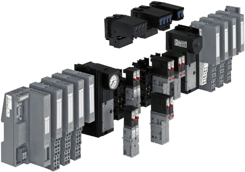
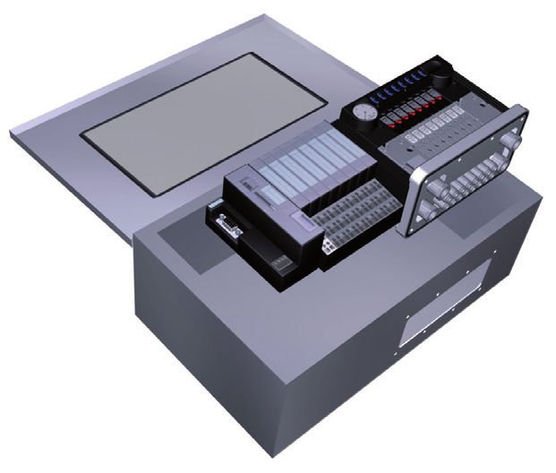
the max. permitted ambient temperature for the device. Fig. 1: Type 8644 AirLINE
Risk of electric shock!
• Before reaching into the device or the equipment, switch off the The Type 8644 AirLINE is an electrical and pneumatic automation
power supply and secure to prevent reactivation! system which was developed for use in the control cabinet or switch
• Observe applicable accident prevention and safety regulations for box. In a continuous system all electronic and pneumatic components
electrical equipment! are standardized, enabling pneumatic, electric and electronic modules
with various functions to be combined very easily with each other by
the observation of simple rules.
8 englishType 8644
Technical data
7. Technical data Nominal power 1W 2W
per valve (0.5 W nominal power (1 W nominal power
7.1. Conformity after 120 ms) after 120 ms)
The AirLINE system Type 8644 conforms to the EC Directives
Nominal current 43 mA 85 mA
according to the Declaration of Conformity.
per valve (28 mA holding current (52 mA holding current
7.2. Standards after 120 ms) after 120 ms)
The conformity with EC guidelines is guaranteed in accordance with 41 mA 41 mA
(when using Type 0460) (when using Type 0461)
standards:
• EN 61000-6-6, EN 61000-6-2, EN 61000-6-4, EN 61000-3-3, Ambient 0 ... +55 °C
EN 60079-0, EN 60079-15 temperature (when using Type 0460 and 0461: 0 ... +50 °C)
7.3. General Technical Data Storage -20 ... +60 °C
temperature
Technical Data Pilot valve type 0460, Pilot valve type 0461,
6524, 6525 6526, 6527 Protection class IP20 acc. to IEC 60529
IP65 in closed switch box
Add-on 11 mm 16.5 mm
dimension
Pressure range Vac. up to 10 bar Vac. up to 10 bar 7.4. Technical Data of Valves
Max. number of 64 32
Type Operating principle Add-on Flow-rate
valves (when using (when using
dimension (l/min)
Type 0460: 32) Type 0461: 24)
(mm)
Operating 24 V DC 24 V DC
voltage 6524 3/2-way valve 11 300
Voltage tolerance +20 % / -15 % +20 % / -15 % 2 x 3/2-way valve
(when using (when using 6525 5/2-way valve 11 300
Type 0460: ± 10 %) Type 0461: ± 10 %)
6526 3/2-way valve 16.5 700
Residual ripple 1 Vss 1 Vss
6527 5/2-way valve 16.5 700
english 9Type 8644
Technical data
0460 5/2-way impulse valve 11 200 7.4.2. Fluid connection
0460 5/3-way valve 11 200 Type 6524 Type 6525
0461 5/2-way impulse valve 16.5 450
0461 5/3-way valve 16.5 450 Design the pressure supply
with the largest possible
volume!
7.4.1. Rating plate X*
X* 5/R
3/R 4/A
Type 1/P
2/A 2/B
1/P 3/S
Operating principle X* - pilot control exhaust air
Orifice
Fig. 3: Fluid connection. Types 6524 and 6525
MADE IN GERMANY
6525 H 4,0
PN 2,5 - 7 bar 7.4.3. Fluid and electrical connection
24 V DC 1W Type 6524
450000Y W14UN (2 x 2/3-way valve)
- Pin coil 12 12 Observe pin
Identification number 14
controlled via bit 1 assignment!
Voltage (±10 %), capacity + Pin X* - pilot control
exhaust air
Pressure range - Pin coil 14 X*
controlled via bit 2 5/R
4/A
Fig. 2: Location and description of the rating plate 1/P Bit 1
2/B
3/S
Bit 2
Fig. 4: Fluid and electrical connection. Type 6524
10 englishType 8644
Structure and installation
8. Structure and installation Caution!
8.1. Safety instructions Escape of medium and malfunction!
Danger! If the seals are not seated correctly, leaks and malfunctions may occur
due to pressure losses.
Risk of injury from high pressure in the equipment! • Ensure that the seals are seated correctly in the area of the elec-
• Before loosening lines or valves, turn off the pressure and vent tronics and pneumatics.
the lines. Short-circuit, malfunction!
Risk of injury due to electrical shock! The electrical connection requires exact contacting.
• Before reaching into the device or the equipment, switch off the • Do not bend contacts.
power supply and secure to prevent reactivation!
• If connections are damaged or bent, replace the affected
• Observe applicable accident prevention and safety regulations components.
for electrical equipment!
• Do not switch on the system unless the components are in perfect
condition.
Warning! Note!
Risk of injury from improper assembly! Operate the system with direct current only!
• Installation may only be carried out by authorized technicians with To prevent damage to the system, use only direct current for the
the appropriate tools! system power supply.
Risk of injury from unintentional activation of the system and Prevent a pressure drop!
uncontrolled restart!
To prevent a pressure drop, design the system pressure supply with
• Secure system from unintentional activation. the largest possible volume.
• Following assembly, ensure a controlled restart.
english 11Type 8644
Structure and installation
8.2. Structure
Panel (optional pressure gauge to indicate operating pressure on the station)
Connection module on left 4-fold / 8-fold valve disc
2-fold valve disc
Intermediate feed
2-fold valve disc
Connection module on right
Working connections
Supply and vent connections
Fig. 5: Diagram of the modules of the Bürkert AirLINE system
12 englishType 8644
Structure and installation
8.3. Assembly 8.3.2. Installation of AirLINE Quick
8.3.1. Installation on standard rail To install AirLINE Quick, a notch must be first of all provided on the
base or the wall of the control cabinet, e.g. through lasing or punching.
Danger! For the dimensions of the relevant flange image, refer to chapter
Risk of electric shock! "8.3.3. Dimensions of the flange images for AirLINE Quick".
• Before reaching into the device or the equipment, switch off the Note!
power supply and secure to prevent reactivation!
The notch on the control cabinet base must be burr-free for the seal
of the AirLINE Quick adapter not to become damaged.
→→Place the valve terminal in the control cabinet on the prepared
notch.
Terminator
Converter
Converter
Field bus
Module
Module
Valve terminal
Type 8644
AirLINE Quick
adapter
Fig. 6: Installation of a valve block into a control cabinet
→→Fasten the standard rail firmly in the control cabinet.
→→Establish a short, wide PE connection between the standard rail
and the control cabinet. Control cabinet
The valve terminal must be freely accessible from above.
Ensure good heat dissipation! Fig. 7: Placing the valve terminal in the control cabinet
Recommended distance when installing in a control cabinet:
A 30 mm C 30 mm
B 30 mm D 60 mm
english 13Type 8644
Structure and installation
Note! 8.3.3. Dimensions of the flange images for
AirLINE Quick
The seal of the AirLINE Quick adapter must be placed into the
groove without being damaged before installing the adapter on the
158 ± 0.4
control cabinet base.
t >= 1.5 54 ± 0.3
→→Attach the stability plate from the outside to the control cabinet
base or wall to prevent distortion and fix with M5 screws.
59 ± 0.3
73 ± 0.3
(96)
6.5
R
Screws
Stability plate
155 ± 0.4 Space requirements
for reinforcing frame
(192) on the outside
Fig. 8: Attaching the stability plate
Fig. 9: Dimensions: 8-fold adapter
14 englishType 8644
Structure and installation
246 ± 0.4 279 ± 0.4
123 ± 0.4 140 ± 0.4
t >= 1.5 t >= 1.5
59 ± 0.3
73 ± 0.3
73 ± 0.3
59 ± 0.3
(96)
(96)
6.5 6.5
R R
243 ± 0.4 276 ± 0.4 Space require-
Space requirements
for reinforcing frame ments for rein-
(280) on the outside (313) forcing frame on
the outside
Fig. 10: Dimensions: 16-fold adapter Fig. 11: Dimensions: 16-fold adapter with intermediate feed module
english 15Type 8644
Structure and installation
8.4. Removing the valve block from the →→Lift the valve block vertically off the standard rail.
standard rail
There must be adequate space between valve block and pre-
Danger! decessor module > 6 mm.
Risk of electric shock! →→Detach the modules/terminals from the standard rail according to
• Before reaching into the device or the equipment, switch off the the manufacturer’s description.
power supply and secure to prevent reactivation.
Note!
The valve block is bolted securely onto the standard rail. Additional
electrical modules / terminals can be aligned in rows on the sides of The interface of the left connection module contains elements
the valve block. which may break off if force is used.
Procedure: • Never place the valve block on its side and observe the permitted
installation position.
→→Detach the adjacent modules/terminals (if fitted).
→→Release the attachment of the valve block on the standard rail. To
do this, turn the fastening screws all the way counter-clockwise.
Fig. 13: Detaching the modules/terminals from the standard rail
Fig. 12: Releasing the attachment of the valve block on the standard rail
16 englishType 8644
Installation
9. Installation 9.2. Fluid Installation
9.1. Safety instructions DANGER!
DANGER! Risk of injury from high pressure in the equipment!
• Before loosening lines or valves, turn off the pressure and vent
Risk of injury from high pressure in the equipment! the lines.
• Before loosening lines or valves, turn off the pressure and vent • Design the connections with the largest possible volume.
the lines.
• Close the open connections not required with lock screws.
Risk of injury due to electrical shock!
• The connections for the pilot control exhaust air (x) must not be
• Before reaching into the device or the equipment, switch off the sealed.
power supply and secure to prevent reactivation!
• Check correct assignment of the connections 1 and 3 or 5. They
• Observe applicable accident prevention and safety regulations may by no means be interchanged.
for electrical equipment!
9.2.1. Pneumatic connections - feed
Warning!
(R/S) 3/5
Risk of injury from improper installation!
Exhaust air
• Installation may only be carried out by authorized technicians with
the appropriate tools! X channel:
Standard version:
Risk of injury from unintentional activation of the system and Deaeration of the control valves
uncontrolled restart!
Control assist air version:
• Secure system from unintentional activation.
P connection for control valves
• Following installation, ensure a controlled restart.
(P) 1
Pressure supply connection
Fig. 14: Pneumatic Connections
english 17Type 8644
Installation
Procedure: 9.2.3. Pneumatic connections - valve discs
→→Depending on the version, plug the connections in the corre- Note!
sponding working connections (D10) or screw them in (G 1/4,
NPT 1/4). For 3/2-way valves the upper connections remain free.
Note! Inscription areas
For the plug-in connections the hose pipes must meet the following
requirements:
• Minimum hardness of 40 Shore D (in accordance with DIN
53505 or ISO 868);
• Outer diameter in accordance with DIN 73378 (max. permitted
deviation ± 0.1 mm of the nominal dimension);
• Burr-free, cut off at right angles and undamaged on the outer
diameter;
The hose pipes must be pressed all the way into the plug-in Working connec-
connections. tions for 5/2-way
valves
Working connec-
9.2.2. Removing the plug-in connections 8/4/2-fold valve discs tions for 3/2-way
→→To detach the pipes, press in the thrust ring and pull out the hose valves
pipe.
Fig. 15: Pneumatic connections - valve discs
5/2-way valve variants
Working connection Variant 1 Variant 2
Top (2) M7 D6, D1/4
Bottom (4) M7 D6, D1/4
18 englishType 8644
Start-Up
3/2-way valve variants 10. Start-Up
Working connection Variant 1 Variant 2 10.1. Safety instructions
Top (0) Sealed internally Sealed internally Warning!
Bottom (2) M7 D6, D1/4
Risk of injury from improper operation!
Procedure: Improper operation may result in injuries as well as damage to the
→→Depending on the version, plug the connections in the corre- device and the area around it.
sponding working connections (D6, D1/4) or screw them in (M7). • Before start-up, ensure that the operating personnel are familiar
→→Connection nipples can be used for threaded versions. with and completely understand the contents of the operating
instructions.
Inscription of the connections:
• Observe the safety instructions and intended use.
→→Label the inscription areas with the data of the valve • Only adequately trained personnel may start up the equipment/
connections.
the device.
10.2. Fluid start-up
9.3. Electrical Installation
Note!
DANGER!
• Switch on the supply pressure.
Risk of injury due to electrical shock! • Only then switch on the power supply!
• Before reaching into the device or the equipment, switch off the
power supply and secure to prevent reactivation!
Procedures before fluid start-up:
The electrical installation of the AirLINE system corresponds to the →→Check connections, voltage and operating pressure.
installation of the decentralized peripheral device (depending on the →→Ensure that max. operating data are not exceeded.
relevant cooperation partner Siemens, Wago, Phoenix or Rockwell).
→→Check correct assignment of the connections 1 and 3 or 5. They
Refer to the manuals provided by the cooperation partners for a more may by no means be interchanged.
detailed description.
→→Release manual actuation during electrical operation.
english 19Type 8644
Transport, Storage, Disposal
10.3. Electrical start-up 11. Transport, Storage, Disposal
The start-up of the AirLINE system corresponds to the installation of the Note!
decentralized peripheral device (depending on the relevant cooperation
partner Siemens, Wago, Phoenix or Rockwell). Transport damages!
Refer to the manuals provided by the cooperation partners for a more Inadequately protected equipment may be damaged during transport.
detailed description. • During transportation protect the device against wet and dirt in
shock-resistant packaging.
• Avoid exceeding or dropping below the permitted storage
temperature.
Incorrect storage may damage the device!
• Store the device in a dry and dust-free location!
• Storage temperature: -20 ... +60 °C.
Damage to the environment caused by device components
contaminated with media!
• Ensure the device and packaging are disposed of in an environ-
mentally sound manner.
• Observe applicable regulations relating to refuse disposal and
the environment.
• Observe the national waste disposal regulations.
20 englishTyp 8644
Inhaltsverzeichnis
1. Der Quickstart........................................................................................ 22 9. Installation................................................................................................ 35
9.1. Sicherheitshinweise........................................................................35
2. Darstellungsmittel........................................................................... 22 9.2. Fluidische Installation.....................................................................35
9.3. Elektrische Installation....................................................................37
3. BestimmungsgemäSSe Verwendung2����������������������������������� 23
3.1. Vorhersehbarer Fehlgebrauch......................................................23 10. Inbetriebnahme.................................................................................... 37
10.1. Sicherheitshinweise.....................................................................37
4. Grundlegende Sicherheitshinweise.................................. 24
10.2. Fluidische Inbetriebnahme..........................................................37
5. Allgemeine Hinweise........................................................................... 25 10.3. Elektrische Inbetriebnahme........................................................38
5.1. Kontaktadresse................................................................................25 11. Transport, Lagerung, Verpackung................................... 38
5.2. Gewährleistung...............................................................................25
5.3. Informationen im Internet...............................................................25
6. Systembeschreibung........................................................................ 26
6.1. Einsatzbereich..................................................................................26
6.2. Beschreibung des Systems..........................................................26
7. Technische Daten................................................................................. 27
7.1. Konformität........................................................................................27
7.2. Normen..............................................................................................27
7.3. Allgemeine technische Daten.......................................................27
7.4. Technische Daten Ventile..............................................................27
8. Aufbau und Montage......................................................................... 29
8.1. Sicherheitshinweise........................................................................29
8.2. Aufbau................................................................................................30
8.3. Montage............................................................................................31
8.4. Entfernen des Ventilblocks von der Normschiene...................34
deutsch 21Typ 8644
Der Quickstart
1. Der Quickstart 2. Darstellungsmittel
Der Quickstart beschreibt den gesamten Lebenszyklus des Gerätes. In dieser Anleitung werden folgende Darstellungsmittel verwendet.
Bewahren Sie diese Anleitung so auf, dass sie für jeden Benutzer gut
Gefahr!
zugänglich ist und jedem neuen Eigentümer des Gerätes wieder zur
Verfügung steht. Warnt vor einer unmittelbaren Gefahr!
• Bei Nichtbeachtung sind Tod oder schwere Verletzungen die
Wichtige Informationen zur Sicherheit! Folge.
Lesen Sie den Quickstart sorgfältig durch. Beachten Sie vor allem
die Kapitel „Grundlegende Sicherheitshinweise“ und „Bestimmungs- Warnung!
gemäße Verwendung“. Warnt vor einer möglicherweise gefährlichen Situation!
• Der Quickstart muss gelesen und verstanden werden. • Bei Nichtbeachtung können schwere Verletzungen oder Tod die
Folge sein.
Der Quickstart erläutert beispielhaft die Montage und Inbetriebnahme Vorsicht!
des Gerätes.
Die ausführliche Beschreibung des Gerätes finden Sie in der Bedie- Warnt vor einer möglichen Gefährdung!
nungsanleitung für den Typ 8644. • Nichtbeachtung kann mittelschwere oder leichte Verletzungen
zur Folge haben.
Die Bedienungsanleitung finden Sie auf der beigelegten CD
oder im Internet unter: Hinweis!
www.buerkert.de Warnt vor Sachschäden!
Wichtige Tipps und Empfehlungen.
Verweist auf Informationen in dieser Bedienungsanleitung
oder in anderen Dokumentationen.
→→markiert einen Arbeitsschritt den Sie ausführen müssen.
22 deutschTyp 8644
Bestimmungsgemäße Verwendung
3. BestimmungsgemäSSe 3.1. Vorhersehbarer Fehlgebrauch
Verwendung • In die Medienanschlüsse des Systems keine aggressiven oder
brennbaren Medien einspeisen.
Bei nicht bestimmungsgemäßem Einsatz der AirLINE Typ 8644
können Gefahren für Personen, Anlagen in der Umgebung und • Das Gehäuse nicht mechanisch belasten (z. B. durch Ablage von
die Umwelt entstehen. Gegenständen oder als Trittstufe).
• Das Gerät ist für den Einsatz in explosionsgefährdeten Umgebun- • Beachten, dass in Systemen, die unter Druck stehen, Leitungen und
gen konzipiert (nur Typ 8644 Siemens und Wago). Es darf zur Ventile nicht gelöst werden dürfen.
Steuerung pneumatisch betriebener Geräte eingesetzt werden. • Vor Eingriffen in das System in jedem Fall die Spannung abschalten.
• Das Gerät nicht ungeschützt im Außenbereich einsetzen.
• Druckversorgung möglichst großvolumig ausführen, um Druckabfall
• Für den Einsatz die in den Vertragsdokumenten und der Bedie- beim Schalten zu vermeiden.
nungsanleitung spezifizierten zulässigen Daten, Betriebs- und
Einsatzbedingungen beachten. Diese sind im Kapitel „Technische
Daten“ beschrieben.
• Das Gerät nur in Verbindung mit von Bürkert empfohlenen bzw.
zugelassenen Fremdgeräten und -komponenten einsetzen.
• Voraussetzungen für den sicheren und einwandfreien Betrieb sind
sachgemäßer Transport, sachgemäße Lagerung und Installation
sowie sorgfältige Bedienung und Instandhaltung.
• Setzen Sie das Gerät nur bestimmungsgemäß ein.
deutsch 23Typ 8644
Grundlegende Sicherheitshinweise
4. Grundlegende Allgemeine Gefahrensituationen.
Sicherheitshinweise Zum Schutz vor Verletzungen ist zu beachten:
Diese Sicherheitshinweise berücksichtigen keine • Dass die Anlage nicht unbeabsichtigt betätigt werden kann.
• Zufälligkeiten und Ereignisse, die bei Montage, Betrieb und Wartung • Installations- und Instandhaltungsarbeiten dürfen nur von auto-
der Geräte auftreten können. risiertem Fachpersonal mit geeignetem Werkzeug ausgeführt
werden.
• ortsbezogenen Sicherheitsbestimmungen, für deren Einhaltung, auch
in Bezug auf das Montagepersonal, der Betreiber verantwortlich • Nach einer Unterbrechung der elektrischen oder pneumatischen
ist. Versorgung ist ein definierter oder kontrollierter Wiederanlauf des
Prozesses zu gewährleisten.
• Das Gerät darf nur in einwandfreiem Zustand und unter Beachtung
der Bedienungsanleitung betrieben werden.
Gefahr durch hohen Druck! • Für die Einsatzplanung und den Betrieb des Gerätes müssen die
• Vor dem Lösen von Leitungen oder Ventilen den Druck abschalten allgemeinen Regeln der Technik eingehalten werden.
und Leitungen entlüften.
Gefahr durch elektrische Spannung!
Der Typ 8644 AirLINE wurde unter Einbeziehung der aner-
• Vor Eingriffen in das Gerät oder die Anlage, Spannung abschalten kannten sicherheitstechnischen Regeln entwickelt und ent-
und vor Wiedereinschalten sichern!
spricht dem Stand der Technik. Trotzdem können Gefahren
• Die geltenden Unfallverhütungs- und Sicherheitsbestimmungen entstehen.
für elektrische Geräte beachten!
Bei Nichtbeachtung dieser Bedienungsanleitung und ihrer Hinweise
Verbrennungsgefahr/Brandgefahr bei Dauerbetrieb durch heiße
sowie bei unzulässigen Eingriffen in das Gerät entfällt jegliche Haf-
Geräteoberfläche!
tung unsererseits, ebenso erlischt die Gewährleistung auf Geräte
• Das Gerät von leicht brennbaren Stoffen und Medien fernhalten und Zubehörteile!
und nicht mit bloßen Händen berühren.
24 deutschTyp 8644
Allgemeine Hinweise
Hinweis! 5. Allgemeine Hinweise
System nur mit Gleichstrom betreiben! 5.1. Kontaktadresse
Um Schäden am System zu vermeiden, für die Stromversorgung Deutschland
des Systems ausschließlich Gleichstrom einsetzen. Bürkert Fluid Control Systems
Druckabfall vermeiden! Sales Center
Um einen Druckabfall zu vermeiden, die Druckversorgung des Christian-Bürkert-Str. 13-17
Systems möglichst großvolumig ausführen. D-74653 Ingelfingen
Tel. + 49 (0) 7940 - 10 91 111
Elektrostatisch gefährdete Bauelemente / Baugruppen!
Fax + 49 (0) 7940 - 10 91 448
Das Gerät enthält elektronische Bauelemente, die gegen elektrosta- E-mail: info@de.buerkert.com
tische Entladung (ESD) empfindlich reagieren. Berührung mit elek-
trostatisch aufgeladenen Personen oder Gegenständen gefährdet International
diese Bauelemente. Im schlimmsten Fall werden sie sofort zerstört Die Kontaktadressen finden Sie auf den letzten Seiten der
oder fallen nach der Inbetriebnahme aus. gedruckten Bedienungsanleitung.
• Beachten Sie die Anforderungen nach EN 61340-5-1 und 5-2, Außerdem im Internet unter: www.burkert.com
um die Möglichkeit eines Schadens durch schlagartige elektro-
statische Entladung zu minimieren bzw. zu vermeiden!
5.2. Gewährleistung
• Achten Sie ebenso darauf, dass Sie elektronische Bauelemente
nicht bei anliegender Versorgungsspannung berühren! Voraussetzung für die Gewährleistung ist der bestimmungsgemäße
Gebrauch der AirLINE Typ 8644 unter Beachtung der spezifizierten
Einsatzbedingungen.
5.3. Informationen im Internet
Bedienungsanleitungen und Datenblätter zum Typ 8644 finden Sie im
Internet unter: www.buerkert.de
deutsch 25Typ 8644
Systembeschreibung
6. Systembeschreibung 6.2. Beschreibung des Systems
6.1. Einsatzbereich
Das System AirLINE ist für den dezentralen Einsatz in Industrieum-
gebungen konzipiert. Elektronik und Fluidik können dabei durch den
modularen Aufbau besonders einfach und effizient kombiniert werden.
Gefahr!
Explosionsgefahr!
Bei Systemen im explosionsgeschützten Bereich (Typ 8644 Siemens
und Wago) die in einem Schaltschrank eingesetzt sind, muss fol-
gendes sichergestellt sein:
• Der Schaltschrank muss für den Einsatz im explosionsgeschütz-
ten Bereich zugelassen sein.
• Der Schaltschrank muss so groß dimensioniert werden, dass
die entstehende Verlustwärme in geeigneter Weise nach außen
abgeführt werden kann.
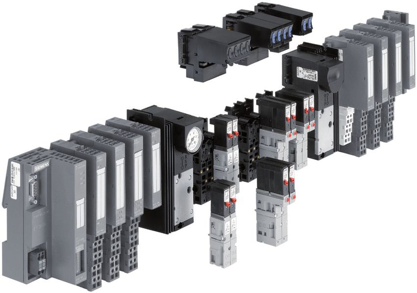
• Die Innentemperatur des Schaltschrankes darf die max. zulässige Bild 1: Typ 8644 AirLINE
Umgebungstemperatur für das Gerät nicht überschreiten.
Gefahr durch elektrische Spannung! Der Typ 8644 AirLINE ist ein elektrisches und pneumatisches Auto-
• Vor Eingriffen in das Gerät oder die Anlage, Spannung abschalten matisierungssystem, das für den Einsatz im Schaltschrank oder
und vor Wiedereinschalten sichern! Schaltkasten entwickelt wurde. In einem durchgängigen System sind
• Die geltenden Unfallverhütungs- und Sicherheitsbestimmungen alle elektronischen und pneumatischen Komponenten vereinheitlicht,
für elektrische Geräte beachten! so dass unter Beachtung einfacher Regeln pneumatische, elektrische
und elektronische Module unterschiedlicher Funktionalität sehr einfach
miteinander kombiniert werden können.
26 deutschTyp 8644
Technische Daten
7. Technische Daten Nennleistung je 1W 2W
Ventil (0,5 W Nennleistung (1 W Nennleistung
7.1. Konformität
nach 120 ms) nach 120 ms)
Das AirLINE System Typ 8644 ist konform zu den EG-Richtlinien
entsprechend der Konformitätserklärung. Nennstrom je 43 mA 85 mA
Ventil (28 mA Haltestrom (52 mA Haltestrom
7.2. Normen nach 120 ms) nach 120 ms)
Durch folgende Normen wird die Konformität mit den EG-Richtlinien 41 mA 41 mA
erfüllt: (bei Verwendung des (bei Verwendung des
• EN 61000-6-6, EN 61000-6-2, EN 61000-6-4, EN 61000-3-3, Typs 0460) Typs 0461)
EN 60079-0, EN 60079-15 Umgebungs- 0 ... +55 °C
temperatur (bei Verwendung des Typs 0460 und 0461:
7.3. Allgemeine technische Daten 0 ... +50 °C)
Technische Pilotventil Typ 0460, Pilotventil Typ 0461, Lagertemperatur -20 ... +60 °C
Daten 6524, 6525 6526, 6527 Schutzart IP20 nach IEC 60529
Anreihmaß 11 mm 16,5 mm IP65 in geschlossenem Schaltkasten
Druckbereich Vak. bis 10 bar Vak. bis 10 bar
Max. Anzahl 64 32 7.4. Technische Daten Ventile
Ventile (bei Verwendung des (bei Verwendung des
Typs 0460: 32) Typs 0461: 24) Typ Wirkungsweise Anreihmaß Durchfluss
(mm) (l/min)
Betriebs- 24 V DC 24 V DC
spannung 6524 3/2-Wege Ventil 11 300
Spannungsto- +20 % / -15 % +20 % / -15 % 2 x 3/2-Wege Ventil
leranz (bei Verwendung des (bei Verwendung des 6525 5/2-Wege Ventil 11 300
Typs 0460: ± 10 %) Typs 0461: ± 10 %)
6526 3/2-Wege Ventil 16,5 700
Restwelligkeit 1 Vss 1 Vss
6527 5/2-Wege Ventil 16,5 700
deutsch 27Typ 8644
Technische Daten
0460 5/2-Wege Impulsventil 11 200 7.4.2. Fluidischer Anschluss
0460 5/3-Wege Ventil 11 200 Typ 6524 Typ 6525
0461 5/2-Wege Impulsventil 16,5 450
0461 5/3-Wege Ventil 16,5 450 Druckversorgung möglichst
großvolumig ausführen!
7.4.1. Typenschild X*
X* 5/R
3/R 4/A
Typ 1/P
2/A 2/B
1/P 3/S
Wirkungsweise X* - Vorsteuerabluft
Nennweite Bild 3: Fluidischer Anschluss. Typen 6524 und 6525
7.4.3. luidischer und elektrischer
F
MADE IN GERMANY
6525 H 4,0
PN 2,5 - 7 bar Anschluss
24 V DC 1W
Typ 6524
450000Y W14UN
(2 x 2/3-Wege Ventil)
-Pol Spule 12 12 Pinbelegung
Identnummer 14
angesteuert über Bit 1 beachten!
Spannung (± 10 %), Leistung +Pol X* - Vorsteuerabluft
Druckbereich -Pol Spule 14 X*
angesteuert über Bit 2 5/R
Bild 2: Lage und Beschreibung des Typenschildes 4/A
1/P Bit 1
2/B
3/S
Bit 2
Bild 4: Fluidischer und elektrischer Anschluss. Typ 6524
28 deutschTyp 8644
Aufbau und Montage
8. Aufbau und Montage Vorsicht!
8.1. Sicherheitshinweise Mediumsaustritt und Fehlfunktion!
Gefahr! Bei mangelhaftem Sitz der Dichtungen können Undichtigkeiten und
Funktionsbeeinträchtigungen durch Druckverluste auftreten.
Verletzungsgefahr durch hohen Druck in der Anlage! • Auf korrekten Sitz der Dichtungen im Bereich der Elektronik und
• Vor dem Lösen von Leitungen oder Ventilen den Druck abschalten Pneumatik achten.
und Leitungen entlüften. Kurzschluss, Funktionsausfall!
Verletzungsgefahr durch Stromschlag! Der elektrische Anschluss erfordert exakte Kontaktierung.
• Vor Eingriffen in das Gerät oder die Anlage, Spannung abschalten • Kontakte nicht verbiegen.
und vor Wiedereinschalten sichern!
• Bei beschädigten oder verbogenen Anschlüssen die betroffenen
• Die geltenden Unfallverhütungs- und Sicherheitsbestimmungen Komponenten austauschen.
für elektrische Geräte beachten!
• Das System nur bei einwandfreiem Zustand der Komponenten
einschalten.
Warnung!
Hinweis!
Verletzungsgefahr bei unsachgemäßer Montage!
• Die Montage darf nur autorisiertes Fachpersonal mit geeignetem System nur mit Gleichstrom betreiben!
Werkzeug durchführen! Um Schäden am System zu vermeiden, für die Stromversorgung des
Verletzungsgefahr durch ungewolltes Einschalten der Anlage Systems ausschließlich Gleichstrom einsetzen.
und unkontrollierten Wiederanlauf! Druckabfall vermeiden!
• Anlage vor unbeabsichtigtem Betätigen sichern. Um einen Druckabfall zu vermeiden, die Druckversorgung des
• Nach der Montage einen kontrollierten Wiederanlauf Systems möglichst großvolumig ausführen.
gewährleisten.
deutsch 29Typ 8644
Aufbau und Montage
8.2. Aufbau
Blende (optional Manometer zur Betriebsdruckanzeige an der Station)
Anschlussmodul links 4-fach / 8-fach Ventilscheibe
2-fach Ventilscheibe
Zwischeneinspeisung
2-fach Ventilscheibe
Anschlussmodul rechts
Arbeitsanschlüsse
Versorgungs- und Entlüftungsanschlüsse
Bild 5: Darstellung der Module des Bürkert AirLINE-Systems
30 deutschTyp 8644
Aufbau und Montage
8.3. Montage 8.3.2. Montage AirLINE Quick
8.3.1. Montage auf der Normschiene Zur Montage von AirLINE Quick muss zuerst ein Ausbruch am Schalt-
schrankboden bzw. der Schaltschrankwand vorgesehen werden. Dies
Gefahr! kann z. B. durch Lasern oder Stanzen erfolgen.
Gefahr durch elektrische Spannung! Die Abmessungen des entsprechenden Flanschbildes siehe Kapitel
„8.3.3. Abmessungen der Flanschbilder für AirLINE Quick“.
• Vor Eingriffen in das Gerät oder die Anlage, Spannung abschalten
und vor Wiedereinschalten sichern! Hinweis!
Der Ausbruch am Schaltschrankboden muss gratfrei sein, damit
die Dichtung des AirLINE Quick Adapters nicht beschädigt wird.
→→Die Ventilinsel im Schaltschrank auf den vorbereiteten Ausbruch
platzieren.
Abschluss
Umsetzer
Umsetzer
Feldbus
Modul
Modul
Ventilinsel
Typ 8644
AirLINE Quick
Adapter
Bild 6: Einbau des Ventilblocks in einen Schaltschrank
→→Die Normschiene fest im Schaltschrank montieren.
→→Eine kurze, breite PE-Verbindung zwischen Normschiene und
Schaltschrank herstellen.
Die Ventilinsel muss nach oben frei zugänglich sein. Schaltschrank
Für gute Wärmeabfuhr sorgen!
Bild 7: Platzieren der Ventilinsel im Schaltschrank
Abstandsempfehlung beim Einbau in den Schaltschrank:
A 30 mm C 30 mm
B 30 mm D 60 mm
deutsch 31Typ 8644
Aufbau und Montage
Hinweis! 8.3.3. Abmessungen der Flanschbilder für
AirLINE Quick
Die Dichtung des AirLINE Quick Adapters muss beschädigungsfrei
in die Nut eingelegt werden, bevor der Adapter am Schaltschrank-
158 ± 0,4
boden montiert werden kann.
t >= 1,5 54 ± 0,3
→→Von Außen das Stabilisierungsblech zur Vermeidung von Ver-
werfungen am Schaltschrankboden oder der Schaltschrankwand
anbringen und mit Schrauben M5 befestigen.
59 ± 0,3
73 ± 0,3
(96)
6,5
R
Schrauben
Stabilisierungsblech 155 ± 0,4 Platzbedarf für
Versteifungsrahmen
(192) auf Außenseite
Bild 8: Befestigung des Stabilisierungsblechs Bild 9: Abmessungen: 8-fach Adapter
32 deutschTyp 8644
Aufbau und Montage
246 ± 0,4 279 ± 0,4
123 ± 0,4 140 ± 0,4
t >= 1,5 t >= 1,5
59 ± 0,3
73 ± 0,3
73 ± 0,3
59 ± 0,3
(96)
(96)
6,5 6,5
R R
243 ± 0,4 276 ± 0,4 Platzbedarf für
Platzbedarf für
Versteifungs-
Versteifungsrahmen
(280) (313) rahmen auf
auf Außenseite
Außenseite
Bild 10: Abmessungen: 16-fach Adapter Bild 11: Abmessungen: 16-fach Adapter mit Zwischeneinspeisemodul
deutsch 33Typ 8644
Aufbau und Montage
8.4. Entfernen des Ventilblocks von der →→Ventilblock senkrecht von der Normschiene abheben.
Normschiene
Es muss genügend Platz zwischen Ventilblock und Vorgänger-
Gefahr! modul sein > 6 mm.
Gefahr durch elektrische Spannung! →→Module/Klemmen entsprechend der Herstellerbeschreibung von
• Vor Eingriffen in das Gerät oder die Anlage, Spannung abschal- der Normschiene lösen.
ten und vor Wiedereinschalten sichern.
Hinweis!
Der Ventilblock ist fest auf der Normschiene verschraubt. An seinen
Seiten können weitere elektrische Module/Klemmen angereiht sein. Die Schnittstelle des linken Anschlussmoduls beinhaltet Elemente,
die bei Gewalteinwirkung abbrechen können.
Vorgehensweise:
• Ventilblock nie auf die Seite stellen und zulässige Einbaulage
→→Die benachbarten Module/Klemmen (falls vorhanden) lösen. beachten.
→→Befestigung des Ventilblocks an der Normschiene entriegeln.
Hierzu die Befestigungsschrauben gegen den Uhrzeigersinn bis
zum Anschlag drehen.
Bild 13: Lösen der Modulen/Klemmen von der Normschiene
Bild 12: Entriegeln die Befestigung des Ventilblocks an der Normschiene
34 deutschTyp 8644
Installation
9. Installation 9.2. Fluidische Installation
9.1. Sicherheitshinweise GEFAHR!
GEFAHR! Verletzungsgefahr durch hohen Druck in der Anlage!
• Vor dem Lösen von Leitungen oder Ventilen den Druck abschalten
Verletzungsgefahr durch hohen Druck in der Anlage! und Leitungen entlüften.
• Vor dem Lösen von Leitungen oder Ventilen den Druck abschalten • Die Anschlüsse möglichst großvolumig ausführen.
und Leitungen entlüften.
• Nicht benötigte, offene Anschlüsse mit Verschlussschrauben
Verletzungsgefahr durch Stromschlag! schließen.
• Vor Eingriffen in das Gerät oder die Anlage, Spannung abschalten • Die Anschlüsse für die Vorsteuerabluft (x) dürfen nicht verschlos-
und vor Wiedereinschalten sichern! sen werden.
• Die geltenden Unfallverhütungs- und Sicherheitsbestimmungen • Die vorschriftsmäßige Belegung der Anschlüsse 1 und 3 bzw. 5
für elektrische Geräte beachten! überprüfen. Diese dürfen auf keinen Fall vertauscht werden.
Warnung! 9.2.1. Pneumatische Anschlüsse
- Einspeisung
Verletzungsgefahr bei unsachgemäßer Installation!
• Die Installation darf nur autorisiertes Fachpersonal mit geeignetem (R/S) 3/5
Werkzeug durchführen!
Abluft
Verletzungsgefahr durch ungewolltes Einschalten der Anlage X-Kanal:
und unkontrollierten Wiederanlauf! Standardausführung:
• Anlage vor unbeabsichtigtem Betätigen sichern. Entlüftung der Steuerventile
• Nach der Installation einen kontrollierten Wiederanlauf Steuerhilfsluftausführung:
gewährleisten. P-Anschluss für Steuerventile
(P) 1
Druckversorgungsanschluss
Bild 14: Pneumatische Anschlüsse
deutsch 35Typ 8644
Installation
Vorgehensweise: 9.2.3. Pneumatische Anschlüsse
→→Die Anschlüsse je nach Ausführung an den entsprechenden - Ventilscheiben
Arbeitsanschlüssen einstecken (D10) oder einschrauben (G 1/4, Hinweis!
NPT 1/4).
Bei 3/2-Wege Ventilen bleiben die oberen Anschlüsse frei.
Hinweis!
Beschriftungsfelder
Für die Steckanschlüsse müssen die Schlauchleitungen folgende
Anforderungen erfüllen:
• Mindesthärte von 40 Shore D (nach DIN 53505 bzw. ISO 868);
• Außendurchmesser entsprechend DIN 73378 (max. zul. Abwei-
chung ± 0,1 mm vom Nennmaß);
• Gratfrei, rechtwinklig abgeschnitten und am Außendurchmesser
unbeschädigt;
Die Schlauchleitungen sind bis zum Anschlag in die Steckanschlüsse
einzudrücken.
Arbeitsanschlüsse
bei 5/2-Wege
9.2.2. Demontage der Steckanschlüsse Ventilen
→→Zum Lösen der Leitungen den Druckring eindrücken und die Arbeitsanschlüsse
Schlauchleitung herausziehen. 8/4/2-fach Ventilscheiben bei 3/2-Wege
Ventilen
Bild 15: Pneumatische Anschlüsse - Ventilscheiben
Varianten 5/2-Wege Ventile
Arbeitsanschluss Variante 1 Variante 2
Oben (2) M7 D6, D1/4
Unten (4) M7 D6, D1/4
36 deutschTyp 8644
Inbetriebnahme
Varianten 3/2-Wege Ventile 10. Inbetriebnahme
Arbeitsanschluss Variante 1 Variante 2 10.1. Sicherheitshinweise
Oben (0) Intern verschlossen Intern verschlossen Warnung!
Unten (2) M7 D6, D1/4
Verletzungsgefahr bei unsachgemäßem Betrieb!
Vorgehensweise: Nicht sachgemäßer Betrieb kann zu Verletzungen, sowie Schäden
→→Die Anschlüsse je nach Ausführung an den entsprechenden am Gerät und seiner Umgebung führen.
Arbeitsanschlüssen einstecken (D6, D1/4) oder einschrauben (M7). • Vor der Inbetriebnahme muss gewährleistet sein, dass der Inhalt
→→Bei Gewindeausführung können Anschlussnippel verwendet der Bedienungsanleitung dem Bedienungspersonal bekannt ist
werden. und vollständig verstanden wurde.
Beschriftung der Anschlüsse: • Die Sicherheitshinweise und die bestimmungsgemäße Verwen-
dung müssen beachtet werden.
→→Die Beschriftungsfelder mit den Daten der Ventilanschlüsse • Nur ausreichend geschultes Personal darf die Anlage/das Gerät
beschriften. in Betrieb nehmen.
10.2. Fluidische Inbetriebnahme
9.3. Elektrische Installation
Hinweis!
GEFAHR!
• Schalten Sie den Versorgungsdruck ein.
Verletzungsgefahr durch Stromschlag! • Schalten Sie erst danach die Spannung ein!
• Vor Eingriffen in das Gerät oder die Anlage, Spannung abschalten
und vor Wiedereinschalten sichern!
Maßnahmen vor der fluidischen Inbetriebnahme:
Die elektrische Installation des AirLINE Systems entspricht der Ins- →→Anschlüsse, Spannung und Betriebsdruck überprüfen.
tallation des dezentralen Peripheriegerätes (abhängig vom jeweiligen →→Beachten, dass max. Betriebsdaten nicht überschritten werden.
Kooperationspartner Siemens, Wago, Phoenix oder Rockwell). →→Die vorschriftsmäßige Belegung der Anschlüsse 1 und 3 bzw. 5
Alle hier notwendigen Schritte sind den jeweiligen Handbücher der überprüfen. Diese dürfen auf keinen Fall vertauscht werden.
Kooperationspartner zu entnehmen. →→Bei elektrischem Betrieb die Handbetätigung entriegeln.
deutsch 37Typ 8644
Transport, Lagerung, Verpackung
10.3. Elektrische Inbetriebnahme 11. Transport, Lagerung,
Die Inbetriebnahme des AirLINE Systems entspricht der Installation Verpackung
des dezentralen Peripheriegerätes (abhängig vom jeweiligen Koope-
Hinweis!
rationspartner Siemens, Wago, Phoenix oder Rockwell).
Alle hier notwendigen Schritte sind den jeweiligen Handbüchern der Transportschäden!
Kooperationspartner zu entnehmen. Unzureichend geschützte Geräte können durch den Transport
beschädigt werden.
• Gerät vor Nässe und Schmutz geschützt in einer stoßfesten
Verpackung transportieren.
• Eine Über- bzw. Unterschreitung der zulässigen Lagertempe-
ratur vermeiden.
Falsche Lagerung kann Schäden am Gerät verursachen!
• Gerät trocken und staubfrei lagern!
• Lagertemperatur: -20 ... +60 °C.
Umweltschäden durch von Medien kontaminierte Geräteteile!
• Gerät und Verpackung umweltgerecht entsorgen!
• Geltende Entsorgungsvorschriften und Umweltbestimmungen
einhalten.
• Die nationalen Abfallbeseitigungsvorschriften beachten.
38 deutschType 8644
Sommaire
1. Quickstart................................................................................................... 40 9. Installation................................................................................................ 53
9.1. Consignes de sécurité...................................................................53
2. Symboles....................................................................................................... 40 9.2. Installation fluidique........................................................................53
9.3. Installation électrique......................................................................55
3. Utilisation conforme....................................................................... 41
3.1. Mauvaise utilisation prévisible......................................................41 10. Mise en service..................................................................................... 55
10.1. Consignes de sécurité.................................................................55
4. Consignes de sécurité générales...................................... 42
10.2. Mise en service fluidique.............................................................55
5. Indications générales..................................................................... 43 10.3. Mise en service électrique..........................................................56
5.1. Adresse.............................................................................................43 11. Transport, Stockage, Élimination...................................... 56
5.2. Garantie légale.................................................................................43
5.3. Information sur Internet..................................................................43
6. Description du système................................................................. 44
6.1. Utilisation...........................................................................................44
6.2. Description du système.................................................................44
7. Caractéristiques techniques................................................. 45
7.1. Conformité........................................................................................45
7.2. Normes..............................................................................................45
7.3. Caractéristiques techniques générales.....................................45
7.4. Caractéristiques techniques vannes..........................................45
8. Structure et montage..................................................................... 47
8.1. Consignes de sécurité...................................................................47
8.2. Structure...........................................................................................48
8.3. Montage............................................................................................49
8.4. Retrait du bloc de vannes du rail normalisé..............................52
français 39Vous pouvez aussi lire