Type 8640 AirLINE - Quickstart Deutsch Français
←
→
Transcription du contenu de la page
Si votre navigateur ne rend pas la page correctement, lisez s'il vous plaît le contenu de la page ci-dessous
Type 8640
AirLINE

Quickstart

English   Deutsch   Français
We reserve the right to make technical changes without notice.
Technische Änderungen vorbehalten.
Sous réserve de modifications techniques.

© 2009 - 2012 Bürkert Werke GmbH

Operating Instructions 1208/10_EU-ML_00804431 / Original DE
Type 8640
                                                        Contents

1. QUICKSTART......................................................................................................4   6. ASSEMBLY...........................................................................................................8
   1.1. Definition of the Term “Device”...................................................... 4                           6.1. Safety instructions............................................................................ 8
   1.2. Symbols............................................................................................... 4          6.2. Assembly............................................................................................. 9

2. INTENDED USE.................................................................................................5      7. INSTALLATION................................................................................................ 12
   2.1. Restrictions......................................................................................... 5           7.1. Fluid Installation...............................................................................12
                                                                                                                          7.2. Fluid deinstallation..........................................................................15
3. GENERAL SAFETY INFORMATION.........................................................5                                   7.3. Electrical Installation.......................................................................15
4. GENERAL INFORMATION............................................................................6                    8. START-UP.......................................................................................................... 19
   4.1. Contact address................................................................................ 6
   4.2. Warranty.............................................................................................. 6       9. MAINTENANCE............................................................................................... 19
   4.3. Informations in the Internet.............................................................. 6
                                                                                                                       10. TRANSPORT, STORAGE, DISPOSAL............................................... 19
5. TECHNICAL DATA............................................................................................7
   5.1. Conformity.......................................................................................... 7
   5.2. Standards............................................................................................ 7
   5.3. General Technical Data................................................................... 7

                                                                                                                                                                      english                                                              3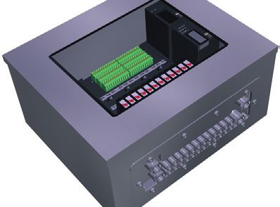
Type 8640
Quickstart
1. QUICKSTART 1.2. Symbols
The operating instructions describe the entire life cycle of the device. The following symbols are used in these instructions.
Keep these instructions in a location which is easily accessible to
DANGER!
every user and make these instructions available to every new owner
of the device. Warns of an immediate danger!
• Failure to observe the warning may result in a fatal or serious
Important Safety Information! injury.
Read Quickstart carefully and thoroughly. Study in particular the
chapters entitled “General safety information” and “Intended use”. WARNING!
• Quickstart must be read and understood. Warns of a potentially dangerous situation!
• Failure to observe the warning may result in serious injuries or death.
The Quickstart explains, for example, how to install and start-up the
device. A detailed description of the device can be found in the oper- CAUTION!
ating instructions for Type 8640.
Warns of a possible danger!
The operating instructions can be found on the enclosed CD • Failure to observe this warning may result in a moderately severe
and on the Internet at: or minor injury.
www.burkert.com
NOTE!
1.1. Definition of the Term “Device” Warns of damage to property!
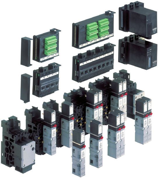
In these instructions, the term “device” always refers to the system
AirLINE Type 8640.
Important tips and recommendations.
Refers to information in these operating instructions or in
other documentation.
→→designates a procedure which you must carry out.
4 english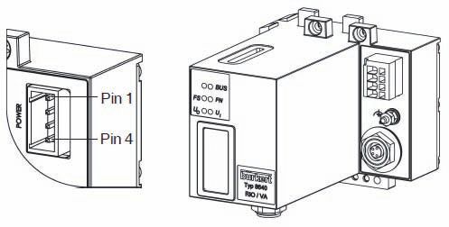
Type 8640
                             Intended use

2.     INTENDED USE                                                       3.     GENERAL SAFETY INFORMATION
 Non-intended use of the AirLINE Type 8640 may be a hazard to             This safety information does not cover:
 people, nearby equipment and the environment.                            • Haphazard situations that can arise during installation, operation and
 • The device may be used for the control of pneumatically oper-            maintenance of the use.
   ated units.                                                            • Locally applicable safety regulations which the operator and instal-
 • Do not use the device outdoors unprotected.                              lation personnel are obligated to follow.
 • Do not physically stress the housing (e.g. by placing objects on
                                                                           General Hazardous Situations.
   it or standing on it).
                                                                           To prevent injuries:
 • Use according to the authorized data, service and operating condi-
   tions specified in the contract documents and operating instruc-        • Ensure that the system cannot be activated unintentionally.
   tions. These are described in the chapter entitled “Technical data”.    • Note that pipes and valves must not become detached in systems
 • The device may be used only in conjunction with third-party devices       which are under pressure.
   and components recommended and authorized by Bürkert.                   • Before reaching into the system, always switch off the power
 • Correct transportation, storage, and installation, as well as care-       supply.
   ful use and maintenance are essential for reliable and faultless
   operation.                                                              • Design the pressure supply with the largest possible volume to
                                                                             prevent a pressure drop when the system is switched on.
 • Do not supply the medium connectors of the system with
   aggressive or flammable media.                                          • Installation and maintenance work may be carried out only by
                                                                             authorized technicians with the appropriate tools.
 • Use the device only as intended.
                                                                           • After an interruption in the power supply or pneumatic supply,
                                                                             ensure that the process is restarted in a defined or controlled
                                                                             manner.
2.1. Restrictions
                                                                           • The device may be operated only when in perfect condition and
If exporting the system/device, observe any existing restrictions.           in consideration of the operating instructions.
                                                                           • The general rules of technology must be observed for application
                                                                             planning and operation of the device.

                                                                                                      english                                   5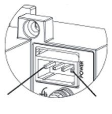
Type 8640
                                                                                                General information

Risk of burns/risk of fire if used continuously through hot device      4.     GENERAL INFORMATION
surface!
                                                                        4.1. Contact address
• Keep the device away from highly flammable substances and
  media and do not touch with bare hands.                               Germany
                                                                               Bürkert Fluid Control Systems
                                                                               Sales Center
        The Type 8640 AirLINE was developed with due consider-
                                                                               Christian-Bürkert-Str. 13-17
        ation given to accepted safety rules and is state-of-the-art.
                                                                               D-74653 Ingelfingen
        Nevertheless, dangerous situations may occur.
                                                                               Tel.  + 49 (0) 7940 - 10 91 111
                                                                               Fax  + 49 (0) 7940 - 10 91 448
NOTE!
                                                                               E-mail: info@de.buerkert.com
Electrostatic sensitive components/modules!
The device contains electronic components, which react sensitively      International
to electrostatic discharge (ESD). Contact with electrostatically
charged persons or objects is hazardous to these components. In         Contact addresses are found on the final pages of this operating
the worst case scenario, they will be destroyed immediately or will     manual.
fail after start-up.                                                    And also on the Internet under: www.burkert.com
• Observe the requirements in accordance with EN 61340-5-1
  and 5-2 to minimize/avoid the possibility of damage caused by a       4.2. Warranty
  sudden electrostatic discharge!                                       The warranty is only valid if the AirLINE Type 8640 is used as intended
• Also, ensure that you do not touch electronic components when         in accordance with the specified application conditions.
  the power supply voltage is present!
                                                                        4.3. Informations in the Internet
                                                                        The operating manual and the data sheets on Type 8640 can be found
                                                                        on the Internet under: www.burkert.com

6                               english
Type 8640
Technical data
5. TECHNICAL DATA 5.3.1. Rating plate
5.1. Conformity Type
The AirLINE system Type 8640 conforms with the EC Directives
Operating principle
according to the EC Declaration of Conformity.
Orifice
5.2. Standards
The applied standards, which verify conformity with the EC Direc-
MADE IN GERMANY
6525 H 4,0
tives, can be found on the EC-Type Examination Certificate and / or PN 2,5 - 7 bar
the EC Declaration of Conformity. 24 V DC 1W
5.3. General Technical Data 450000Y W14UN
Technical Data Pilot valve type 0460, Pilot valve type 0461, Identification number
6524, 6525 6526, 6527 Voltage (± 10 %), capacity
Pressure range Vac. up to 10 bar Vac. up to 10 bar
Pressure range
Operating 24 V DC 24 V DC
voltage Fig. 1: Location and description of the rating plate
Voltage tolerance ± 10 % ± 10 %
Ambient 0 ... +55 °C
temperature (when using Type 0460 and 0461: 0 ... +50 °C)
english 7Type 8640
Assembly
5.3.2. Fluid connection 6. ASSEMBLY
Type 6524 Type 6525 6.1. Safety instructions
DANGER!
Design the pressure supply
with the largest possible Risk of injury from high pressure in the equipment!
volume! • Before loosening lines or valves, turn off the pressure and vent
X* the lines.
X* 5/R
3/R 4/A Risk of injury due to electrical shock!
2/A 1/P
2/B • Before reaching into the device or the equipment, switch off the
1/P 3/S power supply and secure to prevent reactivation!
X* - pilot control
• Observe applicable accident prevention and safety regulations
Fig. 2: Fluid connection. Types 6524 and 6525 for electrical equipment!
5.3.3. Fluid and electrical connection
WARNING!
Observe pin
Type 6524 Risk of injury from improper assembly!
assignment!
(2 x 2/3-way valve)
• Installation may only be carried out by authorized technicians with
- Pin coil 12 12 Hand lever the appropriate tools!
14 assignment
controlled via bit “n+1” Risk of injury from unintentional activation of the system and
+ Pin X* - pilot control uncontrolled restart!
- Pin coil 14 X* • Secure system from unintentional activation.
controlled via bit “n” 5/R
4/A • Following assembly, ensure a controlled restart.
1/P Bit “n”
2/B
3/S
Bit “n+1”
Fig. 3: Fluid and electrical connection. Type 6524
8 englishType 8640
Assembly
CAUTION! 6.2. Assembly
DANGER!
Escape of medium and malfunction!
If the seals are not seated correctly, leaks and malfunctions may occur Danger of explosion!
due to pressure losses. If systems in the explosion-protected area are installed in a control
• Ensure that the seals are seated correctly in the area of the elec- cabinet, the following requirements must be met:
tronics and pneumatics. • The control cabinet must be authorized for use in the explosion-
Short-circuit, malfunction! protected area.
The electrical connection requires exact contacting. • The control cabinet must be large enough to allow the resulting lost
heat to be dissipated in a suitable manner to the outside.
• Do not bend contacts.
• The internal temperature of the control cabinet must not exceed
• If connections are damaged or bent, replace the affected the max. permitted ambient temperature for the device.
components.
Risk of electric shock!
• Do not switch on the system unless the components are in perfect
condition. • Before reaching into the device or the equipment, switch off the
power supply and secure to prevent reactivation!
NOTE!
6.2.1. Installation on standard rail
Operate the system with direct current only!
To prevent damage to the system, use only direct current for the
system power supply.
Prevent a pressure drop!
To prevent a pressure drop, design the system pressure supply with
the largest possible volume.
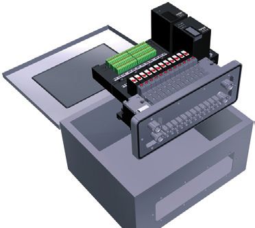
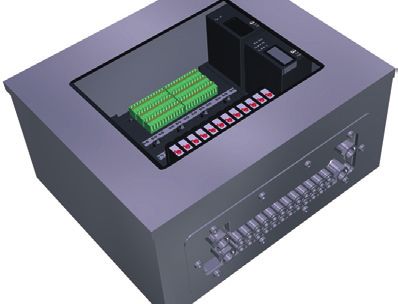
Fig. 4: Installation of a valve block into a control cabinet
english 9Type 8640
Assembly
→→Fasten the standard rail firmly in the control cabinet. →→Position the valve terminal in the control cabinet on the prepared
→→Establish a short, wide PE connection between the standard rail opening.
and the control cabinet. →→From outside attach the stability plate to prevent distortion and
The valve terminal must be freely accessible from above. secure with screws M 5 x 10 from the enclosed fastening set.
Ensure good heat dissipation!
Valve terminal
Recommended distance when installing in a control cabinet: Type 8640
A 30 mm C 30 mm
B 30 mm D 60 mm
AirLINE Quick
6.2.2. Installation of AirLINE Quick adapter
To install AirLINE Quick, a notch must be first of all provided on the
base or the wall of the control cabinet, e.g. through lasing or punching.
For the dimensions of the relevant flange image, refer to chapter
“6.2.3. Dimensions of the flange images for AirLINE Quick”. Control cabinet
The distances to the left, right, front and top depend on the selected Fig. 5: Placing the valve terminal in the control cabinet
valve terminal configuration.
Recommended distance in the control cabinet to the valve
terminal:
left right front top
30 mm 60 mm 30 mm 50 mm
NOTE!
Screws M 5 x 10
The opening on the control cabinet must be burr-free to
prevent damage to the seal of the AirLINE Quick adapter. Stability plate
→→Without damaging the seal of the AirLINE Quick adapter, insert it Fig. 6: Attaching the stability plate
into the groove of the flange opening.
10 englishType 8640
Assembly
6.2.3. Dimensions of the flange images for AirLINE Quick
Inside wall control cabinet
N4
N3
N2
t>=1.5 N1 Ø 5.3 ± 0.2
>=8
59 ± 0.3
73 ± 0.3
(96)
R 6.5
only at O= 6 and O = 10
M
G
Space requirements reinforcing frame outside
Fig. 7: Dimensions of the flange images for AirLINE Quick – for dimensions see “Tab. 1”, page 12
english 11Type 8640
Installation
Version 7. INSTALLATION
4-fold 8-fold 12-fold 16-fold 24-fold 7.1. Fluid Installation
Feature – – – – on request
DANGER!
M 111 ±0.4 155 ±0.4 199 ±0.4 243 ±0.4 331 ±0.4
N1 114 ±0.4 54 ±0.3 68 ±0.3 123 ±0.4 66 ±0.3 Risk of injury from high pressure in the equipment!
N2 – 158 ±0.4 202 ±0.4 246 ±0.4 200 ±0.4 • Before loosening lines or valves, turn off the pressure and vent
N3 – – – – 334 ±0.4 the lines.
N4 – – – – – • Design the connections with the largest possible volume.
O (Number of • Close the open connections not required with lock screws.
bores)
6 8 8 10 12
• The connections for the pilot control exhaust air (x) must not be
G 148 192 236 280 368 sealed.
Tab. 1: Dimensions of the flange images for AirLINE Quick. • Check correct assignment of the connections 1 and 3 or 5. They
may by no means be interchanged.
7.1.1. Pneumatic connections - feed
Exhaust air R/3, S/5
X channel:
Standard version:
Deaeration of the control valves
Control assist air version:
P connection for control valves
Pressure supply connection P/1
Fig. 8: Pneumatic connections
12 englishType 8640
Installation
Procedure: 7.1.3. neumatic connections -
P
→→Depending on the version, plug the connections in the corre- AirLINE standard
sponding working connections or screw them in.
NOTE!
For the plug-in connections the hose pipes must meet the following
requirements:
• Minimum hardness of 40 Shore D (in accordance with DIN Working connections
53505 or ISO 868); for 5/2-way and
• Outer diameter in accordance with DIN 73378 (max. permitted 2 x 3/2-way valves
deviation ± 0.1 mm of the nominal dimension);
Working connections
• Burr-free, cut off at right angles and undamaged on the outer for 3/2-way valves
diameter;
Fig. 9: Pneumatic connections - valve discs
The hose pipes must be pressed all the way into the plug-in
connections. Procedure:
→→Depending on the version, plug the connections in the corre-
sponding working connections (D6, D1/4) or screw them in (M7).
7.1.2. Removing the plug-in connections →→Connection nipples can be used for threaded versions.
→→To detach the pipes, press in the thrust ring and pull out the hose Inscription of the connections:
pipe.
→→Label the inscription areas with the data of the valve
connections.
english 13Type 8640
Installation
7.1.4. neumatic connections -
P 7.1.5. Fluid connection AirLINE Quick
AirLINE Quick
Example of
connection adapter
Air discharge connection R/S
Supply connection P
Fig. 11: Fluid connection AirLINE Quick
Procedure:
→→Screw connection adapter G1/4” or NPT 1/4” to connections P
and R/S.
Fig. 10: Pneumatic connections – AirLINE Quick
NOTE!
Procedure:
→→Depending on the version, plug the connections in the corre- Risk of leakage if screw connection is too tight!
sponding working connections. • When fitting the fluid connection adapters to the connections
P, R/S, observe the max. torque of 12 Nm. In doing so, counter
with a suitable tool to prevent the connections from turning!
14 englishType 8640
Installation
7.2. Fluid deinstallation 7.3. Electrical Installation
NOTE! DANGER!
Irreversible damage to the seal in the thread of the screw
Risk of injury due to electrical shock!
connection!
• Before reaching into the device or the equipment, switch off the
• When loosening the connection adapters, use a suitable tool to power supply and secure to prevent reactivation!
prevent the corresponding supply or air discharge connection
from turning. 7.3.1. onventional connection technology
C
(multipole and multiple connection)
Module Configuration
Multiple connection – Ground
Functional earth
Multi-pole connection Pin 1 Valve 1
for valve outputs
Pin 241) Valve 24
Pin 25 Ground
Multipole circuit Pin 1 Input 1
feedback indicator
inputs
Pin 32 Input 32
Pin 43 24 V
Pin 44 Ground
1) In manual/automatic mode Pin 24 is constantly supplied with 24 V.
english 15Type 8640
Installation
7.3.2. Field bus technology connections male IP20 Socket RJ45
Pin Profibus DP CanOpen / DeviceNet Profinet,
IP20 IP54 IP20 IP54 Ethernet/
IP, 12345678
Modbus D-SUB 9
TCP
1 n. c. +5 V n. c. Drain TX+
Pin 1 Pin 4
2 n. c. RxD/TxD-N/A- CAN LOW n. c. TX–
line
female
3 RxD/TxD-P/B- DGND GND GND RX+
line 7.3.3. Power supply connections
4 CNTR-P RxD/TxD-P/B- n. c. CAN HIGH n. c.
(RTS) line Pin All models
5 DGND Shield n. c. CAN LOW n. c. IP20 IP54
6 +5 V n. c. RX–
1 GND Outputs 24 V DC Outputs
7 n. c. CAN HIGH n. c.
8 RxD/TxD-N/A- n. c. n. c. 2 24 V DC Outputs 24 V DC Logic
line 3 GND Logic GND Logic
9 n. c. n. c. 4 24 V DC Logic GND Outputs
D-SUB 9 5-pole M12 D-SUB 9 5-pole RJ45
female female male Micro 12 female
(Reverse-Key)
16 englishType 8640
Installation
7.3.4. DIP switch settings 7.3.5. RIO - internal bus extension
Profibus-DP 24 V DC (2)
Outputs
1 2 3 4 5 6 7 8 24 V DC (4)
Logic
Address of the profibus DP subscriber - 125 OFF
Electronics Inputs Outputs
DeviceNet / CanOpen GND (3)
Logik
1 2 3 4 5 6 7 8
GND (1)
Address of the field bus module 0 – 63 Baud rate Outputs
Fig. 12: Power supply
Baud rate
DIP 7/8 DVN COP
0 125 kB 20 kB
1 250 kB 125 kB
2 500 kB 250 kB
3 - 500 kB
4 2 CAN LOW
Internal field bus: 4-pole socket M8 3 1 CAN HIGH
Field bus settings:
DIP switches
1 2 3 4 5 6 7 8
Address on the in- Mode inputs Reserve Terminating
ternal RIO bus always OFF resistors
english 17Type 8640
Installation
7.3.6. ddress on the internal RIO bus:
A 7.3.7. Mode inputs: DIP switches 4 and 5
DIP switches 1 to 3 NOTE!
Each peripheral terminal has a unique address. This address is set
The input modes allow the entries (feedback indicator) to be
on the valve terminal via DIP switches 1 to 3.
assigned in different ways in the process image of the inputs
DIP 1 DIP 2 DIP 3 Address Peripheral (PAE).
terminal
DIP 4 DIP 5
OFF OFF OFF 0 0
ON OFF OFF 1 1 No entries available OFF OFF
OFF ON OFF 2 2 Normal mode ON OFF
ON ON OFF 3 3 Mode: shifted inputs OFF ON
OFF OFF ON 4 4 Mode: halved inputs ON ON
ON OFF ON 5 5
OFF ON ON 6 6 CAUTION!
ON ON ON 7 7
If there are no inputs available, both switches must be set to OFF.
18 englishType 8640
Start-Up
8. START-UP 10. TRANSPORT, STORAGE, DISPOSAL
WARNING! NOTE!
Risk of injury from improper operation! Transport damages!
Improper operation may result in injuries as well as damage to the Inadequately protected equipment may be damaged during transport.
device and the area around it. • During transportation protect the device against wet and dirt in
• Before start-up, ensure that the operating personnel are familiar shock-resistant packaging.
with and completely understand the contents of the operating • Avoid exceeding or dropping below the permitted storage
instructions. temperature.
• Observe the safety instructions and intended use.
• Only adequately trained personnel may start up the equipment/ Incorrect storage may damage the device!
the device. • Store the device in a dry and dust-free location!
NOTE! • Storage temperature: -20 ... +60 °C.
• Switch on the supply pressure. Damage to the environment caused by device components
• Only then switch on the power supply! contaminated with media!
• Ensure the device and packaging are disposed of in an environ-
Procedures before fluid start-up: mentally sound manner.
→→Check connections, voltage and operating pressure. • Observe applicable regulations relating to refuse disposal and
→→Ensure that max. operating data are not exceeded. the environment.
→→Check correct assignment of the connections 1 and 3 or 5. They • Observe the national waste disposal regulations.
may by no means be interchanged.
→→Release manual actuation during electrical operation.
9. MAINTENANCE
See “7.2. Fluid deinstallation”, page 15.
english 19Typ 8640
Inhaltsverzeichnis
1. DER QUICKSTART........................................................................................ 21 6. MONTAGE......................................................................................................... 25
1.1. Begriffsdefinition Gerät..................................................................21 6.1. Sicherheitshinweise........................................................................25
1.2. Darstellungsmittel............................................................................21 6.2. Montage............................................................................................26
2. BESTIMMUNGSGEMÄSSE VERWENDUNG2����������������������������������� 22 7. INSTALLATION................................................................................................ 29
2.1. Beschränkungen.............................................................................22 7.1. Fluidische Installation.....................................................................29
7.2. Fluidische Deinstallation................................................................32
3. GRUNDLEGENDE SICHERHEITSHINWEISE.................................. 22
7.3. Elektrische Installation....................................................................32
4. ALLGEMEINE HINWEISE........................................................................... 23 8. INBETRIEBNAHME....................................................................................... 36
4.1. Kontaktadresse................................................................................23
4.2. Gewährleistung...............................................................................23 9. WARTUNG......................................................................................................... 36
4.3. Informationen im Internet...............................................................23
10. TRANSPORT, LAGERUNG, VERPACKUNG................................... 36
5. TECHNISCHE DATEN................................................................................. 24
5.1. Konformität........................................................................................24
5.2. Normen..............................................................................................24
5.3. Allgemeine technische Daten.......................................................24
20 deutschTyp 8640
Der Quickstart
1. DER QUICKSTART 1.2. Darstellungsmittel
Der Quickstart beschreibt den gesamten Lebenszyklus des Geräts. In dieser Anleitung werden folgende Darstellungsmittel verwendet.
Bewahren Sie diese Anleitung so auf, dass sie für jeden Benutzer gut
GEFAHR!
zugänglich ist und jedem neuen Eigentümer des Geräts wieder zur
Verfügung steht. Warnt vor einer unmittelbaren Gefahr!
• Bei Nichtbeachtung sind Tod oder schwere Verletzungen die
Wichtige Informationen zur Sicherheit! Folge.
Lesen Sie den Quickstart sorgfältig durch. Beachten Sie vor allem
die Kapitel „Grundlegende Sicherheitshinweise“ und „Bestimmungs- WARNUNG!
gemäße Verwendung“. Warnt vor einer möglicherweise gefährlichen Situation!
• Der Quickstart muss gelesen und verstanden werden. • Bei Nichtbeachtung können schwere Verletzungen oder Tod die
Folge sein.
Der Quickstart erläutert beispielhaft die Montage und Inbetriebnahme VORSICHT!
des Geräts. Die ausführliche Beschreibung des Geräts finden Sie in
der Bedienungsanleitung für den Typ 8640. Warnt vor einer möglichen Gefährdung!
• Nichtbeachtung kann mittelschwere oder leichte Verletzungen
Die Bedienungsanleitung finden Sie auf der beigelegten CD zur Folge haben.
oder im Internet unter: www.buerkert.de
HINWEIS!
1.1. Begriffsdefinition Gerät
Warnt vor Sachschäden!
Der in dieser Anleitung verwendeten Begriff „Gerät“ steht immer für
das System AirLINE Typ 8640.
Wichtige Tipps und Empfehlungen.
Verweist auf Informationen in dieser Bedienungsanleitung
oder in anderen Dokumentationen.
→→markiert einen Arbeitsschritt den Sie ausführen müssen.
deutsch 21Typ 8640
Bestimmungsgemäße Verwendung
2. BESTIMMUNGSGEMÄSSE 3. GRUNDLEGENDE
VERWENDUNG SICHERHEITSHINWEISE
Bei nicht bestimmungsgemäßem Einsatz der AirLINE Typ 8640 Diese Sicherheitshinweise berücksichtigen keine
können Gefahren für Personen, Anlagen in der Umgebung und • Zufälligkeiten und Ereignisse, die bei Montage, Betrieb und Wartung
die Umwelt entstehen. der Geräte auftreten können.
• Das Gerät darf zur Steuerung pneumatisch betriebener Geräte • ortsbezogenen Sicherheitsbestimmungen, für deren Einhaltung, auch
eingesetzt werden. in Bezug auf das Montagepersonal, der Betreiber verantwortlich ist.
• Das Gerät nicht ungeschützt im Außenbereich einsetzen.
• Das Gehäuse nicht mechanisch belasten (z. B. durch Ablage von
Gegenständen oder als Trittstufe). Allgemeine Gefahrensituationen.
• Für den Einsatz die in den Vertragsdokumenten und der Bedie- Zum Schutz vor Verletzungen ist zu beachten:
nungsanleitung spezifizierten zulässigen Daten, Betriebs- und
Einsatzbedingungen beachten. Diese sind im Kapitel „Techni- • Dass die Anlage nicht unbeabsichtigt betätigt werden kann.
sche Daten“ beschrieben. • In Systemen, die unter Druck stehen, dürfen Leitungen und Ventile
• Das Gerät nur in Verbindung mit von Bürkert empfohlenen bzw. nicht gelöst werden.
zugelassenen Fremdgeräten und -komponenten einsetzen. • Vor Eingriffen in das System in jedem Fall die Spannung abschalten.
• Voraussetzungen für den sicheren und einwandfreien Betrieb sind • Druckversorgung möglichst großvolumig ausführen, um Druckabfall
sachgemäßer Transport, sachgemäße Lagerung und Installation beim Schalten zu vermeiden.
sowie sorgfältige Bedienung und Instandhaltung. • Installations- und Instandhaltungsarbeiten dürfen nur von auto-
• In die Medienanschlüsse des Systems keine aggressiven oder risiertem Fachpersonal mit geeignetem Werkzeug ausgeführt
brennbaren Medien einspeisen. werden.
• Setzen Sie das Gerät nur bestimmungsgemäß ein. • Das Gerät darf nur in einwandfreiem Zustand und unter Beachtung
der Bedienungsanleitung betrieben werden.
• Nach einer Unterbrechung der elektrischen oder pneumatischen
2.1. Beschränkungen Versorgung ist ein definierter oder kontrollierter Wiederanlauf des
Beachten Sie bei der Ausfuhr des Systems/Geräts gegebenenfalls Prozesses zu gewährleisten.
bestehende Beschränkungen. • Für die Einsatzplanung und den Betrieb des Geräts müssen die
allgemeinen Regeln der Technik eingehalten werden.
22 deutschTyp 8640
Allgemeine Hinweise
Verbrennungsgefahr/Brandgefahr bei Dauerbetrieb durch 4. ALLGEMEINE HINWEISE
heiße Geräteoberfläche!
4.1. Kontaktadresse
• Das Gerät von leicht brennbaren Stoffen und Medien fernhalten
und nicht mit bloßen Händen berühren. Deutschland
Bürkert Fluid Control Systems
Sales Center
Der Typ 8640 AirLINE wurde unter Einbeziehung der aner- Christian-Bürkert-Str. 13-17
kannten sicherheitstechnischen Regeln entwickelt und ent- D-74653 Ingelfingen
spricht dem Stand der Technik. Trotzdem können Gefahren Tel. + 49 (0) 7940 - 10 91 111
entstehen. Fax + 49 (0) 7940 - 10 91 448
E-mail: info@de.buerkert.com
HINWEIS!
Elektrostatisch gefährdete Bauelemente / Baugruppen! International
Das Gerät enthält elektronische Bauelemente, die gegen elektrosta- Die Kontaktadressen finden Sie auf den letzten Seiten der
tische Entladung (ESD) empfindlich reagieren. Berührung mit elek- gedruckten Bedienungsanleitung.
trostatisch aufgeladenen Personen oder Gegenständen gefährdet
Außerdem im Internet unter: www.burkert.com
diese Bauelemente. Im schlimmsten Fall werden sie sofort zerstört
oder fallen nach der Inbetriebnahme aus.
• Beachten Sie die Anforderungen nach EN 61340-5-1 und 5-2,
4.2. Gewährleistung
um die Möglichkeit eines Schadens durch schlagartige elektro- Voraussetzung für die Gewährleistung ist der bestimmungsgemäße
statische Entladung zu minimieren bzw. zu vermeiden! Gebrauch der AirLINE Typ 8640 unter Beachtung der spezifizierten
Einsatzbedingungen.
• Achten Sie ebenso darauf, dass Sie elektronische Bauelemente
nicht bei anliegender Versorgungsspannung berühren!
4.3. Informationen im Internet
Bedienungsanleitungen und Datenblätter zum Typ 8640 finden Sie im
Internet unter: www.buerkert.de
deutsch 23Typ 8640
Technische Daten
5. TECHNISCHE DATEN 5.3.1. Typenschild
5.1. Konformität Typ
Das AirLINE System Typ 8640 ist konform zu den EG-Richtlinien
Wirkungsweise
entsprechend der Konformitätserklärung.
Nennweite
5.2. Normen
Die angewandten Normen, mit denen die Konformität mit den EG-
MADE IN GERMANY
6525 H 4,0
Richtlinien nachgewiesen wird, sind in der Baumusterprüfbeschei- PN 2,5 - 7 bar
nigung und/oder der EG-Konformitätserklärung nachzulesen. 24 V DC 1W
450000Y W14UN
5.3. Allgemeine technische Daten Identnummer
Technische Pilotventil Typ 0460, Pilotventil Typ 0461, Spannung (± 10 %), Leistung
Daten 6524, 6525 6526, 6527
Druckbereich
Druckbereich Vak. bis 10 bar Vak. bis 10 bar
Bild 1: Lage und Beschreibung des Typenschildes
Betriebs- 24 V DC 24 V DC
spannung
Spannungs- ± 10 % ± 10 %
toleranz
Umgebungs- 0 ... +55 °C
temperatur (bei Verwendung des Typs 0460 und 0461:
0 ... +50 °C)
24 deutschTyp 8640
Montage
5.3.2. Fluidischer Anschluss 6. MONTAGE
Typ 6524 Typ 6525 6.1. Sicherheitshinweise
GEFAHR!
Druckversorgung möglichst
großvolumig ausführen! Verletzungsgefahr durch hohen Druck in der Anlage!
• Vor dem Lösen von Leitungen oder Ventilen den Druck abschal-
X*
5/R ten und Leitungen entlüften.
X*
3/R 4/A Verletzungsgefahr durch Stromschlag!
2/A 1/P
2/B • Vor Eingriffen in das Gerät oder die Anlage, Spannung abschal-
1/P 3/S ten und vor Wiedereinschalten sichern!
X* - Vorsteuerabluft
• Die geltenden Unfallverhütungs- und Sicherheitsbestimmungen
Bild 2: Fluidischer Anschluss. Typen 6524 und 6525 für elektrische Geräte beachten!
5.3.3. luidischer und elektrischer
F WARNUNG!
Anschluss
Typ 6524 Pinbelegung Verletzungsgefahr bei unsachgemäßer Montage!
(2 x 2/3-Wege Ventil) beachten! • Die Montage darf nur autorisiertes Fachpersonal mit geeignetem
Werkzeug durchführen!
– Pol Spule 12 12 Handhebel-
angesteuert über Bit „n+1“ 14 zuordnung Verletzungsgefahr durch ungewolltes Einschalten der Anlage
+ Pol und unkontrollierten Wiederanlauf!
X* X* - Vorsteuerabluft • Anlage vor unbeabsichtigtem Betätigen sichern.
– Pol Spule 14
angesteuert über Bit „n“ 5/R • Nach der Montage einen kontrollierten Wiederanlauf
4/A gewährleisten.
1/P Bit „n“
2/B
3/S
Bit „n+1“
Bild 3: Fluidischer und elektrischer Anschluss. Typ 6524
deutsch 25Typ 8640
Montage
VORSICHT! 6.2. Montage
Mediumsaustritt und Fehlfunktion! GEFAHR!
Bei mangelhaftem Sitz der Dichtungen können Undichtigkeiten und Explosionsgefahr!
Funktionsbeeinträchtigungen durch Druckverluste auftreten. Bei Systemen im explosionsgeschützten Bereich, die in einem
• Auf korrekten Sitz der Dichtungen im Bereich der Elektronik und Schaltschrank eingesetzt sind, muss folgendes sichergestellt sein:
Pneumatik achten.
• Der Schaltschrank muss für den Einsatz im explosionsgeschütz-
Kurzschluss, Funktionsausfall! ten Bereich zugelassen sein.
Der elektrische Anschluss erfordert exakte Kontaktierung. • Der Schaltschrank muss so groß dimensioniert werden, dass
• Kontakte nicht verbiegen. die entstehende Verlustwärme in geeigneter Weise nach außen
abgeführt werden kann.
• Bei beschädigten oder verbogenen Anschlüssen die betroffenen
Komponenten austauschen. • Die Innentemperatur des Schaltschranks darf die max. zulässige
Umgebungstemperatur für das Gerät nicht überschreiten.
• Das System nur bei einwandfreiem Zustand der Komponenten
einschalten. Gefahr durch elektrische Spannung!
• Vor Eingriffen in das Gerät oder die Anlage Spannung abschal-
HINWEIS! ten und vor Wiedereinschalten sichern!
System nur mit Gleichstrom betreiben! 6.2.1. Montage auf der Normschiene
Um Schäden am System zu vermeiden für die Stromversorgung
des Systems ausschließlich Gleichstrom einsetzen.
Druckabfall vermeiden!
Um einen Druckabfall zu vermeiden, die Druckversorgung des
Systems möglichst großvolumig ausführen.
Bild 4: Einbau des Ventilblocks in einen Schaltschrank
26 deutschTyp 8640
Montage
→→Die Normschiene fest im Schaltschrank montieren. →→Die Ventilinsel im Schaltschrank auf den vorbereiteten Ausbruch
→→Eine kurze, breite PE-Verbindung zwischen Normschiene und platzieren.
Schaltschrank herstellen. →→Von außen das Stabilisierungsblech zur Vermeidung von Verwer-
fungen anbringen und mit Schrauben M 5 x 10 des beiliegenden
Die Ventilinsel muss nach oben frei zugänglich sein.
Befestigungssatzes befestigen.
Für gute Wärmeabfuhr sorgen!
Abstandsempfehlung beim Einbau in den Schaltschrank: Ventilinsel
Typ 8640
A 30 mm C 30 mm
B 30 mm D 60 mm
6.2.2. Montage AirLINE Quick AirLINE Quick
Zur Montage von AirLINE Quick muss zuerst ein Ausbruch am Schalt- Adapter
schrankboden bzw. der Schaltschrankwand vorgesehen werden. Dies
kann z. B. durch Lasern oder Stanzen erfolgen.
Die Abmessungen des entsprechenden Flanschbildes siehe Kapitel
„6.2.3. Abmessungen der Flanschbilder für AirLINE Quick“. Schaltschrank
Die Abstände nach links, rechts, vorne und oben sind abhängig von Bild 5: Platzieren der Ventilinsel im Schaltschrank
der gewählten Ventilinselkonfiguration.
Empfehlung Abstand im Schaltschrank zur Ventilinsel:
links rechts vorne oben
30 mm 60 mm 30 mm 50 mm
HINWEIS!
Der Ausbruch am Schaltschrank muss gratfrei sein, damit die Schrauben M 5 x 10
Dichtung des AirLINE Quick Adapters nicht beschädigt wird.
Stabilisierungsblech
→→Dichtung des AirLINE Quick Adapters beschädigungsfrei in die Bild 6: Befestigung des Stabilisierungsblechs
Nut der Flanschöffnung einlegen
deutsch 27Typ 8640
Montage
6.2.3. Abmessungen der Flanschbilder für AirLINE Quick
Schaltschrank-Innenwand
N4
N3
N2
t>=1,5 N1 Ø 5,3 ± 0,2
>=8
59 ± 0,3
73 ± 0,3
(96)
R 6,5
nur bei O= 6 und O = 10
M
G
Platzbedarf Versteifungsrahmen Außenseite
Bild 7: Flanschbilder AirLINE Quick – Maße siehe Tab. 1 auf Seite 29
28 deutschTyp 8640
Installation
Ausführung 7. INSTALLATION
4-fach 8-fach 12-fach 16-fach 24-fach 7.1. Fluidische Installation
Besonderheit – – – – auf Anfrage
GEFAHR!
M 111 ±0,4 155 ±0,4 199 ±0,4 243 ±0,4 331 ±0,4
N1 114 ±0,4 54 ±0,3 68 ±0,3 123 ±0,4 66 ±0,3 Verletzungsgefahr durch hohen Druck in der Anlage!
N2 – 158 ±0,4 202 ±0,4 246 ±0,4 200 ±0,4 • Vor dem Lösen von Leitungen oder Ventilen den Druck abschalten
N3 – – – – 334 ±0,4 und Leitungen entlüften.
N4 – – – – – • Die Anschlüsse möglichst großvolumig ausführen.
O (Anzahl • Nicht benötigte, offene Anschlüsse mit Verschlussschrauben
Bohrungen)
6 8 8 10 12 schließen.
G 148 192 236 280 368 • Die Anschlüsse für die Vorsteuerabluft (x) dürfen nicht verschlos-
Tab. 1: Abmessungen Flanschbilder AirLINE Quick sen werden.
• Die vorschriftsmäßige Belegung der Anschlüsse 1 und 3 bzw. 5
überprüfen. Diese dürfen auf keinen Fall vertauscht werden.
7.1.1. Pneumatische Anschlüsse –
Einspeisung
Abluft R/3, S/5
X-Kanal
Standardausführung:
Entlüftung der Steuerventile
Steuerhilfsluftausführung:
P-Anschluss für Steuerventile
Druckversorgungsanschluss P/1
Bild 8: Pneumatische Anschlüsse
deutsch 29Typ 8640
Installation
Vorgehensweise: 7.1.3. neumatische Anschlüsse –
P
→→Die Anschlüsse je nach Ausführung an den entsprechenden AirLINE Standard
Arbeitsanschlüssen einstecken oder einschrauben.
HINWEIS!
Für die Steckanschlüsse müssen die Schlauchleitungen folgende
Anforderungen erfüllen:
• Mindesthärte von 40 Shore D (nach DIN 53505 bzw. ISO 868); Arbeitsanschlüsse bei
• Außendurchmesser entsprechend DIN 73378 (max. zulässige 5/2-Wege- und
Abweichung ± 0,1 mm vom Nennmaß); 2 x 3/2-Wege-Ventilen
• Gratfrei, rechtwinklig abgeschnitten und am Außendurchmesser Arbeitsanschlüsse bei
unbeschädigt; 3/2-Wege-Ventilen
Die Schlauchleitungen sind bis zum Anschlag in die Steckanschlüsse
einzudrücken. Bild 9: Pneumatische Anschlüsse - Ventilscheiben
Vorgehensweise:
→→Die Anschlüsse je nach Ausführung an den entsprechenden
7.1.2. Demontage der Steckanschlüsse Arbeitsanschlüssen einstecken oder einschrauben.
→→Zum Lösen der Leitungen den Druckring eindrücken und die →→Bei Gewindeausführung können Anschlussnippel verwendet
Schlauchleitung herausziehen. werden.
Beschriftung der Anschlüsse:
→→Die Beschriftungsfelder mit den Daten der Ventilanschlüsse
beschriften.
30 deutschTyp 8640
Installation
7.1.4. neumatische Anschlüsse –
P 7.1.5. Fluidischer Anschluss AirLINE Quick
AirLINE Quick
Beispiel für
Anschlussadapter
Entlüftungsanschluss R/S
Versorgungsanschluss P
Bild 11: Fluidischer Anschluss AirLINE Quick
Vorgehensweise:
→→Anschlussadapter G1/4“ bzw. NPT 1/4“ an Anschlüsse P und
R/S schrauben.
Bild 10: Pneumatische Anschlüsse – AirLINE Quick
HINWEIS!
Vorgehensweise:
→→Die Anschlüsse an den entsprechenden Arbeitsanschlüssen Gefahr der Leckage bei zu starker Verschraubung!
einstecken. • Bei Montage der fluidischen Anschlussadapter an die
Anschlüsse P, R/S das max. Drehmoment von 12 Nm beachten.
Hierbei durch Gegenhalten mit einem geeigneten Werkzeug
das Verdrehen der Anschlüsse verhindern!
deutsch 31Typ 8640
Installation
7.2. Fluidische Deinstallation 7.3. Elektrische Installation
HINWEIS! GEFAHR!
Irreversible Beschädigung der Dichtung im Gewinde der
Verletzungsgefahr durch Stromschlag!
Verschraubung!
• Vor Eingriffen in das Gerät oder die Anlage Spannung abschalten
• Beim Lösen der Anschlussadapter das Verdrehen des ent- und vor Wiedereinschalten sichern!
sprechenden Versorgungs- oder Entlüftungsanschlusses mit
geeignetem Werkzeug verhindern.
7.3.1. onventionelle Anschlusstechnik
K
(Multipol und Sammelanschluss)
Modul Belegung
Sammelanschluss – Ground
Funktionserde
Multipolanschaltung Pin 1 Ventil 1
Ventilausgänge
Pin 241) Ventil 24
Pin 25 Ground
Multipolanschaltung Pin 1 Eingang 1
mit Rückmelder-
eingängen
Pin 32 Eingang 32
Pin 43 24 V
Pin 44 Ground
1) Bei Handautomatik ist Pin 24 konstant mit 24 V belegt.
32 deutschTyp 8640
Installation
7.3.2. Anschlüsse Feldbustechnik male IP20 Buchse RJ45
Pin Profibus DP CanOpen / DeviceNet Profinet,
IP20 IP54 IP20 IP54 Ethernet/
IP, 12345678
Modbus D-SUB 9
TCP
1 n. c. +5 V n. c. Drain TX+
Pin 1 Pin 4
2 n. c. RxD/TxD-N/A- CAN LOW n. c. TX–
Leitung
female
3 RxD/TxD-P/B- DGND GND GND RX+
Leitung 7.3.3. Anschlüsse Spannungsversorgung
4 CNTR-P RxD/TxD-P/B- n. c. CAN HIGH n. c.
(RTS) Leitung Pin Alle Ausführungen
5 DGND Schirm n. c. CAN LOW n. c. IP20 IP54
6 +5 V n. c. RX– 1 GND Outputs 24 V DC Outputs
7 n. c. CAN HIGH n. c.
2 24 V DC Outputs 24 V DC Logik
8 RxD/TxD-N/A- n. c. n. c.
Leitung 3 GND Logik GND Logik
9 n. c. n. c. 4 24 V DC Logik GND Outputs
D-SUB 9 5-polig M12 D-SUB 9 5-polig RJ45
female female male Micro 12 female
(Reverse-Key)
deutsch 33Typ 8640
Installation
7.3.4. DIP-Schalter Einstellungen 7.3.5. Busmodul RIO-Slave
Profibus-DP 24 V DC (2)
Ausgänge
1 2 3 4 5 6 7 8 24 V DC (4)
Logik
Adresse des Profibus DP - Teilnehmers - 125 OFF
Elektronik Eingänge Ausgänge
DeviceNet / CanOpen GND (3)
Logik
1 2 3 4 5 6 7 8
GND (1)
Adresse des Feldbusmoduls 0 ... 63 Baudrate Ausgänge
Bild 12: Spannungsversorgung
Baudrate
DIP 7/8 DVN COP
0 125 kB 20 kB
1 250 kB 125 kB
2 500 kB 250 kB
3 - 500 kB
4 2 CAN LOW
Interner Feldbus: 4-polige Buchse M8 3 1 CAN HIGH
Feldbus Einstellungen:
DIP-Schalter
1 2 3 4 5 6 7 8
Adresse am Modus Reserve Abschlusswider-
internen RIO-Bus Eingänge immer OFF stände
34 deutschTyp 8640
Installation
7.3.6. dresse am internen RIO-Bus:
A 7.3.7. odus Eingänge:
M
DIP-Schalter 1 bis 3 DIP-Schalter 4 und 5
Jede Erweiterungsinsel hat eine eindeutige Adresse. An der Ventil- HINWEIS!
insel wird diese Adresse über die DIP-Schalter 1 bis 3 eingestellt. Mit den Eingangs-Modi können die Einträge (Rückmelder) im
DIP 1 DIP 2 DIP 3 Adresse Erweite- Prozessabbild der Eingänge (PAE) unterschiedlich zugeordnet
rungsinsel werden.
OFF OFF OFF 0 0 DIP 4 DIP 5
ON OFF OFF 1 1
Keine Einträge OFF OFF
OFF ON OFF 2 2 vorhanden
ON ON OFF 3 3
Normaler Modus ON OFF
OFF OFF ON 4 4
ON OFF ON 5 5 Modus: Versetzte OFF ON
Eingänge
OFF ON ON 6 6
ON ON ON 7 7 Modus: Halbierte ON ON
Eingänge
VORSICHT!
Sind keine Eingänge vorhanden, so sind die beiden Schalter auf
OFF zu stellen.
deutsch 35Typ 8640
Inbetriebnahme
8. INBETRIEBNAHME 10. TRANSPORT, LAGERUNG,
WARNUNG! VERPACKUNG
HINWEIS!
Verletzungsgefahr bei unsachgemäßem Betrieb!
Transportschäden!
Nicht sachgemäßer Betrieb kann zu Verletzungen, sowie Schäden
am Gerät und seiner Umgebung führen. Unzureichend geschützte Geräte können durch den Transport
• Vor der Inbetriebnahme muss gewährleistet sein, dass der Inhalt beschädigt werden.
der Bedienungsanleitung dem Bedienungspersonal bekannt ist • Gerät vor Nässe und Schmutz geschützt in einer stoßfesten
und vollständig verstanden wurde. Verpackung transportieren.
• Die Sicherheitshinweise und die bestimmungsgemäße Verwen- • Eine Über- bzw. Unterschreitung der zulässigen Lagertempe-
dung müssen beachtet werden. ratur vermeiden.
• Nur ausreichend geschultes Personal darf die Anlage/das Gerät
in Betrieb nehmen.
Falsche Lagerung kann Schäden am Gerät verursachen.
HINWEIS! • Gerät trocken und staubfrei lagern!
• Schalten Sie den Versorgungsdruck ein. • Lagertemperatur: –20 ... +60 °C.
• Schalten Sie erst danach die Spannung ein!
Maßnahmen vor der fluidischen Inbetriebnahme: Umweltschäden durch von Medien kontaminierte Geräteteile.
→→Anschlüsse, Spannung und Betriebsdruck überprüfen. • Gerät und Verpackung umweltgerecht entsorgen!
→→Beachten, dass max. Betriebsdaten nicht überschritten werden. • Geltende Entsorgungsvorschriften und Umweltbestimmungen
→→Die vorschriftsmäßige Belegung der Anschlüsse 1 und 3 bzw. 5 einhalten.
überprüfen. Diese dürfen auf keinen Fall vertauscht werden. • Die nationalen Abfallbeseitigungsvorschriften beachten.
→→Bei elektrischem Betrieb die Handbetätigung entriegeln.
9. WARTUNG
Siehe „7.2. Fluidische Deinstallation“ auf Seite 32.
36 deutschType 8640
Sommaire
1. QUICKSTART................................................................................................... 38 6. MONTAGE......................................................................................................... 42
1.1. Définition du terme appareil..........................................................38 6.1. Consignes de sécurité...................................................................42
1.2. Symboles..........................................................................................38 6.2. Montage............................................................................................43
2. UTILISATION CONFORME....................................................................... 39 7. INSTALLATION................................................................................................ 46
2.1. Restrictions.......................................................................................39 7.1. Installation fluidique........................................................................46
7.2. Désinstallation fluidique.................................................................49
3. CONSIGNES DE SÉCURITÉ GÉNÉRALES...................................... 39 7.3. Installation électrique......................................................................49
4. INDICATIONS GÉNÉRALES..................................................................... 40 8. MISE EN SERVICE........................................................................................ 53
4.1. Adresse.............................................................................................40
4.2. Garantie légale.................................................................................40 9. ENTRETIEN....................................................................................................... 53
4.3. Information sur Internet..................................................................40
10. TRANSPORT, STOCKAGE, ÉLIMINATION...................................... 53
5. CARACTÉRISTIQUES TECHNIQUES................................................. 41
5.1. Conformité........................................................................................41
5.2. Normes..............................................................................................41
5.3. Caractéristiques techniques générales.....................................41
français 37Type 8640
Quickstart
1. QUICKSTART 1.2. Symboles
Quickstart décrit le cycle de vie complet de l’appareil. Conservez-le Les moyens de représentation suivants sont utilisés dans les présentes
de sorte qu’il soit accessible à tout utilisateur et à disposition de tout instructions de service.
nouveau propriétaire.
DANGER !
Informations importantes pour la sécurité ! Met en garde contre un danger imminent !
Lisez attentivement Quickstart. Tenez compte en particulier des cha- • Le non-respect peut entraîner la mort ou de graves blessures.
pitres « Consignes de sécurité générales » et « Utilisation conforme ».
AVERTISSEMENT !
• Les instructions de service Quickstart doivent être lues et
comprises. Met en garde contre une situation éventuellement dangereuse !
• Risque de blessures graves, voire la mort en cas de non-respect.
Quickstart explique par des exemples le montage et la mise en service
de l’appareil. ATTENTION !
Vous trouverez la description détaillée de l’appareil dans le manuel Met en garde contre un risque possible !
d’utilisation du type 8640. • Le non-respect peut entraîner des blessures légères ou de
moyenne gravité.
Vous trouverez les instructions de service sur le cédérom joint
ou sur internet sous : REMARQUE !
www.buerkert.fr
Met en garde contre des dommages matériels !
1.1. Définition du terme appareil
Le terme « appareil » utilisé dans ces instructions désigne toujours le Conseils et recommandations importants.
système AirLINE type 8640.
Renvoie à des informations dans ces instructions de service
ou dans d’autres documentations.
→→identifie une opération que vous devez effectuer.
38 françaisType 8640
Utilisation conforme
2. UTILISATION CONFORME 3. CONSIGNES DE SÉCURITÉ
L’utilisation non conforme de l’AirLINE du type 8640 peut pré- GÉNÉRALES
senter des dangers pour les personnes, les installations proches Les présentes consignes de sécurité ne tiennent pas compte :
et l’environnement. • Des circonstances fortuites et des événements qui peuvent survenir
• L’appareil peut être utilisé pour commander des appareils à lors du montage, du fonctionnement et de la maintenance.
entraînement pneumatique.
• Des prescriptions de sécurité applicables au niveau local, dont le
• N’utilisez pas l’appareil à l’extérieur sans protection. respect relève de la responsabilité de l’exploitant, y compris pour le
• Lors de l’utilisation, il convient de respecter les données et condi- personnel de montage.
tions d’utilisation et d’exploitation admissibles spécifiées dans
les instructions de service et dans les documents contractuels. Situations dangereuses d’ordre général.
Celles-ci sont décrites au chapitre « Caractéristiques techniques ». Pour prévenir les blessures, respectez ce qui suit :
• L’appareil peut être utilisé uniquement en association avec les • L’installation ne peut pas être actionnée par inadvertance.
appareils et composants étrangers recommandés et homologués
par Bürkert. • Notez que, dans les systèmes sous pression, il est interdit de
• Les conditions pour l’utilisation sûre et parfaite sont un transport, desserrer les conduites et les vannes.
un stockage et une installation dans les règles ainsi qu’une parfaite • Avant d’intervenir dans le système, coupez en tous les cas la
utilisation et maintenance. tension.
• Ne pas alimenter les raccords du système en fluides agressifs • Dimensionnez la pression d’alimentation le plus généreusement
ou inflammables. possible, afin d’éviter les chutes de pression lors de la commutation.
• Ne pas soumettre le corps à des contraintes mécaniques (par ex. • Les travaux d’installation et de maintenance doivent être effectués
pour déposer des objets ou en l’utilisant comme marche). uniquement par des techniciens qualifiés et habilités disposant de
• Veillez à ce que l’utilisation de l’appareil soit toujours conforme. l’outillage approprié.
• Après une interruption de l’alimentation électrique ou pneumatique,
un redémarrage défini ou contrôlé du processus doit être garanti.
2.1. Restrictions • L’appareil doit être utilisé uniquement en parfait état et en respec-
Lors de l’exportation du système / de l’appareil, veuillez respecter les tant les instructions de service.
restrictions éventuelles existantes. • Les règles générales de la technique sont d’application pour
planifier l’utilisation et utiliser l’appareil.
français 39Type 8640
Indications générales
Risque de brûlures/d’incendie en fonctionnement continu dû 4. INDICATIONS GÉNÉRALES
à des surfaces d’appareils brûlantes !
4.1. Adresse
• Tenez les substances et les fluides facilement inflammables à l’écart
de l’appareil et ne touchez pas ce dernier à mains nues. Allemagne
Bürkert Fluid Control Systems
Sales Center
L’AirLINE du type 8640 a été développé dans le respect des
Christian-Bürkert-Str. 13-17
règles reconnues en matière de sécurité et correspond à l’état
D-74653 Ingelfingen
actuel de la technique. Néanmoins, des risques peuvent se
Tel. + 49 (0) 7940 - 10 91 111
présenter.
Fax + 49 (0) 7940 - 10 91 448
REMARQUE ! E-mail: info@de.buerkert.com
Eléments/sous-groupes sujets aux risques électrostatiques !
International
L’appareil contient des éléments électroniques sensibles aux
décharges électrostatiques (ESD). Ces éléments sont affectés Les adresses se trouvent aux dernières pages des présentes instruc-
par le contact avec des personnes ou des objets ayant une charge tions de service.
électrostatique. Au pire, ils sont immédiatement détruits ou tombent Également sur Internet sous : www.burkert.com
en panne après mise en service.
• Respectez les exigences selon EN 61340-5-1 et 5-2 pour mini- 4.2. Garantie légale
miser ou éviter la possibilité d’un dommage causé par une soudaine La condition pour bénéficier de la garantie légale est l’utilisation
décharge électrostatique ! conforme de l’appareil type 8640 AirLINE dans le respect des condi-
• Veillez également à ne pas toucher d’éléments électroniques tions d’utilisation spécifiées.
lorsqu’ils sont sous tension d’alimentation !
4.3. Information sur Internet
Les manuels d’utilisation et les fiches techniques concernant le type
8640 peuvent être consultés sur Internet sous : www.buerkert.fr
40 françaisVous pouvez aussi lire