Installation and operation manual Installations- und Bedienungsanleitung Mode d'emploi et d'installation du Hot water heat pump ...
←
→
Transcription du contenu de la page
Si votre navigateur ne rend pas la page correctement, lisez s'il vous plaît le contenu de la page ci-dessous
Installation and operation manual
Installations- und Bedienungsanleitung
  Mode d’emploi et d’installation du
       Hot water heat pump
    Brauchwasser-Wärmepumpe
     ballon thermodynamique
      Model VT2130 / VT2131 / VT2132
      Modell VT2130 / VT2131 / VT2132
      Modèle VT2130 / VT2131 / VT2132

                                        967939-01
GB:
INFORMATION FOR THE USER
Congratulations for your choice. You have chosen high-end, high quality DHW HP, which will supply for you DHW
economically and at the highest comfort level for a very long time. The DHW HP are built very robust and require very
little maintenance. Nevertheless, in order to benefit most of your DHW HP, we recommend reading the instructions for
use carefully, before using the DHW HP. The instructions contain important information concerning safety, use and
maintenance.
INFORMATION FOR THE INSTALLER
Please read this manual carefully before installing the DHW HP. This manual contains mandatory instructions of the
manufacturer, recommendations concerning the legal regulations and standards, safety regulations and requirements as
well as useful hints for the installation, the use and the maintenance of the DHW HP. You will also find all information
you need to ensure a smooth and most emery saving functioning. The respect of the manufacturer’s instructions, as well as
the respect of the actual local, national and international standards, regulations and laws as well as the state-of-the-art
regarding water and electrical installations, is mandatory and part of the warranty requirements. The DHW HP is
designed for domestic use, indoors, in a frost-free environment. The water supply has to have drinking water quality.
Nevertheless, some water compositions may need special precautions, for example in the case of low or high acidity (pH-
value), high water hardness (scale building), iron and particles (dirt and sand) etc. may be necessary
DE:
INFORMATIONEN FÜR DEN BENUTZER
Wir beglückwünschen Sie zum Erwerb Ihrer neuen Brauchwasser-Wärmepumpe (BWWP). Zweifellos werden Sie mit der
Spitzenqualität der BWWP viel Freude haben. Trotzdem empfehlen wir Ihnen diese Anleitung - vor dem Gebrauch der
BWWP - sorgfältig zu lesen, um von der vollen Leistung der BWWP möglichst lange zu profitieren. Darüber hinaus
erhält die Anleitung wichtige Hinweise zu Ihrer Sicherheit, zur Pflege und zur Wartung des Gerätes.
INFORMATIONEN FÜR DEN INSTALLATEUR
Bitte lesen Sie diese Anleitung sorgfältig vor Installationsbeginn. Diese Anleitung gibt Ihnen wichtige Hinweise für den
reibungslosen Betrieb der BWWP, die verbindlichen Hersteller-Anweisungen und –Empfehlungen, die geltenden Normen,
Gesetze. Regeln und die örtlichen Vorschriften für Elektro- und Trinkwasser-Installationen, die unbedingt beachtet
werden müssen. Das Wasser für die BWWP muss Trinkwasserqualität haben. In Abhängigkeit von der Wasser-
Zusammensetzung (z.B. Härtegrad, pH-Wert, Schwebstoffe, Fremdpartikel…), kann es trotzdem notwendig werden -
entsprechend den allgemein gültigen Regeln der Installationstechnik -, daß aus Gründen des Korrosionsschutzes weitere
Schutzmaßnahmen vorgesehen werden müssen.
FR:
INFORMATIONS POUR L'USAGER
Toutes nos félicitations pour l'acquisition de votre ballon thermodynamique (BTD). Vous allez sans doute pouvoir profiter
de la haute qualité du ballon thermodynamique. Cependant, veillez à lire attentivement ce mode d'emploi - avant
l'utilisation du ballon thermodynamique - pour profiter des meilleures performances du BTD. Ce mode d'emploi contient
également des recommandations importantes concernant votre sécurité, les soins et l'entretien de l'appareil.
INFORMATIONS POUR L'INSTALLATEUR
Veuillez lire attentivement ce mode d'emploi avant l'installation. Ce mode d'emploi vous fournis des recommandations
importantes pour le bon fonctionnement du ballon thermodynamique conformément aux recommandations obligatoires du
constructeur, aux normes et lois en vigueur et aux règlements locaux concernant l'installation électrique et d'eau sanitaire.
Ceux-ci doivent impérativement être respectés. Conformément aux règles générales d'installation, des mesures de sécurité
supplémentaires anticorrosion peuvent être envisagées, dépendant de la composition et de la qualité de l’eau (par exemple
dureté de l'eau, acidité, particules en suspension, particules de sable, etc.).
1USER AND INSTALLATION MANUAL ............................................................................................................................. 6
GENERAL INFORMATION: ................................................................................................................................................ 6
TECHNICAL DATA ............................................................................................................................................................... 6
TECHNICAL DATA: ........................................................................................................................................................... 6
DESIGN & DIMENSIONS OF VT2130 / VT2131 / VT2132: .............................................................................................. 7
INTEGRATED HEAT-FXCHANGER (COIL): .................................................................................................................. 7
INSTALLATION ..................................................................................................................................................................... 8
CHOICE OF THE INSTALLATION LOCATION:.............................................................................................................. 8
PREPARATION FOR INSTALLATION: ............................................................................................................................ 8
HYDRAULIC INSTALLATION............................................................................................................................................ 9
COLD WATER CONNECTION: ......................................................................................................................................... 9
COLD WATER CONNECTION SCHEME: ...................................................................................................................... 10
CIRCULATION (RECYCLE LOOP) CONNECTION: ..................................................................................................... 10
ELECTRICAL INSTALLATION:...................................................................................................................................... 11
WIRING DIAGRAM: ......................................................................................................................................................... 12
ELECTRONIC DHW HP CONTROLLER ........................................................................................................................ 12
USER INTERFACE: ........................................................................................................................................................... 12
DISPLAY VIEW:................................................................................................................................................................ 13
MAIN PARAMATER MENU ............................................................................................................................................ 13
SERVICE MENU ................................................................................................................................................................ 14
ONLY FOR THE INSTALLER .......................................................................................................................................... 14
ALARM LEVELS AND HANDLING ................................................................................................................................. 15
LED INDICATOR STATUS: ............................................................................................................................................. 15
ALARM OVERVIEW: ....................................................................................................................................................... 15
ANODE: .............................................................................................................................................................................. 16
SIGNAL ANODE: .............................................................................................................................................................. 16
DEFROSTING ....................................................................................................................................................................... 16
SAFETY .................................................................................................................................................................................. 17
THERMAL DISINFECTION – LEGIONELLA PROTECTION ....................................................................................... 17
SAFETY VALVE, CONTRA VALVE, CONDENSATION DRAIN – THE INSTALLER: ................................................... 17
SAFETY VALVE, CONTRA VALVE – THE USER: ........................................................................................................... 17
SCALDING SAFETY: ........................................................................................................................................................ 17
COOLING CIRCUIT ............................................................................................................................................................ 18
HOW DOES IT WORK?:.................................................................................................................................................... 18
DUCT CONNECTION .......................................................................................................................................................... 18
AIRFLOW SCHEMES: ...................................................................................................................................................... 19
EXTERNAL CONTROLLED DHW PRODUCTION ....................................................................................................... 20
USE OF SOLAR CELL FUNCTION .................................................................................................................................. 20
WIRING OF A SOLAR CELL INSTALLATION ............................................................................................................................ 20
USE OF HOLIDAY FUNCTION........................................................................................................................................ 20
USE OF BOOST FUNCTION............................................................................................................................................. 21
USE OF EXTERNALLY CONTROLLED DHW PRODUCTION .................................................................................... 21
MAINTENANCE AND CARE ............................................................................................................................................. 21
MAINTENANCE BY THE INSTALLER: ......................................................................................................................... 22
SUPPLEMENTARY ELECTRIC HEATING: ................................................................................................................... 24
USER HINTS ......................................................................................................................................................................... 25
IMPORTANT ......................................................................................................................................................................... 26
IMPORTANT: .................................................................................................................................................................... 26
DIE BRAUCHWASSERWÄRMEPUMPE (BWWP)......................................................................................................... 27
ALLGEMEINES ...................................................................................................................................................................... 27
2TECHNISCHE DATEN ............................................................................................................................................................ 27
KONSTRUKTIONSSCHEMA - ABMESSUNGEN VT2130 / VT2131 / VT2132 ............................................................ 28
WÄRMETAUSCHER (WT) ................................................................................................................................................. 28
INSTALLATION DER BWWP............................................................................................................................................ 29
WAHL DES AUFSTELLUNGSORTS ............................................................................................................................... 29
HYDRAULISCHER ANSCHLUSS ..................................................................................................................................... 30
KALTWASSER ASNCHLUSS .......................................................................................................................................... 30
WW-ANSCHLUSS ............................................................................................................................................................. 30
ISOLIERUNG DER ANSCHLÜSSE .................................................................................................................................. 30
KALTWASSERANSCHLUSS-SCHEMA ......................................................................................................................... 31
ZIRKULATIONSLEITUNG .............................................................................................................................................. 32
WARMWASSER-BEREITUNG ........................................................................................................................................ 32
ELEKTROINSTALLATION .............................................................................................................................................. 32
VERDRAHTUNGSPLAN .......................................................................................................................................................... 33
ELEKTRONISCHE REGELUNG ....................................................................................................................................... 33
DISPLAY UND BEDIENFELD ......................................................................................................................................... 33
HAUPTMENÜ – ANZEIGENÜBERSICHT ...................................................................................................................... 34
SERVICE MENÜ - ANZEIGENÜBERSICHT................................................................................................................... 35
LÜFTERSTEUERUNG......................................................................................................................................................... 35
BEHANDLUNG VON FEHLERMELDUNGEN................................................................................................................ 36
FEHLERARTEN ................................................................................................................................................................ 36
ANZEIGE-LED: FEHLERMELDUNGEN ........................................................................................................................ 36
FEHLERMELDUNGS-ÜBERSICHT ................................................................................................................................ 36
ANODE ................................................................................................................................................................................... 37
KORROSIONSSCHUTZ DURCH OPFERANODE .......................................................................................................... 37
SIGNAL-ANODE ............................................................................................................................................................... 37
ABTAU-FUNKTION ............................................................................................................................................................. 37
BESCHREIBUNG DER ABTAUFUNKTION ................................................................................................................... 37
SICHERHEIT ........................................................................................................................................................................ 37
SICHERHEITS-VENTIL, RÜCKFLUSS-VERHINDERE, KONDESATABLAUF – INSTALLATIONSHINWEISE ... 37
SICHERHEITS-VENTIL, RÜCKFLUSS-VERHINDERE, KONDESATABLAUF – BENUTZERHINWEISE .............. 38
LEGIONELLEN-SCHUTZFUNKTION ............................................................................................................................ 38
VERBRÜHUNGSSCHUTZ ............................................................................................................................................... 38
KÄLTEKREISLAUF ............................................................................................................................................................ 39
FUNKTION DES KÄLTEKREISLAUFS .......................................................................................................................... 39
LUFTKANAL-ANSCHLUSS ............................................................................................................................................... 39
INSTALLATION DER LUFTKANÄLE ............................................................................................................................. 40
EXTERNE STEUERUNG DER WW-BEREITUNG ......................................................................................................... 41
PV-FUNKTION (PHOTOVOLTAIK SOLARANLAGE).................................................................................................. 41
VERDRAHTUNG EINER PV-ANLAGE .......................................................................................................................... 41
FERIEN-FUNKTION ......................................................................................................................................................... 41
BOOST-FUNKTION .......................................................................................................................................................... 42
ZEITGESTEUERTE WW-PRODUKTION (DURCH EXTERNE STEUERUNG) ........................................................... 42
MEHRTARIFZÄHLER STEUERUNG .............................................................................................................................. 42
WARTUNG UND PFLEGE .................................................................................................................................................. 42
ANSCHLUSS UND BETRIEB ANDERER HEIZQUELLEN .......................................................................................... 44
HEIZKESSEL-ANSCHLUSS ............................................................................................................................................... 44
ANSCHLUSSBEISPIEL FÜR HEIZKESSEL/SOLARSTATION .................................................................................... 44
ELEKTRISCHE ZUSATZHEIZUNG ................................................................................................................................. 45
TIPS & TRICKS FÜR DEN ANWENDER ......................................................................................................................... 46
NÜTZLICHE INFORAMATION ........................................................................................................................................ 47
LE BALLON THERMODYNAMIQUE (BTD) .................................................................................................................. 48
3GENERALITES .................................................................................................................................................................. 48
PRINCIPE DE FONCTIONNEMENT DU BALLON THERMODYNAMIQUE (BTD) ................................................... 48
CARACTERISTIQUES TECHNIQUES ............................................................................................................................ 49
CONSTRUCTION & DIMENSIONS MODELES VT2130 / VT2131 / VT2132 ............................................................... 50
ECHANGEUR THERMIQUE INTERNE (ETI) ................................................................................................................ 50
INSTALLATION ................................................................................................................................................................... 51
LE CHOIX DE L’EMPLACEMENT .................................................................................................................................. 51
LA PREPARATION DE L’INSTALLATION:................................................................................................................... 52
REGLES GENERALES D'INSTALLATION .................................................................................................................... 52
INSTALLATION HYDRAULIQUE .................................................................................................................................... 52
RACCORDEMENT EAU FROIDE .................................................................................................................................... 52
SCHEMA DE RACCORDEMENT DE L’EAU FROIDE .................................................................................................. 53
RACCORDEMENT DE L’ECS .......................................................................................................................................... 54
ISOLATION DES RACCORDS ......................................................................................................................................... 54
BOUCLAGE ECS ............................................................................................................................................................... 54
RACCORDEMENT AERAULIQUE ................................................................................................................................. 55
INSTALLATION DES GAINES ........................................................................................................................................ 55
RACCORDEMENT ELECTRIQUE ................................................................................................................................... 55
PLAN DE CABLAGE ......................................................................................................................................................... 56
PRODUCTION DE L’ ECS .................................................................................................................................................. 56
FONCTION „VACANCES“ ............................................................................................................................................... 57
FONCTION „BOOST“ ....................................................................................................................................................... 57
REGULATION ELECTRONIQUE ..................................................................................................................................... 57
ECRAN ET CLAVIER DE NAVIGATION........................................................................................................................ 57
MENU PRINCIPAL DE PARAMETRAGE – APERÇU DES AFFICHAGES ET REGLAGES ....................................... 58
MENU EXPERT : APERÇU DES AFFICHAGES ET REGLAGES .................................................................................. 59
LE FONCTIONNEMET DU BTD EN DETAIL................................................................................................................. 60
LE CIRCUIT FRIGORIFIQUE. COMMENT CA MARCHE ? .......................................................................................... 60
REGULATION DU VENTILATEUR ................................................................................................................................ 60
PROTECTION CONTRE CORROSIONS GRACE A L'ANODE...................................................................................... 61
ANODE A SIGNAL ............................................................................................................................................................ 61
FONCTIONNEMENT DU DEGIVRAGE.......................................................................................................................... 61
DEPANNAGE ........................................................................................................................................................................ 61
CODES D'ALARME .......................................................................................................................................................... 61
LED: AFFICHAGE D’ALARME ............................................................................................................................................... 62
APERÇU D’ALARMES ..................................................................................................................................................... 62
SÉCURITÉ ............................................................................................................................................................................. 62
ORGANE DE SECURITE, DISPOSITIF ANTI-RETOUR, EVACUATION DU CONDENSAT– CONSEILS
D'INSTALLATION: ........................................................................................................................................................... 62
ORGANE DE SECURITE, DISPOSITIF ANTI-RETOUR, EVACUATION DU CONDENSAT - PRECONISATIONS
POUR L'USAGER .............................................................................................................................................................. 62
DESINFECTION THERMIQUE - PROTECTION ANTI-LEGIONNELLES ................................................................... 63
PROTECTION ANTI-EBOUILLANTEMENT.................................................................................................................. 63
PILOTAGE EXTERNE DE LA PRÉPARATION ECS .................................................................................................... 64
UTILISATION DE LA FONCTION PV-SOLAIRE (PHOTOVOLTAÏQUE) ................................................................... 64
RACCORDEMENT D’UNE INSTALLATION PHOTOVOLTAÏQUE ............................................................................ 64
VERROUILLAGE DE LA PRODUCTION D'ECS (PAR PILOTAGE EXTERNE).......................................................... 64
HEURES PLEINES/HEURES CREUSES .......................................................................................................................... 65
RACCORDEMENT CHAUDIÈRE/STATION SOLAIRE THERMIQUE EXTERNE ................................................. 65
EXEMPLE DE RACCORDEMENT D’UNE CHAUDIERE/STATION SOLAIRE .......................................................... 65
APPOINT ÉLECTRIQUE .................................................................................................................................................... 66
SOIN ET ENTRETIEN ......................................................................................................................................................... 66
SOINS PAR L’USAGER ..................................................................................................................................................... 66
ENTRETIENT PAR LE SAV ............................................................................................................................................. 66
4CONSEILS POUR LE BON FONCTIONNEMENT ........................................................................................................ 67
INFORMATIONS UTILES ET IMPORTANTES ............................................................................................................. 68
5User and installation manual
General information:
The heat pump usually covers a family's need for hot water throughout the year. VT2131 is equipped with an additional
internal heat exchanger (coil, built into the hot water tank). This design opens the possibility for dual-fuel installations (HP +
boiler or solar station or electric) and to use the DHW HP as primary source for heating or heating support (e.g. if the central
heating boiler is switched off in the summer period, the DHW HP coil can be used to procure heating energy or the partial
heating of bathrooms and other small spaces. Refer to page 19 "Connection Example".
The installation and the first launch of the DHW HP have to be made by a qualified and authorised installer according to the
instructions and recommendations of this manual. Before connecting the DHW HP to the mains, the DHW HP and the
installation have to be filled completely with water and to be checked for leakages. Ensure that the air flow requirements are
met (room volume, air source, vent …). At first launch (or when the tank has been drained) the heat-up time (ambient air
temperature of approx. 15°C, DHW temperature 45-55°C) is likely to be 8 to 10 hours. Choose the HP operating mode to
start, perhaps in combination with the supplementary heating.
NOTE: The appliance is not to be used by children or persons with reduced physical, sensory or mental capabilities, or lack
of experience and knowledge unless they have been given supervision or instruction. Children being must supervised not to
play with the appliance.
HP WORKING PRINCIPLE:
The HP is the prioritized energy source for the generation of DHW. The heat pump operates according to the air to water
principle: The energy is extracted from the ambient air in the evaporator. In order to ensure the energy supply, the air is
forced through the evaporator by a powerful fan. The energy is transported in the HP circuit from the evaporator to the
compressor- In the compressor the energy will be transformed to a higher temperature level. This process only need 30% of
the thermal output energy as input (as electrical energy for fan and compressor, the thermal energy comes for free from the
air). Finally the thermal energy from the compressor is transferred via condenser (external heat exchanger) to the DHW tank
to generate DHW. Thus you are saving 70% of energy and energy cost.
TECHNICAL DATA
TECHNICAL DATA:
Dimensions: H: 1752 mm W: 600 mm D: 720 mm
Weight without packaging: 152-175-197 kg
Voltage/frequency: 230 V / 50 Hz Phase-Neutral-Earth
Heat pump input: 573 Watt
Heat pump output: 2150 Watt
High supplementary heating: 2000 Watt/230 V
Fuse protection: Minimum 13 A
Thermostat for supplementary heating: Set at 65°C, controlled via the display
Refrigerant: See nameplate
Air flow: Min/Max. 200/300 m3/h
Air temperature: VT2130/VT2131/VT2132 Min. -10 °C to max. +35 °C
Boiler: VT2130 Enamelled, 266 l.
Boiler: VT2131 Enamelled, 258 l.
Boiler: VT2132 Enamelled, 242 l.
Working pressure: Max.1 MPa / 10 bar
Anode: Magnesium - 5/4" RT
Water temperature: Adjustable - max. 62 °C
Water capacity: 850 L / 24h
Idle consumption - at 15 °C air temperature
and 55 °C water temperature - measured according DIN 8947: 0.7 kWh/24h
Water connections – Cold water: 1" RT
– Hot water: 1" RT
– Condensation water: 1/2" RT
– Heat exchanger: 1" RT
– Circulation connection: 3/4" RT
Heat exchanger, heat surface VT2131: 1.00 m² (5.90 L)
Heat exchanger, heat surface VT2132: Lower 1.5 m² (9.57 L) + Upper 0.6 m² (3.83 L)
Stocking and transport temperature range -20°C to 60°C
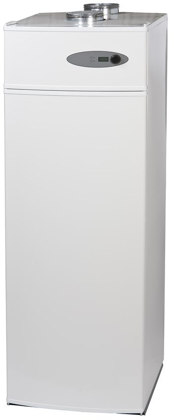
6DESIGN & DIMENSIONS OF VT2130 / VT2131 / VT2132:
1. Air outlet 14. Insulation foam
2. Evaporator 15. Heating coil (lower)*
3. Compressor 16. Heating coil inlet (lower)*
4. Air inlet 17. Heating coil outlet (lower)*
5. Enameled container 18. Circulation
6. Pocket for sensor - Thermometer 19. Hot water outlet
7. Anode 20. Defrost water outlet
8. Electrical heating element 22. Fan
9. Pocket for sensor – working phial 32. Heating coil (upper)**
10. Anode* 33. Heating coil inlet (upper)**
11. Adjustable feet 34. Heating coil outlet (upper)**
12. Cold water inlet
13. Alu condenser *Only VT2131 and VT2132
**Only VT2132
CONTROL PANEL
29. Control button push/rotary
30. Control panel (display)
31. Operating-/alarm lamp heat pump
32. Operating-/alarm lamp supplementary heating
INTEGRATED HEAT-FXCHANGER (COIL):
The DHW HP con be equipped with 1 (e.g. model VT2131) or 2 integrated heat exchangers (coils). The single coil versing
has a heat-exchange surface of 1m2 (20), whereas the double coil version has 1.5 m2 for the lower (20) and 0.6 m2 for the
upper (17) coil. If you are using supplementary heating from 2 different energy sources, for example solar-thermic and oil /
gas/ solid fuel boiler, the solar installations must be connected to the lower coil. For the 2-coil version and 1 supplementary
energy source (e.g. solar-thermic) it is also possible to connect both coils in series.
NOTE: The temperature in the tank must not exceed 65°C. This must be ensured by a safety device controlled by the
maximum DHW temperature in the tank (1st priority) and a temperature limiter on the inflow side. Overheating the tank
might damage the heat pump's refrigerant circuit and is not covered by the product warranty.
7INSTALLATION
CHOICE OF THE INSTALLATION LOCATION:
Wherever possible, the heat pump should be installed close to the existing hot-water conduit.
The location must be indoors in a frost-free environment with a frost protected sewer drain. The floor at the location must be
flat and at level. Minor irregularities can be levelled by means of the adjustable feet. It has to support the weight of the DHW
HP (approx. 430 kg filled). The location must be designed to support the corresponding load. If the HP will operate mostly
on off peak hours do not install the product near to bedrooms. Even if the DHW HP operates very silently, this might
disturb sensible users. Please ensure that the location and the DHW HP are easily accessible for maintenance and service.
All damages and service impossibilities (e.g. repair), due to the reduced accessibility are part of the installer/user
responsibility and not covered by the manufacturer’s warranty.
NOTE: State-of-the-art building regulations, standards and legal requirements must be observed.
Unused connectors (Coil, recycling loop) have to be sealed and insulated properly in order to avoid heat losses.
The DHW HP works either with ambient air or outside air. Independent of the installation mode there are some basic
requirements for the air quality of the airflow:
- The air must be dust and grease free
- The air source should benefit from free energy gains like in the laundry (dryer waste energy), kitchen,
garage (appliances and car waste energy), basement (geothermal energy) and heating cabinet.
- The air temperature must be > -10°C
- The air source can benefit from dehumidification
- The exhaust air is cooled down and can be used for cooling e.g. a wine cellar
The easiest way to install the DHW HP is the ambient air installation:
In the ambient air mode the product doesn’t need ducting. The air inlet uses the ambient air of the location and the air outlet
exhausts the air into the same room. This installation mode needs some requirements:
- Room volume > 20 m3
- Free air flow, no air re-circulation (air short-circuit between inlet and outlet
- Ventilation of the location (air inflow > 200 m3/h
- Location must not be heated by a heating system
In this installation mode the fan speed should be adjusted at “high”. Anyhow, if you should want to change the fan speed for
comfort reasons to “low”, you can do so without a considerable decrease of performance.
Semi ducting or full ducting can increase the efficiency. In this way you can optimise the airflow and the efficiency.
- Semi ducting is usually used for the exhaust side to avoid mixing ambient and exhausts air.
- Semi ducting helps to reduce the noise level
Full ducting on air inlet and air outlet gives the possibility to position air inlet and outlet independent of the DHW HP
location. Full ducting is also recommended for the use of exterior air.
In this installation mode the fan speed should be adjusted at “high”.
It is also possible to use the DHW HP ducted with extracted air. For this special application the minimum air flow
requirements of the HP have to be matched with the airflow design of the ventilation.
The fan speed for permanent operation can be selected separately.
For more details see “air connections – ducting”
PREPARATION FOR INSTALLATION:
The heat pump is delivered adjusted and ready assembled with wire and plug. Just connect the water inlet and outlet to the
piping. The defrost water from the evaporator is evacuated by a drain (13) and has to be connected to the sewer. The
dimensions of the DHW HP and the connections see “design & dimensions”.
General rules for hydraulic connection:
Your DHW HP has a high quality steel tank for the DHW generation. This tank inside is enamelled and gives you a perfect
protection against corrosion in combination with an additional catholic protection (magnesium anode). Nevertheless, in
order to protect the tank and also the connectors you have to avoid connecting copper pipes to steel or galvanized steel
fittings directly (in flow direction). The use of insulation fittings is mandatory in this case.
NOTE: The installation must be done according to the state of the art of installation. The non-respect of these rules and
abnormal water composition may be the reason of warranty exclusion. The manufacturer has no liability for the installation
and possible damages to it.
8HYDRAULIC INSTALLATION
The installation and the first launch of the DHW HP have to be made by a qualified and authorised installer according to
the instructions and recommendations of this manual. The respect of the manufacturer’s instructions, as well as the respect
of the actual local, national and international standards, regulations and laws as well as the state-of-the-art regarding water
and electrical installations is mandatory and part of the warranty requirements
COLD WATER CONNECTION:
The DHW HP core is a pressure tank intended for multiple outlets. The hydraulic connections have to be made in
accordance with the local, national and international regulations and standards. Generally the water inlet is protected by a
safety device (safety valve and drain combined) as well as a backflow protection (retention valve) and a shut-valve. These
fittings are not included in the delivery. The use of approved new fittings is mandatory. If the supply pressure is > 5 bar
DHW connection:
Please resect the legal an specially hygienic requirements for DHW and the restrictions given by the use of different
installation material. The DHW HP might be used as unique or additional source for the generation of DHW.
NOTE: The heat pump should only be launched when you are e sure that the tank is completely filled with water. At first
launch (or when the tank has been drained) the heat-up time (ambient air temperature of approx. 15°C, DHW temperature
45-55°C) is likely to be 8 to 10 hours. Choose the HP operating mode to start, perhaps in combination with the
supplementary heating.
INSULATION OF THE INSTALLATION:
All pipes and fittings and connectors on the DHW side must be insulated to prevent heat loss. Unused connectors have to be
sealed and insulated.
NOTE. The proper insulation measures are mandatory for an efficient operation of the DHW HP. The non-respect of these
rules might be the origin of customer complaints.
9COLD WATER CONNECTION SCHEME:
1: Cold water inlet
2: Ball valve 1”: must be open during operation.
3: Contra valve 1”: to prevent excessive pressure.
4: Safety valve 1”: max. pressure 1 MPa / 10 bar. Discharge pipe connected to safety valve must be installed downwards and
in frost free environment.
5: Drain valve 1”: open when the boiler needs to be emptied.
6: Hose connections: for drainage of water from safety valve and drain valve.
7: Drain: connect hoses to safety valve and drain valve and lead the water into drain.
5
3
2
1
6 4
7
957085-01
CIRCULATION (RECYCLE LOOP) CONNECTION:
We recommend not to use the circulation (recycle loop), because of the important heat losses. This might be the origin of
customer complaints.
If you have to use a recycle loop anyway because of comfort reasons, or building regulations (e.g. “the 3 litre rule”) the
piping and the connectors must be dimensioned and insulated carefully. We advise to operate the recycle loop pump
intermittent by means of a timer or a special circulation pump controller, which triggers the pump operation when DHW is
needed and memorizes the user profile. The position of the circulation connector avoids the propagation of scale into the
recycle loop. If required by building regulations, heat loss compensation with self-regulating heating cables is possible.
DHW PRODUCTION:
Your DHW HP can generate DHW with different energy sources, such as HP, electrical heater (built-in), boiler or a solar-
thermic installation. Heating of domestic water can be made using the heat pump, electrical heater and / or boiler. Electrical
heater (built-in), boiler and solar-thermic installation are referred to as supplementary heating. The energy sources are
selected in the menu. They can be selected individually or in combination of 2 sources, but never boiler and electrical heater
together.
The desired set point temperature for DHW can be adjusted by the user in the parameter menu in between 5°C and the
installation specific maximum temperature Tmax (installer setting).
10Tmin is the set point for supplementary heating, It can be adjusted independently of the DHW set point, The factory setting
for DHW set point “SETPOINT” is 55°C and for “Tmin” 35°C.
The set point temperature can be achieved either by the HP (energy source selection “HP”, “HP + EL”, “HP + boil”) or the
supplementary heating (energy source selection “EL”, “boil”), depending on the choice of the energy source. Tmin is
achieved with heat pump and supplementary heating (energy source selection “HP + EL”, “HP + boil”), if selected.
The heat pump operates with a hysteresis of +1 -3 °C around the DHW set point. The supplementary heating operates with a
hysteresis of + -1 °C.
The DHW HP is equipped with a permanent and an automatic defrosting system. This reduces the need for defrosting and
increases efficiency (increased operation cycle). Nevertheless it is normal, that (especially at low temperatures and in heavy-
duty operation) he evaporator has to undergo a de-icing procedure. When the evaporator temperature gets too low the heat
pump will stop and the defrosting procedure starts automatically. For air defrosting this limit is -8 °C, for hot-gas defrosting
-18 °C. Normal operation resumes at an evaporator temperature of +5 °C.
The LED indicators 29 and 30 of the control panel show the actual operation mode, the upper LED(29) for the heat pump
and the lower LED (30) for supplementary heating:
• Off: Inactive (not selected)
• Orange: Selected, but running standby mode
• Green: Selected and producing DHW.
ELECTRICAL INSTALLATION:
The heat pump is equipped with a 2 metre power supply cord, 3 x 1.5 mm2, which comes out on the back of the device with
stress relief and a safety plug.. The socked should be protected individually by an automatic circuit breaker and a residual-
current circuit breaker (30mA)
Max. power input: see “page 4 - technical data”.
Power supply_ 230V AC single-phase, 50Hz
Mains lead colours: phase – brown, neutral – blue, earth – yellow/green
NOTE: The appliance must be installed in accordance with national wiring regulations by a qualified and authorized
installer. If the supply cord is damaged, it must be replaced by the manufacturer, its service agent or similarly qualified
personnel in order to avoid a hazard.
11WIRING DIAGRAM:
ELECTRONIC DHW HP CONTROLLER
USER INTERFACE:
2-line display (The Control Panel setup, see also control panel drawing on page 7).
Water The upper line displays the parameter menu (function).
45°°C The bottom line displays the parameter status or value.
The display is activated (indicated) by turning or pressing the rotary-/push button (no. 32 on the control panel drawing).
To scroll through the menu turn the rotary-/push button.
You have 12 menus. The far left is the menu ”WATER” (indicates the actual DHW temperature).
If you want to change the status or value of a parameter, push shortly the rotary-/push button; the status/value line will now
start flushing. While the display is flushing you can vary the status/value by turning the rotary-/push button. When the
desired value is indicated push the rotary-/push button again to acknowledge the chosen status/value. If you don’t
acknowledge the value while the display is flushing, the status/value remains unchanged.
If you press t the rotary-/push button for more than 3 seconds, you get to the service parameter menu. This expert menu is
reserved for the installer. Please do not change these settings without consulting your installer. None authorized settings in
this menu might be the cause of warranty exclusion.
12DISPLAY VIEW:
MAIN PARAMATER MENU
Language When power is connected for the first time this parameter appears on the display. Factory setting: ENGLISH.
English You can choose between: Danish, German, English, Spanish, French, Polish, Slovene, and Italian by
pushing the control button while the value line is flushing. You can change the language settings at every
moment in the installer menu (service parameter menu).
Water If the power is switched on, this parameter appears on the display.
45°C It indicates the current DHW temperature
Evapor Evaporator temperature.
5°C This parameter displays the current evaporator temperature
Alarm Alarm display.
0 0 0 This parameter displays up to 3 alarms. "0" = no alarm. The alarm types 1 to 10 are described in the alarm
overview in the following pages.
Alarms are acknowledged and reset by pushing the rotary/push button.
Status This parameter displays the current operating mode of the DHW HP.
Off The possible operating mode values are:
"Off" = switched off,
"Standby", waiting for DHW demand
"H.Water " = DHW production on going ,
"Def.Gas" – "Def.Air" - "Def.Stop” = Defrosting condition (see page 14), "alarm".
Setpoint This parameter displays the set point temperature for DHW.
45°C The set point of the DHW temperature can be adjusted in between 5°C and Tmax by pressing and releasing
the rotary/push button (parameter selection). While the value line is flushing, the value can be adjusted by
turning the rotary/push button. Press again the rotary/push button to acknowledge and memorize your
choice. The recommended DHW set point temperature is between "45°C" and "55°C". Note! This is only
an average temperature and not the hot water output temperature.
T min This parameter displays the minimum temperature. Tmin is the temperature level that triggers the operating
of the supplementary heating (if selected as "Heat pump" parameter value, e.g. "HP+EL" or “HP+Boil” if
installed).
35°C The minimum temperature can be adjusted in between 5°C and Tmax by pressing and releasing the
rotary/push button (parameter selection). While the value line is flushing, the value can be adjusted by
turning the rotary/push button. Press again the rotary/push button to acknowledge and memorize your
choice. The recommended minimum temperature is "35°C"
T2 min Similar function as T min, used for “holiday function” or when the DHW HP is in “standby” mode. Tmin
10°C protects the DHW HP and your installation against freezing. The factory setting is “10°C”.
Heat This parameter displays the energy source for your DHW production.
pump The energy source can be selected with the rotary/push button. The possible selections are
HP+EL "OUT", "HP", "EL", "HP+EL","BOILER", "HP+BOIL".
If no boiler is installed, the last 2 combinations are not to be used
Legionel This parameter displays status of the automatic Legionella protection mode.
Off If activated ("ON") the DHW HP will once a week increase the DHW temperature to 65°C, in order to
avoid possible bacteria (legionella) creation.
FanCon This parameter displays the fan operation mode, when in the HP is in standby operating mode.
Off If this parameter is unselected ("Off") the fan will stop together with the HP. If this parameter is set to
"Low" for low or "High" for high speed, the fan will operate permanently and accordingly, while the HP is
in the “standby” operating mode (= constant ventilation). Factory setting “OFF”.
FanOper This parameter displays the fan speed, when the HP is in operating mode. The fan speed can be selected with
High the rotary/push button. The possible selection are
"Low" = low speed
"High" = high speed
Solarcel This function permits to operate the DHW HP with cheap and environmentally friendly energy from your
Off own solar cell panels.
"Off" = Solar cells are not connected to system or not chosen to be used by the user.
"HP only" , “EL only” and “HP + EL”: These values indicate the chosen operation mode, when the solar
cell function is activated by the external inverter signal,
see “page 12 wiring diagram for connection to controller.
SC-HP 5°C – T max
52°C Set point temperature of “HP only “operating mode, when Solcel function activated (inverter signal)
SC-EL 5°C – T max
1353°C Set point temperature of “EL only “ or “HP + EL” operating mode, when Solcel function activated (inverter
signal)
Holiday This parameter activates/deactivates the holiday mode. The holiday mode can be selected with the
Off rotary/push button. The possible selection are:
“Off”, “1 week”, “ 2 weeks”, “3 weeks”, “3 days”, “Manual”
When the holiday mode is activated, “T2 min” is the safety level for frost protection..
Man.days This parameter displays the number of holidays at individual (manual) choice. The holiday days can be
1 selected with the rotary/push button. The possible selection are:
1-99
ReDays This parameter displays status of the remaining number of holidays. The possible values are
0 0-99
Boost This parameter activates/deactivates the BOOST operating mode in the case of additional need for DHW. If
Off the BOOST operating mode is activated “ON”, the DHW production will be made by the HP and the
supplementary electrical heating either for a maximum cycle of 1 hour or if Tmax is reached. Possible
values
“Off”, “On”. The factory setting is “OFF”.
FanPause “Off”, “30m/15s”, “30m/30s” , “60m/15s”, “60m/30s” , “90m/15s”, “90m/30s”
30m/30s When activated the fan will stop for either 15 or 30 seconds every 30m, 60m or 90m, according to the
selected value.
SERVICE MENU
ONLY FOR THE INSTALLER
Language Danish, German, English, Spanish, French, Polish, Slovene, Italian
English
Software SERVICE MENU – Only for the installer.
1.35 The menu "software" indicates the software release.
The number "1.35" is the actual release
Defrost SERVICE MENU – Only for the installer.
Gas This parameter displays the selected defrosting mode. Attention: The defrosting mode is model
specific and must not be changed without written consent of the manufacturer.
The possible selections are:
"GAS", for VT2130 / VT2131 / VT2132
Service Def.None, Def.Gas
Anode SERVICE MENU – Only for the installer.
Off “Off”, “On”
Is activated if signal anode is factory installed or can be activated if signal anode is retrofit.
T max SERVICE MENU – Only for the installer
55°C Maximum operating "T max". This parameter value limits the maximum operating temperature. Here
can the maximum desired operating temperature be adjusted. ".
”T max” can be adjusted in between 5°C and 62°C. The DHW set point temperature cannot exceed
Tmax. Please note, that efficiency of the heat pump is reduced at higher temperatures = higher energy
consumption.
Compressor protection: After each compressor stop, a new start is delayed at least 5 minutes.
FAN CONTROL:
The fan has 2 speed settings, which can be adjusted in the menu "FanOper". The factory setting for the parameter value is
“high”. We recommend this setting for best performance. Nevertheless, if necessary, the “low” speed setting can be used to
improve acoustic comfort or to avoid acoustic interferences without a significant loss of performance. (Installation not
ducted on ambient air).
If your air outlet and/or air inlet are ducted, it is mandatory to set the “FanOper” parameter value to “High”.
The menu parameter "FanCon” controls the fan-operating mode for the use with constant ventilation. If this parameter is
unselected ("Off") the fan will stop together with the HP. If this parameter is set to "Low" for low or "High" for high
speed, the fan will operate permanently and accordingly, while the HP is in the “standby” operating mode (= constant
ventilation). Factory setting “OFF”.
Note: The design of an integrated constant ventilation system has to b done under the responsibility of an expert specified in
order to match air flows. The manufacturer declines all responsibility on such a design.
14Vous pouvez aussi lire