VT Actionneur électrique - Copie.pub
←
→
Transcription du contenu de la page
Si votre navigateur ne rend pas la page correctement, lisez s'il vous plaît le contenu de la page ci-dessous
VT
Actionneur électrique

   FR   Manuel d’Installation et d’Utilisation
   UK   Installation and Operation Manual
   DE   Installations- und Bedienungsanleitung
   ES   Manual de instalación y funcionamiento

                                  Indice de protection   Facteur de marche   Anticondensation
                          600Nm                                                   intégrée

                                  IP68                   50%
                                                                             Anticondensation
                                  Enclosure protection      Duty cycle            heater

Valpes.com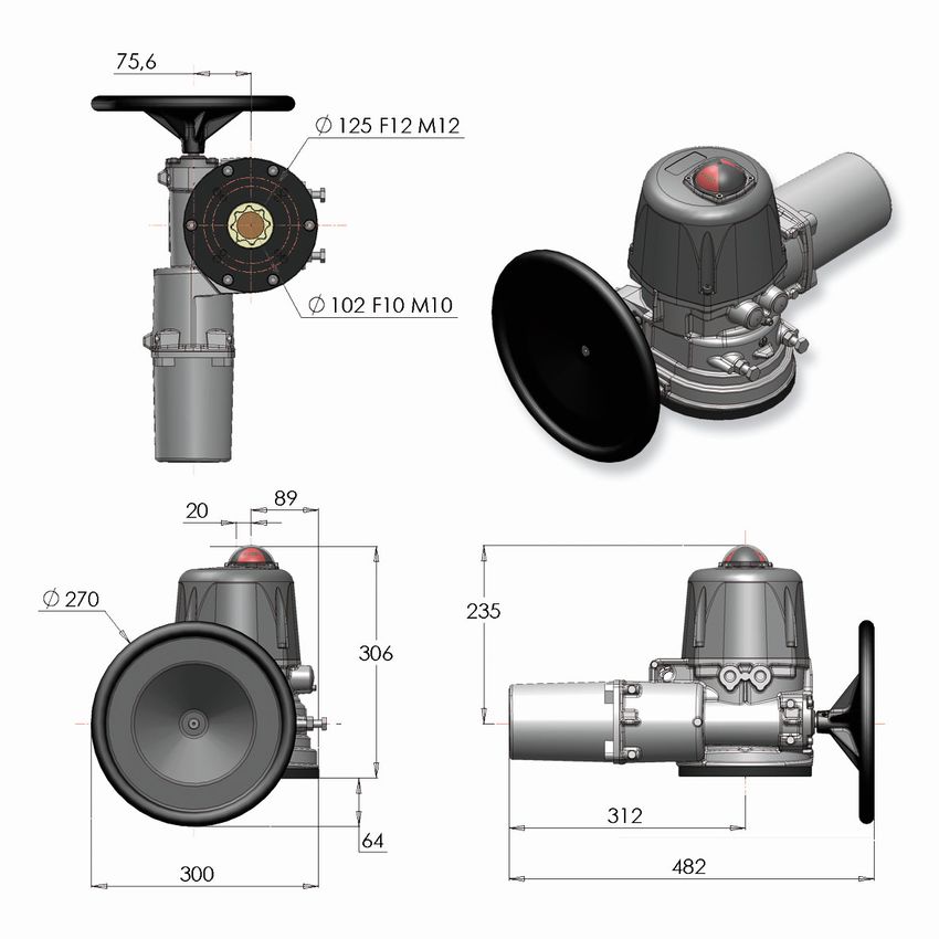
FR FRANÇAIS Français ...................................................................................................................... 2 English .......................................................................................................................12 Deutsch .....................................................................................................................22 Español ......................................................................................................................32 Index Informations générales.................................................................................................. 3 Description Transport et stockage Maintenance Garantie Retour de marchandises Consignes de sécurité Description des actionneurs ........................................................................................ 4 Encombrements ............................................................................................................ 5 Commande manuelle de secours ................................................................................. 5 Branchements électriques ............................................................................................ 6 Avertissements Instructions de câblage Schémas électriques Données techniques.....................................................................................................10 Ce produit est conforme à la directive européenne 2012/19/UE sur les déchets d’équipements électriques et élec- troniques (DEEE). Ne jetez pas ce produit avec vos déchets ménagers, recyclez-le conformément à la législation de votre pays en le jetant séparément dans un bac de tri spécialement conçu à cet effet. 2 DSBA3002 • Rév. 24/01/2019
FRANÇAIS FR
DESCRIPTION
Les actionneurs électriques VALPES ont été conçus pour permettre le pilotage d’une vanne 1/4 tour. Pour tout autre appli-
cation, nous consulter préalablement. Nous ne pouvons être tenus responsables en cas d’autre utilisation.
TRANSPORT ET STOCKAGE
Les transporteurs étant responsables des avaries et des retards de livraison, les destinataires doivent émettre des ré-
serves, le cas échéant, avant de prendre livraison des marchandises. Les envois directs d’usine sont soumis aux mêmes
conditions.
Le transport sur site est effectué dans un emballage rigide.
Les produits doivent être stockés dans des endroits propres, secs et aérés, de préférence sur des palettes de manuten-
tion ou sur des étagères.
MAINTENANCE
La maintenance est assurée par notre usine. Si le matériel ne fonctionne pas, vérifier le câblage suivant le schéma élec-
trique et l’alimentation de l’actionneur électrique concerné.
Pour toute question, prendre contact avec le service après-vente.
Pour nettoyer l’extérieur de l’appareil, utiliser un chiffon et de l'eau savonneuse : NE PAS UTILISER D'AGENT A BASE
DE SOLVANT OU D'ALCOOL
GARANTIE
Tous nos produits sont soigneusement testés et réglés en usine.
Ces produits sont garantis 3 ans ou 50000 manœuvres contre tous vices de fabrication et de matière, à partir de la date
de livraison usine (facteur de service et classe du modèle suivant la norme CEI34).
La garantie couvre exclusivement le remplacement ou bien, à notre discrétion exclusive, la réparation gratuite des parties
composant la marchandise fournie qui, sur avis sans appel, se révèlent défectueuses à l’origine pour des vices de fabri-
cation attestés.
La présente garantie exclut les dommages dérivant de l’usure normale ou de frictions et ne s’applique pas aux parties
éventuellement modifiées ou réparées par le client sans notre autorisation préalable et pour lesquelles nous n’accepte-
rons aucune demande de dédommagement, que ce soit pour dommages directs ou indirects (consulter notre site web
pour tout détail à ce sujet).
La garantie ne couvre pas les conséquences d'immobilisation et exclut tout versement d'indemnité. Les accessoires,
consommables (batteries...) et adaptations ne sont pas couverts par cette garantie. Au cas où le client n'aurait pas réali-
sé ponctuellement les paiements stipulés aux échéances convenues, notre garantie sera suspendue jusqu'au paiement
des échéances en retard et sans que cette suspension puisse augmenter la durée de la garantie à la mise à disposition
Toutes les ventes de produits sont sujettes à nos conditions générales de vente, publiées sur notre site Internet.
RETOUR DE MARCHANDISE
L'acheteur est tenu de vérifier au moment de la livraison la conformité de la marchandise par rapport à sa définition.
L'acceptation par l'acheteur de la marchandise dégage le fournisseur de toute responsabilité, si l'acheteur découvre une
non-conformité postérieurement à la date d'acceptation. Dans un tel cas, les frais de mise en conformité seront à la
charge de l'acheteur qui supportera également seul, les conséquences financières du dommage. Les retours des mar-
chandises sont acceptés que si nous les avons préalablement autorisés : ils doivent nous parvenir franco de tous frais à
domicile et ne comporter que des produits dans leur emballage d’origine. Les marchandises rendues sont portées au
crédit de l'acheteur, déduction faite des 40% de reprise du matériel calculé sur la base du montant initial des marchan-
dises retournées.
CONSIGNES DE SECURITE A lire avant toute installation du produit
Toute intervention doit être effectuée par un électricien qualifié ou une personne formée aux règles d’ingénierie élec-
trique, de sécurité et tout autre directive applicable.
Respecter impérativement l’ordre des consignes de raccordement et de mise en service décrites dans le manuel sans
quoi le bon fonctionnement n’est plus garanti. Vérifier les indications portées sur la plaque d’identification de l’action-
neur : elles doivent correspondre à votre réseau électrique d’alimentation.
CONSIGNES DE MONTAGE A lire avant toute installation du produit
DSBA3002 • Rév. 24/01/2019 3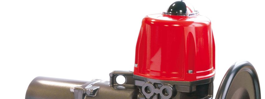
FR         FRANÇAIS

Description des actionneurs

             1

                                                                                               D
             2

             3                                                                                                       4
                                                                                                  A

                                                                                                                     5
                                                                                                                     7
             6
                                                        C                                                            8

                                                                                                                 10
         11
                                                                                                                     9

         12                                                                                     B

     Pièce         Description                              Pièce        Description
                                                                         Trous taraudés M20x1,5
                 1 Indicateur visuel de position                     7
                                                                         (1/2’’ NPT en option)
                 2 Capot                                             8 Presse-étoupe
                 3 Contacts de détection moteur + recopie            9 Vis de terre
                 4 Cames                                            10 Butées mécaniques
                 5 Moteur                                           11 Volant
                 6 Joint torique                                    12 Platine fonte F10-F12
                 A CHC M8 x 30 A2-70                                B CHC M8 x 20 A2-70
                 C CHC M6 x 16 A2-70                                D CHC M6 x 30 Classe 12.9

 4                                                                                      DSBA3002 • Rév. 24/01/2019
FRANÇAIS FR
Encombrements
Douille
Étoile (mm) Profondeur (mm) Fixation ISO F Diamètre (mm) Taraudé M Profondeur (mm) Nombre de vis
36 41 F10 102 M10 25 4
F12 125 M12 30 4
Longueur max. des vis (+ hauteur de la platine de fixation de la vanne)
F10 20mm
F12 25mm
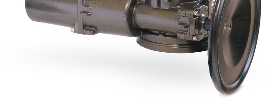
Commande manuelle de secours et réglage des butées
Les butées mécaniques sont réglées par défaut à 90° et collées (Tubétanche Loctite 577 ou équivalent). Il est possible de les
ajuster en déplaçant les 2 vis (annexe p.10 rep.10) mais il faut les recoller pour assurer une bonne étanchéité.
Montage / démontage du capot et de l’indicateur
Il est nécessaire de démonter le capot pour le câblage et le réglage de l’actionneur.
Montage du capot (annexe p.4 rep.2) : s’assurer que le joint (annexe p.4 rep.6) est bien dans son logement, graisser le plan de
joint (graisse Molydal 3790 ou équivalent), monter le capot et serrer les 4 vis M6 (annexe p.4 rep.D, couple : 6Nm).
Montage de l’indicateur visuel (annexe p.4 rep.1) : monter le joint et l’indicateur puis le hublot avec les 4 vis M4.
Mettre hors tension avant d’utiliser la commande manuelle
DSBA3002 • Rév. 24/01/2019 5
FR FRANÇAIS
Branchements électriques
Avertissements
Tension Terre de Tension Tension
dangereuse protection continue alternative
N’utiliser au maximum qu’un seul relais par actionneur.
Le branchement à une prise de Terre est obligatoire au-delà de 42V suivant la norme en vigueur.
L'actionneur étant branché en permanence, il doit être raccordé à un dispositif de sectionnement (interrupteur,
disjoncteur), assurant la coupure d'alimentation de l’actionneur, placé près de l’actionneur, facilement accessible
et marqué comme étant le dispositif de coupure de l'appareil.
La température du bornier peut atteindre 90°C.
Afin d’optimiser la sécurité des installations, le câblage du report défaut (D1 et D2) est fortement conseillé.
Pour une utilisation avec de grandes longueurs de câbles, le courant induit généré par les câbles ne doit pas dé-
passer 1mA.
L'actionneur accepte les surtensions temporaires survenant sur le RÉSEAU d'alimentation jusqu'à ±10 % de la
tension nominale.
Sélection des câbles et des entrées de câble : La température de service maximale des câbles et presse-étoupes
ne doit pas être inférieure à 110°C.
Il est impératif de raccorder tous les actionneurs à une armoire électrique. Les câbles d'alimentation doivent être
de calibre ASSIGNÉ pour le courant maximal prévu pour l'appareil et le câble utilisé doit être conforme à la CEI
60227 ou CEI 60245.
Pour assurer une étanchéité IP68, les presse-étoupe doivent être utilisés (câbles de 7 à 12mm). Dans le cas con-
traire, remplacer les presse-étoupe par des bouchons ISO M20 IP68. Un presse-étoupe est considéré étanche
quand il est serré d’un tour après contact entre le manchon et l’écrou extérieur.
Les fins de courses auxiliaires doivent être connectés avec des câbles rigides. Si la tension appliquée est supé-
rieure à 42V, l'utilisateur doit prévoir un fusible dans la ligne d'alimentation.
Les tensions appliquées à chaque contact de recopie doivent impérativement être les mêmes. L’isolation renfor-
cée par rapport au control moteur, autorise des tensions jusqu’à 250V AC/DC.
6 DSBA3002 • Rév. 24/01/2019FRANÇAIS FR
Branchements électriques : instructions
CABLAGE DE L’ALIMENTATION ET DE LA COMMANDE
Retirer l’indicateur visuel, dévisser les 4 vis et retirer le capot.
Vérifier sur l’actionneur que la tension indiquée sur l’étiquette correspond à la tension du réseau.
Connecter les fils sur le connecteur suivant le mode de pilotage souhaité. (Voir schéma p.8/9)
Pour garantir le bon fonctionnement de la résistance anti-condensation, l’actionneur doit être alimenté en permanence
CABLAGE DE LA RECOPIE
Nos actionneurs sont par défaut équipés de 2 contacts fins de course auxiliaires secs, soit normalement ouverts, soit normalement
fermés (voir schéma électrique DSBL0491 (230V) et DSBL0492&DSBL0493 (400V) à l’intérieur du capot). Par défaut, la came
blanche est utilisée pour détecter l’ouverture (FC1) et la came noire pour détecter la fermeture (FC2).
Les fins de courses auxiliaires doivent être connectés avec des câbles rigides. Si la tension appliquée est supérieure à 42V, l'utilisa-
teur doit prévoir un fusible dans la ligne d'alimentation.
Dévisser le presse-étoupe droit et passer le câble.
Enlever 25mm de gaine et dénuder chaque fil de 8mm.
Connecter les fils sur le bornier suivant le schéma p. 8/9.
Revisser le presse-étoupe ATEX/IECEX et IP68 (s’assurer du bon remontage de celui-ci afin de garantir une bonne étanchéité).
REGLAGE DES CONTACTS FINS DE COURSE
L’actionneur est préréglé en usine. Ne pas toucher les 2 cames inférieures sous peine de perturber le fonctionnement de l’actionneur
voire d’endommager ce dernier.
Pour ajuster la position des contacts auxiliaires, faire pivoter les 2 cames supérieures en utilisant la clé appropriée.
Remonter le capot et visser les 4 vis.
DSBA3002 • Rév. 24/01/2019 7FR FRANÇAIS
Schéma électrique 230V
La température du bornier peut atteindre 90°C
Les câbles utilisés doivent être rigides (tensions pour la recopie : 4 à 250V AC/DC)
Rep. Désignation Rep. Désignation Rep. Designation
FCO Fin de course ouverture FCF Fin de course fermeture TLO Contact couple : ouverture
FC1 Fin de course auxiliaire 1 FC2 Fin de course auxiliaire 2 TLF Contact couple : fermeture
C Condensateur F Contact thermique moteur H Résistance anti-condensation
M Moteur VL Violet MR Marron
RG Rouge NR Noir BU Bleu
OG Orange BC Blanc D1/D2 Bornier report défaut (230V AC max / 5 A )
ALIMENTATION ET COMMANDE
N Ph N Ph
Ouvrir Fermer
RECOPIE
TP/PE
1 2 3 D1 D2 4 6 5 7 8 9 10 11
FC2
H
A1
FC1
SNAA950000
A2
VL
A
MR
C M~
TLF FCF B
RG
230V
NR LS
BU
C F
OG
TL0 FCO D
BC
BC
8 DSBA3002 • Rév. 24/01/2019FRANÇAIS FR
Schéma électrique 400V triphasé
La température du bornier peut atteindre 90°C
Les câbles utilisés doivent être rigides (tensions pour la recopie : 4 à 250V AC/DC)
Rep. Désignation Rep. Désignation Rep. Designation
FCO Fin de course ouverture FCF Fin de course fermeture TLO Contact couple : ouverture
FC1 Fin de course auxiliaire 1 FC2 Fin de course auxiliaire 2 TLF Contact couple : fermeture
BC Blanc F Contact thermique moteur H Résistance anti-condensation
M Moteur VL Violet MR Marron
RG Rouge NR Noir BU Bleu
OG Orange D1/D2 Bornier report défaut (230V AC max / 5 A )
COMMANDE (230V AC)
KM1 : Ouvrir
N L1 KM2 : Fermer
ALIMENTATION (400V triphasé 50Hz)
N L1 L1 L2 L3
KM1
KM2
KM1 KM2 RECOPIE
T/E
1 2 3 A1 D1 D2 4 6 5 7 8 9 10 11
KM2
KM1
FC2
H
SNAA950000 FC1
A2
VL
RG
OG
TLF FCF MR
D
BC
A
F M NR
B
TL0 FC0
LS
BC BU
C
i L’alimentation du moteur est câblée sur un relais bistable triphasé à inversion de phase (non livré)
En cas de fonctionnement inverse, inverser deux des phases du moteur
DSBA3002 • Rév. 24/01/2019 9FR FRANÇAIS
Caractéristiques techniques
VT600 VT1000
Implantation
Carter : Aluminium + peinture EPOXY / capot : PA6 UL 94 V-0 ou Aluminium + peinture EPOXY
Matériaux
Entraîneur : acier + traitement Zn / Axes et vis : inox
Étanchéité IP68
Utilisation intérieur et extérieur (emplacements humides acceptés)
Température d’utilisation -20°C à +70°C
Altitude d'utilisation Altitude jusqu’à 2000m
humidité relative maximale de 80% pour des températures jusqu'à 31°C, et
Hygrométrie
décroissance linéaire jusqu'à 50% d'humidité relative à 40°C
applicable à l’environnement prévu
Degré de pollution
(DEGRÉ DE POLLUTION 2 dans la plupart des cas)
Poids 25kg
Données mécaniques
Couple nominal 450Nm 600Nm
Couple maximal 600Nm 1000Nm
Temps de manœuvre 42s 65s
Plage angulaire 90° (180°-270° sur demande)
Facteur de marche 50%
Entrainement selon ISO5211 Étoile 36 (profondeur 41mm) • F10/F12 (profondeur F10 : 25mm / F12 : 30mm)
Commande manuelle Volant sécurisé sans débrayage
Données électriques
Tensions1) 230V AC (50/60Hz) • 400V triphasé
SURTENSIONS TRANSITOIRES jusqu’aux niveaux de la
Catégorie de surtensions2)
CATÉGORIE DE SURTENSION II
Puissance 250W
Courant nominal 10 à 12A
Limiteur de couple Mécanique
Nombre de contacts de recopie 2 (4 en option)
Tension maximale des contacts de fins de
4 à 250V AC/DC (Surtension catégorie II)
course
Courant maximal des contacts de fins de
1mA à 5A max
course
Résistances anticondensation 10W
1) L’actionneur accepte les fluctuations de la tension du RÉSEAU d'alimentation jusqu'à ±10 % de la tension nominale.
2) Accepte les surtensions temporaires survenant sur le réseau d’alimentation.
10 DSBA3002 • Rév. 24/01/2019FRANÇAIS FR DSBA3002 • Rév. 24/01/2019 11
UK ENGLISH Français ...................................................................................................................... 2 English .......................................................................................................................12 Deutsch .....................................................................................................................22 Español ......................................................................................................................32 Index General information ......................................................................................................13 Description Transport and storage Maintenance Warranty Return of goods Safety instructions Actuators description ..................................................................................................14 Dimensions ...................................................................................................................15 Emergency manual override ........................................................................................15 Electric wiring ..............................................................................................................16 Warnings Wiring Instructions Electric diagrams Technical data ..............................................................................................................20 This product meets the European Directive 2012/19/UE about electrical and electronic equipment (DEEE). It mustn't be mixed with common waste. Please, recycle or dispose of them according to your country laws. 12 DSBA3002 • Rév. 24/01/2019
ENGLISH UK
DESCRIPTION
These electric actuators have been designed to perform the control of a valve with 90° rotation. Please consult us for any
different application. We cannot be held responsible if the mentioned actuators are used for any other purpose.
TRANSPORT AND STORAGE
The forwarding agents being held as responsible for damages and delays of the delivered goods, the consignees are
obliged to express if applicable their reserves, prior to accept the goods. The goods delivered directly ex works are sub-
ject to the same conditions.
The transport to the place of destination is carried out by using rigid packing material.
The products must be stored in clean, dry, and ventilated places, preferably on appropriate palettes or shelves. Actua-
tors should not be stored upside down.
MAINTENANCE
Maintenance is ensured by our factory. If the supplied product does not work, please check the wiring according to the
electric diagram as well as the power supply of the electric actuator in question.
For any question, please contact our after-sales service.
To clean the outside of the actuator, use a lint and soapy water. DO NOT USE ANY CLEANING PRODUCT WITH SOL-
VENT OR ALCOHOL.
WARRANTY
Our products are thoroughly tested and set in factory.
These products are 3-year warranty from the manufacturing site delivery date or 50,000 actuations against all types of
manufacturing and material faults (operating time and model class according to standard CEI34).
The said guarantee covers solely replacement or – at our full sole discretion - repair, free of charge, of those components
of the goods supplied which in our sole view present proven manufacturing defects.
This warranty excludes any damage due to normal product usage or friction and does not include any modified or unau-
thorized repair for which we will not accept any request for damage (either direct or indirect) compensation (for full details
see our website).
The guarantee does not cover the consequences of breakdown and excludes any payments for indemnities. The acces-
sories, consumables (batteries…) and adaptations are excluded from the guarantee. In the case where a customer has
not proceeded to payments within the agreed period, our guarantee will be suspended until the delayed payments have
been received and with the consequence that this suspension will not prolong the guarantee period in any case.
All sales subject to our terms to be found on our website.
RETURN OF GOODS
When the actuator receives his actuator, he must check its conformity according to its definition.
The acceptance of the goods by the purchaser disclaims the supplier of all responsibility if the purchaser discovers any
non-conformity after the date of acceptance. In such case, the repair cost will be borne by the purchaser who will also
exclusively bear all financial consequences of any resulting damages. Returned goods will only be accepted if our prior
agreement has been given to this procedure : the goods must be sent free of all cost and being shipped solely and in
their original packing. The returned goods will be credited to the purchaser with a reduction of 40% on the unit’s price
charged in accordance with the original invoice of the returned goods.
SAFETY INSTRUCTIONS (To be read prior to the installation of the product)
Any intervention must only be carried out by a qualified electrician or other person instructed in accordance with the reg-
ulations of electric engineering, safety, and all other applicable directives.
Strictly observe the wiring and set-up instructions as described in the manual: otherwise, the proper working of the actu-
ator can not be guaranteed anymore. Verify that the indications given on the identification label of the actuator fully corre-
spond to the characteristics of the electric supply.
MOUNTING INSTRUCTIONS (To be read prior to the installation of the product)
Do not mount the actuator less than 30 cm from an electromagnetic disturbance source.
Do not mount the actuator « upside down ».
Do not position the equipment so that it is difficult to operate the disconnecting device.
Respect all safety rules during fitting, dismantling and porting of this apparatus.
DSBA3002 • Rév. 24/01/2019 13UK ENGLISH
Actuators description
1
D
2
3 4
A
5
7
6
C 8
10
11
9
12 B
Part Description Part Description
M20x1,5 treated holes
1 Position indicator 7
(1/2’’ NPT en option)
2 Cover 8 Cable glands
3 Detection switches Motor + feedback 9 Earth screw
4 Cams 10 Mechanical stops
5 Motor 11 Wheel
6 O-ring 12 F10-F12 cast iron plate
A CHC M8 x 30 A2-70 B CHC M8 x 20 A2-70
C CHC M6 x 16 A2-70 D CHC M6 x 30 Class 12.9
14 DSBA3002 • Rév. 24/01/2019ENGLISH UK
Dimensions
Sleeve
Star (mm) Depth (mm) ISO F connection Diameter (mm) Treated M Depth (mm) Screws number
36 41 F10 102 M10 25 4
F12 125 M12 30 4
Screws maximal length (+ valve connection plate height) (mm)
F10 20mm
F12 25mm
Emergency manual override
The actuator is set to its closed position in our factory and operates in electric priority. Ensure that the power supply is cut off
prior to manually operation. No declutching is required, the hand wheel has simply to be turned (appendix p.14 mark 11): Anti-
clockwise to open.
The end mechanical stops are preset to 90° and stuck (Tubetanche Loctite 577 or equivalent). It is posible to adjust then by mov-
ing the 2 screws (appendix p.14 mark 10) but you need to stick them again in order to ensure a proper sealing.
Mounting / dismantling of the cover and position indicator
For the wiring and setting of the actuator, it is necessary to remove the cover.
Mounting of the cover (appendix p.14 mark 2) : make sure that the seal ring (appendix p.14 mark 6) is correctly placed in its posi-
tion, grease of the flame path (Molydal 3790 grease or equivalent), mount the cover and tighten the 4 screws M6 (appendix p.14
mark D, torque : 6Nm).
Mounting of the position indicator (appendix p.14 mark 1) : mount the seal ring and the indicator then the window with the 4
screws M4.
Switch power off before using the manual override
DSBA3002 • Rév. 24/01/2019 15UK ENGLISH
Electric wiring
Warnings
Dangerous Protection Direct Alternative
voltage earth current current
Use only one relay for one actuator.
As stipulated in the applicable regulation, the connection to earth contact is compulsory for devices with working
voltages exceeding 42V.
The actuator is being always under power, it must be connected to a disconnection system (switch, circuit break-
er) to ensure the actuator’s power cut. The latter must be closed to the actuator, easy to reach and marked as
being the disconnecting device for the equipment.
The temperature of the terminal can reach 90°C.
To optimize the installation security, please connect the failure feedback signal (D1 and D2).
In case of long cables, please note the induction current shall not exceed 1mA.
The actuator can tolerate temporary overvoltage of the electrical grid up to ± 10 % of its nominal system operat-
ing voltage.
The selection of the cables and cable glands: the maximal operating temperature of the cables and cable-glands
must be at least 110°C.
It is necessary to connect all actuators to an electrical cabinet. The power supply cables must have the RATED
diameter for the maximum current supported by the actuator and comply with IEC 60227 or IEC 60245 stand-
ards.
In order to ensure the IP68 tightness, the cable glands must be used (7 to 12mm cable). Otherwise, the cable
glands must be replaced by a ISO M20 IP68 cap. A cable gland is tight when it has been tighten by one turn
ahead of contact between rubber seal and nut.
The auxiliary limit switches must be connected with rigid wires. If the applied voltage is higher than 42V, the user
must foresee a fuse in the power supply line.
The feedback switches must be powered with the same voltage. The reinforced insulation of the motor control
allows voltages up to 250V AC/DC.
16 DSBA3002 • Rév. 24/01/2019ENGLISH UK
Electric wiring: instructions
SUPPLY AND CONTROL WIRING
Remove the position indicator, unscrew the four screws and take off the cover.
Ensure that the voltage indicated on the actuator ID label corresponds to the voltage supply.
Connect the wires to the connector in accordance with the required control mode. (see diagram p. 18/19)
To ensure the correct functioning of the anti condensation heater, the actuator must be always supplied
WIRING OF THE FEEDBACK SIGNAL
Our actuators are equipped with two simple limit switch contacts normally set either in open position, either in closed position (see
wiring diagram DSBL0491 (230V) and DSBL0492&DSBL0493 (400V) inside the cover). As per factory setting, the white cam is used
to detect the open position (FC1) and the black cam is used to detect the closed position (FC2).
The auxiliary limit switches must be connect with rigid wires. If the applied voltage is higher than 42V, the user must foresee a fuse in
the power supply line.
Unscrew the right cable gland and insert the cable.
Remove 25mm of the cable sheath and strip each wire by 8mm.
Connect the wires to the terminal strip in accordance with the diagram 18/19
Tighten the ATEX/IECEX and IP68 cable gland (Ensure that it’s well mounted to guaranty the proofness).
SETTING OF END LIMIT SWITCHES
The actuator is pre-set in our factory. Do not touch the two lower cams in order to avoid any malfunctioning or even damage to the
actuator.
To adjust the position of the auxiliary contacts, make rotate the two superior cams by using the appropriate wrench.
Re-mount the cover and fasten the four screws.
DSBA3002 • Rév. 24/01/2019 17UK ENGLISH
230V electric diagram
The terminal temperature can reach 90°C
The used wires must be rigid (feedback voltages: 4 to 250V AC/DC)
Rep. Designation Rep. Designation Rep. Designation
FCO Open limit switch FCF Close limit switch TLO Torque switch : opening
FC1 Auxiliary limit switch 1 FC2 Auxiliary limit switch 2 TLF Torque switch : closing
C Capacitor F Motor thermoswitch H Anti-condensation heater
M Motor VL Purple MR Brown
RG Red NR Black BU Blue
Failure report terminal (230V AC max / 5
OG Orange BC White D1/D2
A)
POWER SUPPLY AND CONTROL
N Ph N Ph
Open Close
FEEDBACK
TP/PE
1 2 3 D1 D2 4 6 5 7 8 9 10 11
FC2
H
A1
FC1
SNAA950000
A2
VL
A
MR
C M~
TLF FCF B
RG
230V
NR LS
BU
C F
OG
TL0 FCO D
BC
BC
18 DSBA3002 • Rév. 24/01/2019ENGLISH UK
3-phase 400V electric diagram
The terminal temperature can reach 90°C
The used wires must be rigid (feedback voltages: 4 to 250V AC/DC)
Rep. Designation Rep. Designation Rep. Designation
FCO Open limit switch FCF Close limit switch TLO Torque switch : opening
FC1 Auxiliary limit switch 1 FC2 Auxiliary limit switch 2 TLF Torque switch : closing
BC White F Motor thermoswitch H Anti-condensation heater
M Motor VL Purple MR Brown
RG Red NR Black BU Blue
OG Orange D1/D2 Failure report terminal (230V AC max / 5 A )
CONTROL (230V AC)
KM1 : Open
N L1 KM2 : Close
POWER SUPPLY (400V 3-phase 50Hz)
N L1 L1 L2 L3
KM1
KM2
KM1 KM2 FEEDBACK
T/E
1 2 3 A1 D1 D2 4 6 5 7 8 9 10 11
KM2
FC2 KM1
H
SNAA950000 FC1
A2
VL
RG
OG
TLF FCF MR
D
BC
A
F M NR
B
TL0 FC0
LS
BC BU
C
i The motor power supply is wired on bistable three-phase relay (not delivered).
If working inverted, invert 2 phases of motor.
DSBA3002 • Rév. 24/01/2019 19UK ENGLISH
Technical data
VT600 VT1000
Location
Housing: Aluminium + EPOXY paint / cover: PA6 UL 94 V-0 or Aluminium + EPOXY paint
Materials
Drive : Steel + Zn treatment / Axles and screws : Stainless steel
Sealing IP68
Environment Both inside and outside (wet environments possible)
Operating temperature -20°C to +70°C
Operating altitude Up to 2000m
maximum relative humidity 80% for temperatures up to 31°C decreasing linearly to 50% rela-
Hygrometry
tive humidity at 40°C
Applicable POLLUTION DEGREE of the intended environment is 2
Pollution degree
(in most cases).
Weight 25kg
Mechanical data
Nominal torque 450Nm 600Nm
Maximum torque 600Nm 1000Nm
Operating time (90°) 42s 65s
Angular range 90° (180°-270° on request)
Duty cycle 50%
Drive ISO5211 Star 36 (depth 41mm) • F10/F12 (depth F10 : 25mm / F12 : 30mm)
Manual control Secured hand wheel without clutching system
Electrical data
Voltages1) 230V AC (50/60Hz) • 400V 3-phase
Overvoltage category2)
Power 250W
Rated current 10 to 12A
Torque limiter Mechanical
Number of feedback switches 2 (4 on request)
Limit switches maximum voltage 4 to 250V AC/DC (Overvoltage category II)
Limit switches maximum current 1mA to 5A max
Anticondensation heaters 10W
1) The actuator tolerates voltage fluctuation of the electrical grid up to ± 10 % of its nominal system operating voltage
2) The actuator tolerates temporary overvoltage of the electrical grid
20 DSBA3002 • Rév. 24/01/2019ENGLISH UK DSBA3002 • Rév. 24/01/2019 21
D DEUTSCH Français ...................................................................................................................... 2 English .......................................................................................................................12 Deutsch .....................................................................................................................22 Español ......................................................................................................................32 Index Allgemeine Information ............................................................................................... 21 Beschreibung Transport und Lagerung Wartung Garantie Rücksendung von Waren Anleitung und Sicherheitshinweise Explosionszeichnungen .............................................................................................. 24 Dimensionen ................................................................................................................. 25 Handnotbetätigung....................................................................................................... 25 Elektrische Verbindung ................................................................................................ 26 Warnungen Verkabelung Anweisungen Schaltplan Technischen Daten....................................................................................................... 30 22 DSBA3002 • Rév. 24/01/2019
DEUTSCH D
BESCHREIBUNG
VALPES elektrischen Stellantriebe wurden entwickelt, um Ventile mit Vierteldrehung zu steuern. Bitte ziehen Sie uns vor je-
der anderen Verwendung zur Rate. Für jeglichen weitergehenden Einsatz können wir keine Verantwortung übernehmen.
TRANSPORT UND LAGERUNG
Da die Spediteure für Schäden und Lieferverspätungen verantwortlich sind, müssen die Empfänger gegebenenfalls vor
Annahme der Waren Vorbehalte äußern. Lieferungen direkt ab Werk unterliegen den gleichen Bedingungen.
Der Transport vor Ort erfolgt in einer festen Verpackung.
Die Lagerung muss an einem sauberen, gelüfteten und trockenen Ort erfolgen, bevorzugt auf Transportpaletten oder in
Regalen.
WARTUNG
Die Wartung wird in unserem Werk vorgenommen. Falls das Material nicht funktioniert, überprüfen Sie bitte die Kabel-
anschlüsse nach dem Schaltplan und die Stromzufuhr des betreffenden elektrischen Stellantriebes.
Bei Fragen wenden Sie sich bitte an den Kundendienst.
Verwenden Sie zur Außenreinigung des Antriebs ein Tuch und Seifenlösung: BITTE NIE LÖSUNGSMITTEL O-
DER ALKOHOLHALTIGE MITTEL ZUR REINIGUNG BENUTZEN.
GARANTIE
Unsere Produkte werden umfassend geprüft und eingestellt.
Die Produkte unterliegen einer Garantie von drei Jahren oder 50000 Bedienvorgängen bezüglich allen Herstellungs-
und Materialfehlern, vom Datum der Produktion Auslieferung an (Einschaltdauer und Modellklasse nach Norm CEI34).
Man garantiert daher lediglich den Austausch oder – nach ausschließlichem Ermessen von Firma – die kostenlose Re-
paratur derjenigen Komponenten der gelieferten Produkte, die nach Ansicht von nachweisliche Fertigungsfehler auf-
weisen.
Von der Gewährleistung ausgeschlossen sind Schäden, die auf die übliche Produktnutzung oder Reibung zurückzu-
führen sind, sowie Schäden infolge von Veränderungen oder nicht autorisierten Reparaturen an den Produkten, für die
jeglichen Anspruch auf Schadenersatz (direkt oder indirekt) zurückweist. (Für ausführliche Informationen verweisen wir
auf unsere Website.)
Die Garantie deckt die Folgen eines Stillstandes nicht ab und schließt jede Entschädigung Zahlung aus. Zubehör, Ver-
brauchsmaterial (Batterien,…) und Umbauten fallen nicht unter die Garantie. Für den Fall, daß der Kunde zeitweise
nicht den Zahlungen zu den vereinbarten Fälligkeiten nachgekommen ist, wird die Garantie bis zur Zahlung der verspä-
teten Fälligkeiten ausgesetzt, ohne dass diese Unterbrechung die Dauer der gewährleisteten Garantie verlängert.
Sämtliche Lieferungen unterliegen der Allgemeinen Verkaufsbedingungen, die auf unserer Website zu finden sind.
RÜCKSENDUNG VON WAREN
Der Käufer ist gehalten, bei Erhalt der Ware die Übereinstimmung mit den Vorgaben zu überprüfen.
Die Annahme der Ware durch den Käufer befreit den Lieferanten von jeglicher Verantwortung, falls der Käufer eine Re-
klamation nach dem Zeitpunkt der Annahme feststellt. In einem solchen Fall obliegen dem Käufer allein die Kosten für
die Beseitigung sowie die Folgekosten des Schadens. Warenrücksendungen werden nur angenommen, wenn wir sie
zuvor genehmigt haben: sie müssen frei Haus, ohne jegliche Gebühren, an unseren Firmensitz geliefert werden und
dürfen ausschliesslich originalverpackte Ware enthalten. Die zurückgesendeten Waren werden dem Käufer gutge-
schrieben, abzüglich 40% Warenrücksendungspauschale, veranschlagt auf Grundlage des ursprünglichen Rechnungs-
betrags der zurückgesandten Waren.
Jeglicher Eingriff darf nur von qualifizierten Elektrikern oder von nach den Regeln der Elektrotechnik, der Sicherheit und
allen anderen anwendbaren Normen geschultem Personal vorgenommen werden.
Beachten Sie unbedingt die Reihenfolge der Anweisungen zum Anschliessen und zur Inbetriebnahme, welche im
Handbuch beschrieben werden, ansonsten wird die einwandfreie Funktion nicht gewährleistet. Überprüfen Sie die An-
gaben auf dem Typenschild des Stellantriebes : sie müssen Ihrer Stromversorgung entsprechen.
DSBA3002 • Rév. 24/01/2019 23D DEUTSCH
Explosionszeichnungen
1
D
2
3 4
A
5
7
6
C 8
10
11
9
12 B
Beschreibung Beschreibung
Innengewinde M20x1.5
1 Stellungsanzeige 7
(1/2‘‘ NPT Auf Option)
2 Haube 8 PG Schrauben
3 Verbindung 9 Erde Schraube
4 Nocken 10 Mechanische Endhalterung
5 Motor 11 Handrad
6 O Ringdichtung 12 F10-F12 Gussplatin
A CHC M8 x 30 A2-70 B CHC M8 x 20 A2-70
C CHC M6 x 16 A2-70 D CHC M6 x 30 Klass 12.9
24 DSBA3002 • Rév. 24/01/2019DEUTSCH D
Dimensionen
Hülsen
Stern (mm) Tiefe (mm) ISO F Anschluss Diameter (mm) M Gewinde Tiefe (mm) Anzahl der Schrauben
36 41 F10 102 M10 25 4
F12 125 M12 30 4
Maximale Länge der Schrauben (+ Höhe der Flansche der Armatur) (mm)
F10 20mm
F12 25mm
Handnotbetätigung
Der Stellantrieb wird mit Voreinstellung Position geschlossen geliefert und wird vorrangig elektrisch betrieben. Vor manueller Inbe-
triebnahme sicherstellen, dass die Stromzufuhr unterbrochen ist. Ein Auskuppeln ist nicht erforderlich, es reicht aus, das Steuerrad
zu drehen (Anhang Seite 24 Markierung 10): Gegen uhr Richtung zu öffnen.
Die mechanischen Endhalterungen sind ab Werk auf 90° voreingestellt und geklebt (Tubetanche Loctite 577 oder mit entspre-
chender Spezifikation). Sie lassen sich durch Versetzen der beiden Schrauben verstellen (Anhang Seite 24 Markierung 10), aber
sie müssen danach geklebt sein um die Abdichtung zu beachten.
Anbringung und Abnehmen der Haube und des Stellanzeigers
Es ist notwendig, zur Verkabelung und Einstellung des Stellantriebes die Haube abzunehmen.
Anbringung der Haube (Anhang Seite 24 Markierung 2) : darauf achten, daß der Dichtring (Anhang Seite 24 Markierung 6) richtig
sitzt, die Fläche des Dichtrings fetten (Fett Molydal 3790 oder mit entsprechender Spezifikation), die Haube anbringen und die 4
Schrauben M6 anziehen (Anhang Seite 24 Markierung D, Drehmoment : 6Nm).
Anbringung des Stellanzeigers (Anhang Seite 24 Markierung 1) : den Dichtring und den Stellanzeiger anbringen, schließlich die
Glasabdeckung mit den 4 Schrauben M4 befestigen.
Strom abschalten bevor die Handnotbetätigung bedient wird.
DSBA3002 • Rév. 24/01/2019 25D DEUTSCH
Elektrische Verbindung
Warnungen
Gefährliche Wechsels-
Schutzleiter Gleichstrom
Spannung trom
Pro Antrieb ein Relais verwenden.
Die Verbindung mit einem Erdanschluss ist gemäß der geltenden Norm bei über 42V obligatorisch.
Da der Stellantrieb permanent angeschlossen ist, muss er mit einer Trennvorrichtung (Schalter, Leistungsschalter)
verbunden werden, die die Stromunterbrechung des Stellantriebs gewährleistet und in der Nähe des Stellantriebs
positioniert, leicht zugänglich und als Vorrichtung zur Stromunterbrechung des Gerätes markiert ist.
Die Temperatur der Klemmleiste kann 90°C erreichen.
Zur Optimierung der Sicherheit von Anlagen wird die Verkabelung der Fehlerrückmeldung dringend empfohlen.
Für die Verwendung mit dem langen Kabel darf der erzeugte Induktionsstrom 1mA nicht überschreiten.
Der Stellantrieb unterstützt vorübergehende Überspannungen, die im Stromversorgungsnetz auftreten, bis zu ±10
% der Nennspannung.
Verwenden Sie Kabel, die eine Temperatur von 110°C widerstehen können
Es ist zwingend notwendig, die elektrische Verbindung aller Stellantriebe in einem Schaltschrank vorzunehmen.
Die Stromkabel müssen auf die maximale Stromversorgung des Gerätes abgestimmt sein und das verwendete
Kabel muss dem IEC 60227 oder IEC 60245 entsprechen.
Um die Schutzart IP 68 sicherzustellen muss entweder die beiliegende Kabelverschraubung mit Kabel (7-12mm)
verwendet werden oder die Öffnung muss mit einem ISO M20 IP 68 Stopfen verschlossen werden. Für größere
Tiefen muss der Stellantrieb mit drei Kabelverschraubungen angeschlossen sein. Eine Kabelverschraubung wird
als dicht betrachtet, wenn mit einer weiteren Drehung der Kontakt der Außenmutter zur Hülse gefestigt wird
Die zusätzlichen Endschalter müssen mit starren Leitungen verbunden sein. Wenn die angelegte Spannung höher
als 42 V ist, Muss der Benutzer eine Sicherung in der Versorgungsleitung planen.
Die an jeden Rückmeldungskontakt angelegten Spannungen müssen immer gleich sein. Die verstärkte Isolierung
gegenüber der Motorsteuerung lässt Spannungen bis zu 250 V AC/DC zu.
26 DSBA3002 • Rév. 24/01/2019DEUTSCH D
Elektrische Verbindung: Instructionen
VERKABELUNG DER STROMZUFUHR UND DER STEUERUNG
Den Stellanzeiger abziehen, die vier Schrauben lösen und die Haube abnehmen.
Überprüfen Sie am Stellantrieb, daß die angegebene Spannung auf dem Typenschild der Spannung des Netzes entspricht.
Schließen Sie die Drähte an der Verbindung an, je nach gewünschter Steuerungsart. (bitte siehe Schaltplan S. 28/29)
Die richtige Funktion der Heizwiderstände zu gewährleisten, muss der Antrieb immer mit Strom versorgt sein
VERKABELUNG DER RÜCKMELDUNG
Unsere Stellantriebe sind serienmäßig mit 2 einfachen Endschalterkontakten versehen, welche normalerweise geöffnet sind (NO)
(DSBL0491 (230V) und DSBL0492&DSBL0493 (400V) im Deckel). Gemäß Voreinstellung dient die weiße Nocke dazu, die Öffnung zu
erfassen (FC1) und die schwarze Nocke, um das Schließen zu erfassen (FC2).
Die Klemmen “Kunde” müssen mit biegesteif Anschlusskabel verkabelt werden. Sollte die Spannung 42v überschritten, so muss vom
Anwender eine Sicherung in der Stromzufuhr vorgesehen werden.
Lösen Sie die Kabelverschraubung und führen Sie das Kabel durch.
Entfernen Sie 25mm der Ummantelung und legen Sie jeden Draht auf 8mm frei.
Schließen Sie die Drähte gemäß dem nebenstehenden Schaltplan an der Klemmleiste an. (siehe Schaltplan S. 28/29)
Die Kabelverschraubung wieder festziehen.
EINSTELLUNG DER ENDSCHALTERKONTAKTE
Der Stellantrieb wird im Werk voreingestellt. Berühren Sie die beiden unteren Nocken nicht, da sonst die Funktion des Stellantriebes
gestört oder letzterer sogar beschädigt werden kann.
Um die Position der Hilfskontakte einzustellen, drehen Sie die beiden oberen Nocken unter Zuhilfenahme eines geeigneten
Schlüssels.
Die Haube wieder anbringen und die vier Schrauben anziehen.
DSBA3002 • Rév. 24/01/2019 27D DEUTSCH
Schaltplan 230V
Die Terminal-Temperatur kann bis zu 90°C erreichen
Die Anschlusskabel müssen biegesteif sein (Rückmeldespannungen 4 bis 250V AC/DC)
Rep. Beschreibung Rep. Beschreibung Rep. Beschreibung
FCO Endschalter AUF FCF Endschalter ZU TLO Drehmomentschalter : Öffnen
Zusätzlicher Endschalter
FC1 FC2 Zusätzlicher Endschalter 2 TLF Drehmomentschalter : Geschlossen
1
C Kondensator F Motor Thermoschalter H Heizwiderstand
M Motor VL Violett MR Braun
RG Rot NR Schwarz BU Blau
Fehlermeldung Klemmleiste (230V AC
OG Orange BC Weiße D1/D2
max / 5 A )
SPANNUNGSVERSORGUNG UND STEUERUNG
N Ph N Ph
Auf Zu
RÜCKMELDUNG
TP/PE
1 2 3 D1 D2 4 6 5 7 8 9 10 11
FC2
H
A1
FC1
SNAA950000
A2
VL
A
MR
C M~
TLF FCF B
RG 230V
NR LS
BU
C F
OG
TL0 FCO D
BC
BC
28 DSBA3002 • Rév. 24/01/2019DEUTSCH D
Schaltplan 400V dreiphase
Die Terminal-Temperatur kann bis zu 90°C erreichen
Die Anschlusskabel müssen biegesteif sein (Rückmeldespannungen 4 bis 250V AC/DC)
Rep. Beschreibung Rep. Beschreibung Rep. Beschreibung
FCO Endschalter AUF FCF Endschalter ZU TLO Drehmomentschalter : Öffnen
FC1 Zusätzlicher Endschalter 1 FC2 Zusätzlicher Endschalter 2 TLF Drehmomentschalter : Geschlossen
BC Weiße F Motor Thermoschalter H Heizwiderstand
M Motor VL Purple MR Braun
RG Rot NR Schwarz BU Blau
OG Orange D1/D2 Fehlermeldung Klemmleiste (230V AC max / 5 A )
STEUERUNG (230V AC)
KM1 : Auf
N L1 KM2 : Zu
SPANNUNGSVERSORGUNG
(400V Dreiphase 50Hz)
N L1 L1 L2 L3
KM1
KM2
KM1 KM2 RÜCKMELDUNG
T/E
1 2 3 A1 D1 D2 4 6 5 7 8 9 10 11
KM2
KM1
FC2
H
SNAA950000 FC1
A2
VL
RG
OG
TLF FCF MR
D
BC
A
F M NR
B
TL0 FC0
LS
BC BU
C
i Anschluss des Motors ist auf einem bistabiles Drehstrom-Relais mit Phasenumkehrung verkabelt (nicht geliefert)
Bei umgekehrter Laufrichtung, umkehren sie die beiden Phasen des Motors
DSBA3002 • Rév. 24/01/2019 29D DEUTSCH
Technischen Daten
VT600 VT1000
Implantation
Gehäuse: Aluminium + Epoxybeschichtung / Deckel : PA6 UL 94 V-0 oder Aluminium + Epo-
Werkstoffe xybeschichtung
Steckbuchse (Stern) Verzinkter Stahlguss / Edelstahl Verschraubung
Schutzart IP68
Verwendung Innen- und Außenbereich (feuchtigkeitstolerant)
Betriebstemperatur -20°C bis +70°C
Geographische Betriebshöhe Höhe bis zu 2000m
maximale relative Luftfeuchtigkeit von 80 % bei Temperaturen bis 31°C und linear abnehmend
Luftfeuchtigkeit
bis 50 % relative Luftfeuchtigkeit bei 40°C
für die vorgesehene Umgebung anwendbar
Verschmutzungsgrad
(in den meisten Fällen VERSCHMUTZUNGSGRAD 2)
Gewicht 25kg
Mechanische Daten
Nenndrehmoment 450Nm 600Nm
Maximales Moment 600Nm 1000Nm
Stellzeit (90°) 42s 65s
Winkelbereich 90° (180°-270° auf Anfrage)
Einschaltdauer 50%
Schnittstelle ISO5211 Stern 36 (Tiefe 41mm) • F10/F12 (Tiefe F10 : 25mm / F12 : 30mm)
Handnotbetätigung Handrad ohne Auskupplung
Elektrische Daten
Spannungen1) 230V AC (50/60Hz) • 400V Dreiphase (50Hz)
kurzfristige Überspannungen bis zu dem Niveau der
Überspannungskategorie2)
ÜBERSPANNUNGSKATEGORIE II
Leistung 250W
Nennstrom 10 bis 12A
Drehmomentbegrenzer mechanisch
Anzahl der Rückmeldungskontakte 2 (4 auf Anfrage)
maximale Spannung der Endschalterkon-
4 bis 250 V AC/DC (Überspannungskategorie II)
takte
Maximaler Strom der Endschalterkontakte 1mA bis 5A max
Heizwiderstände 10W
1) Der Stellantrieb toleriert Spannungsschwankungen des Versorgungsnetzes bis zu ±10 % der Nennspannung.
2) Toleriert temporäre Überspannungen, die im Stromnetz auftreten.
30 DSBA3002 • Rév. 24/01/2019DEUTSCH D DSBA3002 • Rév. 24/01/2019 31
ES ESPAÑOL Français ...................................................................................................................... 2 English .......................................................................................................................12 Deutsch .....................................................................................................................22 Español ......................................................................................................................32 Index información general .....................................................................................................33 Descripción Transporte y almacenamiento Mantenimiento Garantía Devolución de la mercancía Consejos de seguridad Vista explosionada ......................................................................................................34 Dimensiones ................................................................................................................35 Mando manual de socorro ...........................................................................................35 Conexiones eléctricas .................................................................................................36 Advertencias instrucciones del cableado Esquemas eléctricos Datos técnicos..............................................................................................................40 32 DSBA3002 • Rév. 24/01/2019
ESPAÑOL ES
DESCRIPCIÓN
VALPES actuadores eléctricos han sido concebidos para permitir el pilotaje de válvulas 1/4 de vuelta. Para otra aplicación,
consultarnos. No podemos valorar responsabilidad en caso de otra utilización.
TRANSPORTE Y ALMACENAMIENTO
Al ser responsables los transportistas de averías y retrasos de entrega, los destinatarios deben emitir reservas, si llega
el caso, antes de tomar entrega de las mercancías. Los envíos directos de fábrica están sometidos en las mismas con-
diciones.
El transporte sobre sitio es efectuado en un embalaje rígido.
Los productos deben ser almacenados en lugares limpios, secos y airados, preferentemente sobre paletas de manu-
tención o sobre estanterías.
MANTENIMIENTO
El mantenimiento es asegurado por nuestra fábrica. Si el material no funciona, verificar que el cableado, sigue el esque-
ma eléctrico y la alimentación del actuador eléctrico concernido.
Para toda pregunta, entrar en contacto con servicio posventa.
Para limpiar el exterior del actuador, utilizar un trapo, y del agua jabonosa: NO UTILIZAR PRODUCTO DE LIMPIEZA
CON DISOLVENTE O ALCOHOL.
GARANTÍA
Nuestros productos se someten a pruebas y reglaje minuciosos.
Estos productos son garantizados 3 años o 50000 maniobras contra todo vicio de fabricación y de materia, a partir de
la fecha de entrega de nuestra fábrica (factor de servicio y clase del modelo, sigue la norma CEI34).
La garantía cubre únicamente la sustitución o - a nuestra total discreción - la reparación gratuita de los componentes
de los bienes suministrados que, a simple vista de nuestro personal encargado, presenten defectos de fabricación
comprobados.
Esta garantía no cubre los daños debidos al uso normal del producto o a desgaste por rozamiento y no incluye las re-
paraciones o modificaciones no autorizadas. En dichos casos no aceptáramos ninguna solicitud de indemnización por
daños directos o indirectos (para los detalles completos, véase nuestro sitio web).
La garantía no cubre las consecuencias de inmovilización y excluye todo pago de indemnidad. Los accesorios, consu-
mibles (baterías...) y las adaptaciones no son cubiertos por esta garantía. En caso de que el cliente no habría realizado
puntualmente los pagos estipulados a los vencimientos convencionales, nuestra garantía será suspendida hasta el pa-
go de los vencimientos tardes y sin que esta suspensión pueda aumentar la duración de la garantía a la disposición.
Todas nuestras condiciones de venta están disponibles en nuestro sitio web.
DEVOLUCIÓN DE LA MERCANCÍA
El comprador debe verificar al momento de la entrega la conformidad de la mercancía en relación a su definición.
La aceptación por el comprador de la mercancía suelta al proveedor de toda responsabilidad; igual que si el compra-
dor descubre una non conformidad posteriormente a la fecha de aceptación. En tal caso, los gastos de devolución
para conformidad están a cargo del comprador que soportara también las consecuencias financieras del daño. Las
devoluciones de las mercancías son aceptadas que si previamente las autorizamos: deben llegar sin cargo a nuestro
domicilio y comportar solamente productos dentro sus embalajes de origen. Las mercancías devueltas son abonadas
a cuenta del comprador, deducción hecha de 40% por devolución del material, calculado sobre el importe inicial de las
mercancías devueltas.
INSTRUCCIONES DE SEGURIDAD (A leer antes de toda instalación del producto)
Toda intervención debe ser efectuada por un electricista cualificado o una otra persona formada a las reglas de seguri-
dad y otras directivas aplicables.
Respetar obligatoriamente el orden de las consignas de conexión y de las puestas en marcha descritas en el manual al
fin de garantizar el buen funcionamiento. Verificar las indicaciones puestas sobre la placa de identificación del actua-
dor : deben corresponder a su red eléctrico de alimentación.
INSTRUCCIONES DE MONTAJE (A leer antes de toda instalación del producto)
No montar el actuador por menos de 30 cm de una fuente de perturbaciones electromagnéticas
No montar el actuador "cabeza de bajo”: Derrame Posible de grasa sobre la parte eléctrica
Respetar las normas de seguridad durante el montaje, desmontaje y transporte de este aparato.
DSBA3002 • Rév. 24/01/2019 33Vous pouvez aussi lire